
Related Manuals for Baumer PMG 10 Profibus DP


Summary of Contents for Baumer PMG 10 Profibus DP
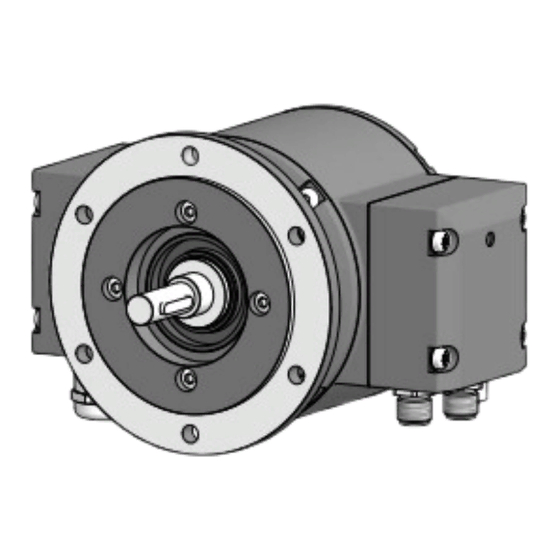
- Page 1 Installation and operating instructions PMG 10 - Profibus DP Absolute Encoder with magnetic sensing...
-
Page 2: Table Of Contents
4.2.1 Mounting the spring disk coupling to the encoder ������������������������������������������������9 4.2.2 Mounting to drive shaft �����������������������������������������������������������������������������������������9 4.2.3 Mounting the housing foot and the spring disk coupling to drive shaft ���������������10 4.3 Maximum permissible mounting tolerances when the Baumer Hübner K 35 spring disk coupling is used ������������������������������������������������������������������������������������������������������������... - Page 3 TABLE OF CONTENTS 5.1.3 Bus connecting box Profibus DP [ A ] - Version with connectors �������������������������15 5.1.3.1 Connector M12 [C] „Voltage supply“ (male, 4-pin, A-coded) ���������������15 5.1.3.2 Connector M12 [D] „Data transmission“ (male, 5-pin, B-coded) ����������15 5.1.3.3 Connector M12 [E] „Data transmission“ (female, 5-pin, B-coded) �������15 5.1.4 View in bus connecting box Profibus DP [A] ������������������������������������������������������16 5.1.5 Setting for the terminating resistors ��������������������������������������������������������������������16 5.1.6 Setting for the user address �������������������������������������������������������������������������������16...
-
Page 4: Importent Notes
IMPORTENT NOTES IMPORTENT NOTES Symbol guide Warning Disregarding could result in serious injury, death or damage to property Attention Disregarding could result in damage to property or damage/malfunction of the en- coder Information Additional information and recommendations Intended use The encoder is a precision measurement device for the acquisition of speed/position in- formation for the control of drive units and the provision of electronic output signals for downstream devices. -
Page 5: Maintenance And Lifetime
IMPORTENT NOTES Maintenance and lifetime The encoder may be only opened as described in this instruction. Repair or maintenance work that requires opening the encoder completely must be carried out by the manufactu- rer� Alterations of the device are not permitted. The expected operating life of the device depends on the ball bearings, which are equipped with a permanent lubrication. -
Page 6: Safety And Attention Instructions
SAFETy AND ATTENTION INSTRUCTIONS SAFETY AND ATTENTION INSTRUCTIONS Safety instructions Explosion risk Spark formation can cause a fire or an explosion. » Do not use the encoder in areas with explosive and/or highly infl ammable materi- als. They may explode and/or catch fire by possible spark formation. Risk of serious injuries due to rotating shafts Hair and clothes may become tangled in rotating shafts. -
Page 7: Attention Instructions For Mounting And Operation
SAFETy AND ATTENTION INSTRUCTIONS Attention instructions for mounting and operation Risk of destruction due to electrostatic charge Electronic parts contained in the encoder are sensitive to high voltages. » Do not touch plug contacts or electronic components. » Protect output terminals against external voltages. »... -
Page 8: Preparation
PREPARATION PREPARATION Scope of delivery Version with EURO flange B10* [ B ] [ A ] Version with housing foot B3* [ C ] [ A ] Housing Radial terminal boxes (see section [ A ] Bus connecting box Profibus DP EURO flange B10* [ B ] Speed switch* + additional output Solid shaft with key... -
Page 9: Required Accessory For Mounting (Not Included In Scope Of Delivery)
PREPARATION Required accessory for mounting (not included in scope of delivery) Connecting cables and connectors are required for the electrical connection. Details section 5, page 13� Spring disk coupling K 35, available as accessory, see section 4.3, page 11� For mounting with EURO flange B10 Installation fitting, customized Fixing screw for installation fitting ISO 4017, M6x16 mm... -
Page 10: Mounting
Mounting with EURO flange B10 4.1.1 Mounting the spring disk coupling to the encoder We recommend using the Baumer Hübner spring disk coupling K 35, see section 4.3, page 11, available as accessory. When other couplings are used pay attention to manufacturer‘s notes. -
Page 11: Mounting The Spring Disk Coupling To Drive Shaft
MOUNTING / MOUNTING WITH EURO FLANGE B10 4.1.3 Mounting the spring disk coupling to drive shaft 2�5 mm = 2-3 Nm 8/29 MB247EN - 11171697, 17A2, Baumer_PMG10-ProfibusDP_II_EN... -
Page 12: Mounting With Housing Foot B3
Mounting with housing foot B3 4.2.1 Mounting the spring disk coupling to the encoder We recommend using the Baumer Hübner spring disk coupling K 35, see section 4.3, page 11, available as accessory. When other couplings are used pay attention to manufacturer‘s notes. -
Page 13: Mounting The Housing Foot And The Spring Disk Coupling To Drive Shaft
MOUNTING / MOUNTING WITH HOUSING FOOT B3 4.2.3 Mounting the housing foot and the spring disk coupling to drive shaft 10 mm 2�5 mm = 2-3 Nm 90 mm 10/29 MB247EN - 11171697, 17A2, Baumer_PMG10-ProfibusDP_II_EN... -
Page 14: Maximum Permissible Mounting Tolerances When The Baumer Hübner K 35 Spring Disk Coupling Is Used
Maximum permissible mounting tolerances when the Baumer Hübner K 35 spring disk coupling is used Encoders should be driven through the Baumer Hübner K 35 spring disk coupling (acces- sory), that can be pushed onto the shaft without axial loading. -
Page 15: Note When Using A Jaw-Type Coupling (For Example „Rotex®")
MOUNTING Note when using a jaw-type coupling (for example „ROTEX®“) Incorrect mounting of the jaw-type coupling can damage the encoder. Avoid blocking of both coupling halves (claws pressed together). The encoder shaft must not subjected to direct axial shock. » Use a depth gauge to find and observe the correct distances (L, L1) for the versi- on with EURO flange B10, see below. -
Page 16: Electrical Connection
ELECTRICAL CONNECTION / PROFIBUS DP ELECTRICAL CONNECTION Profibus DP Please find a detailed instruction for the Profibus DP interface and the device de- scription file in the manual on the CD provided with the device. 5.1.1 Features Bus protocol Profibus DP V0* or Profibus DP V2* Profibus-Features Profibus DP V0 = Device Class 1 and 2 Profibus DP V2 = Device Class 3 and 4... -
Page 17: Cable Connection For Version With Cable Glands
ELECTRICAL CONNECTION / PROFIBUS DP 5.1.2 Cable connection for version with cable glands To ensure the specified protection of the device the correct cable diameter must be used. Connecting cables are not in scope of delivery. Bus connecting box Profibus DP TX 20 Torx and slotted screw, M4x32 mm... -
Page 18: Bus Connecting Box Profibus Dp [ A ] - Version With Connectors
ELECTRICAL CONNECTION / PROFIBUS DP Bus connecting box Profibus DP [ A ] - Version with connectors 5.1.3 Bus connecting box Profibus DP [ A ] [ D ] [ E ] [ C ] 5.1.3.1 Connector M12 [C] „Voltage supply“ (male, 4-pin, A-coded) MALE CONNECTION DESCRIPTION Voltage supply 10...30 VDC... -
Page 19: View In Bus Connecting Box Profibus Dp
ELECTRICAL CONNECTION / PROFIBUS DP 5.1.4 View in bus connecting box Profibus DP [A] Setting for the terminating resistors Setting for the user address Terminal assignment Negative serial data transmission, pair 1 and pair 2 Positive serial data transmission, pair 1 and pair 2 Voltage supply 10...30 VDC Ground for UB Terminals of the same significance are internally connected and identical in their... -
Page 20: Speed Switch And Additional Output Incremental
ELECTRICAL CONNECTION / SPEED SWITCH AND ADDITIONAL OUTPUT INCREMENTAL Speed switch and additional output incremental (Depending on version) 5.2.1 Terminal significance Voltage supply Ground Channel A+ Channel A _ (Channel A+ inverted) Channel B+ Channel B _ (Channel B+ inverted) Zero pulse (reference signal) Zero pulse inverted System OK+ / error output... -
Page 21: Led Function Displays
ELECTRICAL CONNECTION / SPEED SWITCH AND ADDITIONAL OUTPUT INCREMENTAL 5.2.3 LED function displays green INC1 Without function Without function INC2 Undervoltage (additional output Overload incremental) Over-temperature Status Internal error Speed Speed higher switching speed Speed lower switching speed (overspeed) 5.2.4 Speed switch - Switching characteristics Event State of the speed switch output... -
Page 22: Cable Connection
ELECTRICAL CONNECTION / SPEED SWITCH AND ADDITIONAL OUTPUT INCREMENTAL 5.2.5 Cable connection To ensure the specified protection of the device the correct cable diameter must be used. Connecting cables are not in scope of delivery. Mt = 2-3 Nm TX 20 Terminal box cover Torx and slotted screw, M4x32 mm... -
Page 23: Assignment Connecting Terminal
ELECTRICAL CONNECTION / SPEED SWITCH AND ADDITIONAL OUTPUT INCREMENTAL 5.2.6 Assignment connecting terminal Do not connect voltage supply to outputs! Danger of damage! Please, beware of possible voltage drop in long cable leads (inputs and out- puts)! 5.2.6.1 Connecting terminal terminal box [B] Speed switch/additonal output SP+* SP-*... -
Page 24: Dimensions
DIMENSIONS / VERSION WITH EURO FLANGE B10 DIMENSIONS Version with EURO flange B10 Speed switch Profibus DP [ A ] Additional output [ C ] [ B ] Positive rotating direction [ C ] [ D ] [ E ] All dimensions in millimeters, unless otherwise stated. -
Page 25: Version With Housing Foot B3
DIMENSIONS / VERSION WITH HOUSING FOOT B3 Version with housing foot B3 Speed switch Profibus DP [ A ] Additional output Positive rotating direction [ C ] [ B ] [ C ] [ D ] [ E ] All dimensions in millimeters, unless otherwise stated. 22/29 MB247EN - 11171697, 17A2, Baumer_PMG10-ProfibusDP_II_EN... -
Page 26: Dismounting
DISMOUNTING / VERSION WITH EURO FLANGE B10 DISMOUNTING Version with EURO flange B10 2�5 mm 10 mm 2�5 mm 23/29 MB247EN - 11171697, 17A2, Baumer_PMG10-ProfibusDP_II_EN... -
Page 27: Version With Housing Foot B3
DISMOUNTING / VERSION WITH HOUSING FOOT B3 Version with housing foot B3 10 mm 2�5 mm 2�5 mm 24/29 MB247EN - 11171697, 17A2, Baumer_PMG10-ProfibusDP_II_EN... -
Page 28: Technical Data
TECHNICAL DATA TECHNICAL DATA Technical data - electrical ratings Voltage supply 10...30 VDC Short-circuit proof Consumption w/o load ≤200 mA Initializing time ≤500 ms after power on Interface Profibus DP Function Multiturn Transmission rate 9.6...12000 kBaud Device adress Rotary switches in bus connecting box (type-specific) Steps per turn 8192 / 13 bit... -
Page 29: Technical Data - Mechanical Design
TECHNICAL DATA Technical data - mechanical design Size (flange) ø115 mm Shaft type ø11 mm solid shaft Flange EURO flange B10 Protection DIN EN 60529 IP 66/IP 67 Operating speed ≤6000 rpm Range of switching speed ±2...6000 rpm, default 6000 rpm Operating torque typ. - Page 30 MB247EN - 11171697, 17A2, Baumer_PMG10-ProfibusDP_II_EN...
- Page 31 MB247EN - 11171697, 17A2, Baumer_PMG10-ProfibusDP_II_EN...
- Page 32 Baumer Hübner GmbH P.O. Box 12 69 43 · 10609 Berlin, Germany Phone: +49 (0)30/69003-0 · Fax: +49 (0)30/69003-104 info@baumerhuebner.com · www.baumer.com/motion MB247EN - 11171697, 17A2 (03.08.2017), Baumer_PMG10-ProfibusDP_II_EN...
Need help?
Do you have a question about the PMG 10 Profibus DP and is the answer not in the manual?
Questions and answers