
Subscribe to Our Youtube Channel
Related Manuals for IBM DPI C13 PDU+

Summary of Contents for IBM DPI C13 PDU+
- Page 1 DPI C13 PDU+, DPI C19 PDU+, and DPI C19 3-phase PDU+ Installation and Maintenance Guide...
- Page 3 DPI C13 PDU+, DPI C19 PDU+, and DPI C19 3-phase PDU+ Installation and Maintenance Guide...
- Page 4 Note: Before using this information and the product it supports, read the warranty information in Appendix B, “IBM Statement of Limited Warranty Z125-4753-08 04/2004,” on page 49 and the notices information in Appendix C, “Notices,” on page 67. First Edition (May 2006) ©...
-
Page 5: Table Of Contents
Chapter 1. Introduction ..... . 1 The IBM Documentation CD ....1 Hardware and software requirements . - Page 6 Appendix B. IBM Statement of Limited Warranty Z125-4753-08 04/2004 Part 1 - General Terms ..... . 49 Part 2 - Country-unique Terms ....52 Part 3 - Warranty Information .
-
Page 7: Safety
Vor der Installation dieses Produkts die Sicherheitshinweise lesen. Prima di installare questo prodotto, leggere le Informazioni sulla Sicurezza. Les sikkerhetsinformasjonen (Safety Information) før du installerer dette produktet. Antes de instalar este produto, leia as Informações sobre Segurança. © Copyright IBM Corp. 2006... - Page 8 All caution and danger statements in this documentation end with a number. This number is used to cross reference an English caution or danger statement with translated versions of the caution or danger statement in the IBM ERserver Safety Notices document.
- Page 9 DANGER Electrical voltage and current from power, telephone, and communication cables are hazardous. To avoid a shock hazard: v Do not connect or disconnect any cables or perform installation, maintenance, or reconfiguration of this product during an electrical storm. v Connect all power cords to a properly wired and grounded electrical outlet.
- Page 10 The following general safety information should be used for all rack-mounted devices: DANGER v Always lower the leveling pads on the rack cabinet. v Always install stabilizer brackets on the rack cabinet. v To avoid hazardous conditions due to uneven mechanical loading, always install the heaviest devices in the bottom of the rack cabinet.
- Page 11 CAUTION: To prevent damage to a power device and other connected devices, always connect the power device to an authorized power source for that device. CUIDADO: Para evitar danos ao dispositivo de alimentação e outros dispositivos conectados, conecte sempre o dispositivo de alimentação a uma fonte de alimentação autorizada para este dispositivo.
- Page 12 ATTENZIONE: Per evitare danni all’alimentatore e agli altri dispositivi collegati, collegare sempre l’alimentatore ad una sorgente di alimentazione adatta a questo dispositivo. PRECAUIÓN: Conecte siempre el dispositivo a una fuente de alimentación aprobada para dicho dispositivo con el fin de evitar posibles daños al dispositivo o a otros aparatos eléctricos que tenga conectados.
-
Page 13: Chapter 1. Introduction
PDU documentation. These updates are available from the IBM Web site. To check for updated documentation and technical updates, complete the following steps. -
Page 14: Notices And Statements In This Document
Notices and statements in this document The caution and danger statements that appear in this document are also in the multilingual Safety Information document, which is on the IBM Documentation CD. Each statement is numbered for reference to the corresponding statement in the Safety Information document. -
Page 15: Installation Requirements
Installation requirements You will need the following tools to install the PDU in a rack cabinet: v One Phillips screwdriver v One 10 mm (11/32-in.) wrench v One cage-nut-insertion tool or flat-blade screwdriver (for installing cage nuts in some rack cabinets) You can install a PDU vertically in the side of a rack cabinet or horizontally within 1 of EIA mounting space in a rack cabinet. -
Page 16: Features Of The Pdu
Two vertical-mounting brackets (for IBM Enterprise rack cabinets only) v One cable-management bracket (for vertical installations) v One DB9-to-RJ-45 cable v One 1-U blank filler panel v Miscellaneous hardware kit (for attaching the mounting brackets to the PDU and... -
Page 17: Hardware Components
The following illustration shows the components and controls on the front of the DPI C19 PDU+ and the DPI C19 3-Phase PDU+. Note: The IBM DPI C19 3-Phase PDU+ comes with an attached power cord. RS-232 serial connector... - Page 18 Operation mode DIP switch Sets the mode of operation for the PDU. The default mode is S1 off, S2 off for normal operation. 1=Off, 2=Off The card will run normal operational firmware. 1=On, 2=On The card will start in diagnostics mode. 1=On, 2=Off Serial upgrade mode.
-
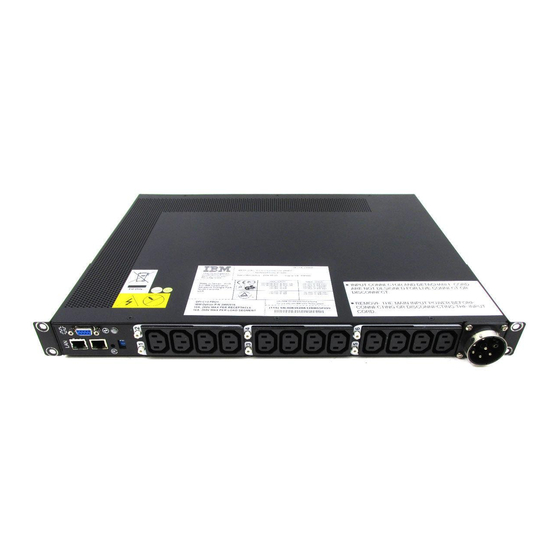
Page 19: Rear View
Rear view The following illustration shows the rear of the DPI C13 PDU+. The following illustration shows the power outlets on the rear of the DPI C19 PDU+ and the DPI C19 3-Phase PDU+. Labels indicating associated outlets breakers on the front of the PDU PDU load groups The PDU load groups are described in the following tables. - Page 20 DPI C13 PDU+, DPI C19 PDU+, and DPI C19 3-phase PDU+: Installation and Maintenance Guide...
-
Page 21: Chapter 2. Installing The Pdu Vertically In A Rack Cabinet
PDU with two M3x5 screws per bracket. Use the screws that come with the PDU. You can install the PDU in a rack cabinet with the power outlets facing the rear or the front of the rack cabinet. © Copyright IBM Corp. 2006... - Page 22 2. Hold the PDU in the side of the rack cabinet, and attach the vertical-mounting brackets to the side braces with four M6 screws and nuts that come with the PDU. Notes: a. Leave enough space to connect, route, and disconnect power cables. b.
- Page 23 4. Install the optional cable-management bracket beside the PDU with four M6 screws and nuts that come with the PDU. 5. Route the power cord from the PDU toward the rack cabinet side braces; then, route the power cord along a side brace toward the back of the rack cabinet and secure the power cord with the cable straps that come with the PDU.
-
Page 24: Installing The Pdu In The Side Of An Ibm Enterprise Rack Cabinet Only
Use cable straps as required. Installing the PDU in the side of an IBM Enterprise rack cabinet only Note: Removing the rack doors and side panels might make installation easier. - Page 25 You must use clip nuts to install the mounting brackets. Clip nuts come with the PDU and install on the rack mounting flanges, as shown in the following illustration. To install the PDU in the 1-U mounting space in the side of an IBM Enterprise rack cabinet, complete the following steps.
- Page 26 3. Align the PDU with the opening in the side of the rack cabinet; then, while holding the PDU in place, attach the brackets to the rack-mounting flanges with four clip nuts and four M6 screws that come with the PDU. Attention: You must disconnect the main input power before connecting or disconnecting the input power cord from the PDU.
- Page 27 5. Route the power cord from the PDU toward the rack cabinet side braces; then, route the power cord along a side brace toward the back of the rack cabinet and secure the power cord with the cable straps that come with the PDU. 6.
- Page 28 DPI C13 PDU+, DPI C19 PDU+, and DPI C19 3-phase PDU+: Installation and Maintenance Guide...
-
Page 29: Chapter 3. Cabling The Pdu
Serial connector For more information, see “Using the IBM DPI Configuration Utility” on page 19. Connecting to a LAN You can monitor the PDU power outlets and digital outputs over a network through the Web interface using a LAN connection. -
Page 30: Connecting Output Devices
Connecting output devices The PDU has nine or 12 power outlets for connecting devices such as workstations, servers, and printers. You can monitor the power status of a connected device either manually or remotely through the LAN and console connectors. Connect a device that you want to monitor to a power outlet on the PDU with the power cord that comes with the device. -
Page 31: Chapter 4. Monitoring The Power Status
You can monitor the power status for any device that is connected to the PDU, either manually or remotely, through the PDU Web interface. You can use the IBM DPI Configuration Utility to initially set up the PDU and to configure PDU settings such as network parameters, access control table, and trap receivers table. - Page 32 To start HyperTerminal and communicate with the PDU, complete the following steps: 1. To start HyperTerminal, click Start → Programs → Accessories → Communications → HyperTerminal. The Connection Description window opens. 2. Type the name for the connection in the Name field and select an icon for the connection.
- Page 33 3. In the Connect using field, select the COM port that is connected to the PDU. Click OK. The Properties window opens. 4. Click Restore Defaults to use the default settings. Make sure that the Bits per second field is 9600 and that the Flow control field is None. Click OK. Chapter 4.
- Page 34 5. Press any key. The IBM DPI Configuration Utility main menu opens and you are prompted for a password. Type the default password (passw0rd) and press Enter. The IBM DPI Configuration Utility main window opens. See “Configuration Utility menu choices” on page 23 for descriptions of the choices on this window.
-
Page 35: Configuration Utility Menu Choices
The following choices are on the Configuration Utility main menu: v IBM DPI Settings When you select IBM DPI Settings, the following window opens. The following choices are available: – Set the IP Address, Gateway Address and MIB System Group Select this choice to view and change the IP address, date, time, and MIB system information. -
Page 36: Setting The Ip Address
To set the IP address of the PDU, in the Configuration Utility main menu, select IBM DPI Settings and then select Set the IP Address, Gateway Address and MIB System Group. You must set the IP address before you can access the PDU in an IP network (LAN/WAN). -
Page 37: Using The Web Interface
Using the Web interface This section provides information about using the Web interface to configure and monitor the PDU remotely. The PDU provides a graphical user interface that you can view from a Web browser. Using a Web browser, you can access and monitor the PDU power outlets and output devices remotely from a workstation or notebook computer. -
Page 38: Environment Status And Configuration
Environment status and configuration If an environmental monitoring probe is connected to the PDU, you can view the temperature and humidity information. For more information about installing and using the environmental monitored probe, see Chapter 5, “Using the environmental monitoring probe,” on page 37. Viewing the status You can view the environment status (temperature and humidity) on the Status of Environment Sensor page. - Page 39 Changing the configuration settings You can change the system configuration of the environment sensor on the Configuration of Environment Sensor page. To configure the environmental monitored probe that is connected to the PDU, click Configuration under Environment. You can set the sensor names, high and low set points, and the calibration offsets for the sensors.
-
Page 40: Modifying The Basic Settings
Modifying the basic settings Use the System menu to configure the PDU system parameters such as the superuser name, password, IP address, date, time, and so on. Some of these settings are described in the following sections. Changing the superuser name and password You can set the user name and password of the administrator who will use a Web browser to configure the PDU on the Configuration page. - Page 41 Identifying the PDU and Web/SNMP card You can view the PDU and Web/SNMP card information on the Identification of Power Management page. To view the power management information of the PDU and Web/SNMP card, complete the following steps: 1. From the main status page, in the left navigation pane, click System. 2.
- Page 42 Adding users You can add users who can access and control the PDU on the Multi-User Configuration page. To create a list of users who can access and control the PDU, complete the following steps: 1. From the main status page, in the left navigation pane, click System. 2.
- Page 43 Changing the date and time You can change the date and time of the PDU on the Date and Time page. Note: Changing the PDU date and time affects other system settings such as e-mail, traps, and logs. To change the date and time, complete the following steps: 1.
- Page 44 Changing event alerts You can change event alerts on the SNMP Trap Receivers page. To configure the PDU to send e-mail or SNMP trap alerts to specified users when specific events occur, complete the following steps: 1. From the main status page, in the left navigation pane, click System. 2.
- Page 45 3. Click Email Notification under System to create a list of up to four users who will be alerted with an e-mail. Use this menu to specify the mail server, user account, DNS, and other information necessary to set up a mail server for sending mail alerts.
-
Page 46: Changing The Network Information
Changing the network information Use the Network menu to change the network information for the PDU, for example, the IP address. Changing the network configuration To view or change the network configuration of the PDU, under Network, click Configuration. You can set the PDU IP address, gateway address, subnet mask, and Domain Name System (DNS) address. -
Page 47: History And Event Log Summaries
History and event log summaries The Logs menu provides a detailed description of all events and a record of the PDU status. System administrators can use this page to analyze problems with network equipment. Viewing the history log You can view the complete history of the PDU inputs, outputs, and environmental monitored probe on the History Log page. - Page 48 DPI C13 PDU+, DPI C19 PDU+, and DPI C19 3-phase PDU+: Installation and Maintenance Guide...
-
Page 49: Chapter 5. Using The Environmental Monitoring Probe
Web browser, providing greater power management control and flexible monitoring. You can use the environmental monitoring probe with any IBM DPI PDU+ models. When the environmental monitoring probe is connected to the RJ-45 console connector on the PDU, temperature and humidity readings are automatically displayed in the Web interface. -
Page 50: Installing The Environmental Monitoring Probe
Installing the environmental monitoring probe To install the environmental monitoring probe, complete the following steps: 1. If applicable, connect external contact closure inputs to the screw terminals on the environmental monitoring probe. Pin 1 Environmental monitoring probe screw terminals Note: Contact closure device 1 is connected between pins 1 and 2. Device 2 is connected between pins 3 and 4 (as labeled to show device 1 and 2). - Page 51 4. Start a Web browser and connect to the PDU IP address (for more information, see “Using the Web interface” on page 25). The Web interface main status page opens. Click Environment, then click Status. The Status of Environment Sensor page opens. The temperature and humidity status is automatically displayed.
- Page 52 You can configure and enable both contacts and set upper and lower ranges of temperature and humidity that will generate SNMP traps and e-mail notification if the PDU is configured to do so. DPI C13 PDU+, DPI C19 PDU+, and DPI C19 3-phase PDU+: Installation and Maintenance Guide...
-
Page 53: Chapter 6. Hardware Maintenance Information
Important: The PDU does not contain any serviceable parts. Customer replaceable unit part numbers IBM customer replaceable unit (CRU) part numbers are subject to change without notice. This section contains a listing of the PDU and power cord CRU part numbers that are available as of the date of this printing. - Page 54 DPI C13 PDU+, DPI C19 PDU+, and DPI C19 3-phase PDU+: Installation and Maintenance Guide...
-
Page 55: Chapter 7. Pdu Specifications
Operating temperature at 0-914 m 10°- 35°C (50°- 95°F) (0-3000 ft) (room ambient) Operating temperature at 914-2133 m 10°- 32°C (50°- 90°F) (3000-7000 ft) (room ambient) Operating humidity 8-80% (noncondensing) Localized air temperature in PDU 60°C (140°F) maximum © Copyright IBM Corp. 2006... - Page 56 Rated voltage 1. 220-240 V ac, 32 amps, single-phase 2. 200-208 V ac, 48 amps, single-phase 3. 220-240 V ac, 63 amps, single-phase 4. 220-240 V ac, 32 amps, three-phase Wye 5. 200-208 V ac, 24 amps, single-phase 6. 200-208 V ac, 48 amps, three-phase Delta 7.
- Page 57 You must connect the connector on the power cord that comes with your Enterprise PDU to a properly wired and grounded outlet. The following table shows illustrations of the power cord connector and the correct outlet for each of the Enterprise PDUs. Plug Outlet Rating...
- Page 58 DPI C13 PDU+, DPI C19 PDU+, and DPI C19 3-phase PDU+: Installation and Maintenance Guide...
-
Page 59: Appendix A. Getting Help And Technical Assistance
If you need help, service, or technical assistance or just want more information about IBM products, you will find a wide variety of sources available from IBM to assist you. This appendix contains information about where to go for additional information about IBM and IBM products, what to do if you experience a problem with your system or optional device, and whom to call for service, if it is necessary. -
Page 60: Getting Help And Information From The World Wide Web
Getting help and information from the World Wide Web On the World Wide Web, the IBM Web site has up-to-date information about IBM ® systems, optional devices, services, and support. The address for IBM xSeries ® BladeCenter information is http://www.ibm.com/eserver/xseries/. The address for IBM IntelliStation information is http://www.ibm.com/intellistation/. -
Page 61: Appendix B. Ibm Statement Of Limited Warranty Z125-4753-08 04/2004
Country-unique Terms, and Part 3 - Warranty Information. The terms of Part 2 replace or modify those of Part 1. The warranties provided by IBM in this Statement of Limited Warranty apply only to Machines you purchase for your use, and not for resale. - Page 62 If the Machine does not function as warranted during the warranty period, contact IBM or your reseller to obtain warranty service. If you do not register the Machine with IBM, you may be required to present proof of purchase as evidence of your entitlement to warranty service.
- Page 63 Personal Data. Limitation of Liability IBM is responsible for loss of, or damage to, your Machine only while it is 1) in IBM’s possession or 2) in transit in those cases where IBM is responsible for the transportation charges.
-
Page 64: Part 2 - Country-Unique Terms
TO YOU. Governing Law Both you and IBM consent to the application of the laws of the country in which you acquired the Machine to govern, interpret, and enforce all of your and IBM’s rights, duties, and obligations arising from, or relating in any manner to, the subject matter of this Statement of Limited Warranty, without regard to conflict of law principles. - Page 65 Limitation of Liability: The following is added at the end of this section: In accordance with Article 1328 of the Peruvian Civil Code the limitations and exclusions specified in this section will not apply to damages caused by IBM’s willful misconduct (“dolo”) or gross negligence (“culpa inexcusable”).
- Page 66 Limitation of Liability: The following is added to this section: Where IBM is in breach of a condition or warranty implied by the Trade Practices Act 1974 or other similar legislation, IBM’s liability is limited to the repair or replacement of the goods or the supply of equivalent goods.
- Page 67 2. as to any other actual damage arising in any situation involving nonperformance by IBM pursuant to, or in any way related to the subject of this Statement of Limited Warranty, the charge paid by you for the individual Machine that is the subject of the claim.
- Page 68 Consumer Guarantees Act 1993 or other legislation which cannot be excluded or limited. The Consumer Guarantees Act 1993 will not apply in respect of any goods which IBM provides, if you require the goods for the purposes of a business as defined in that Act.
- Page 69 Machine in any of those countries from either (1) an IBM reseller approved to perform warranty service or (2) from IBM, provided the Machine has been announced and made available by IBM in the country in which you wish to obtain service.
- Page 70 The phrase “the laws of the country in which you acquired the Machine” is replaced 1) “the laws of Austria” in Albania, Armenia, Azerbaijan, Belarus, Bosnia-Herzegovina, Bulgaria, Croatia, Georgia, Hungary, Kazakhstan, Kyrgyzstan, FYR Macedonia, Moldova, Poland, Romania, Russia, Slovakia, Slovenia, Tajikistan, Turkmenistan, Ukraine, Uzbekistan, and FR Yugoslavia; 2) “the laws of France”...
- Page 71 598 (2) of the Austrian Code of Civil Procedure, the parties expressly waive the application of paragraph 595 (1) figure 7 of the Code. IBM may, however, institute proceedings in a competent court in the country of installation.
- Page 72 Except as otherwise provided by mandatory law: 1. IBM’s liability for any damages and losses that may arise as a consequence of the fulfillment of its obligations under or in connection with this Statement of Limited Warranty or due to any other cause related to this Statement of Limited...
- Page 73 The limitation period for consumers in action for breach of warranty is the statutory period as a minimum. In case IBM or your reseller is unable to repair an IBM Machine, you can alternatively ask for a partial refund as far as justified by the reduced value of the unrepaired Machine or ask for a cancellation of the respective agreement for such Machine and get your money refunded.
- Page 74 For the purposes of this section, a “Default” means any act, statement, omission, or negligence on the part of IBM in connection with, or in relation to, the subject matter of this Statement of Limited Warranty in respect of which IBM is legally liable to...
- Page 75 For the purposes of this section, a “Default” means any act, statement, omission, or negligence on the part of IBM in connection with, or in relation to, the subject matter of this Statement of Limited Warranty in respect of which IBM is legally liable to you, whether in contract or tort.
-
Page 76: Part 3 - Warranty Information
Note: “Region” means either Hong Kong or Macau Special Administrative Region of China. A warranty period of 3 years on parts and 1 year on labor means that IBM provides warranty service without charge for: 1. parts and labor during the first year of the warranty period; and 2. - Page 77 IBM at any time on your request. Installation of Tier 1 CRUs is your responsibility. If IBM installs a Tier 1 CRU at your request, you will be charged for the installation. You may install a Tier 2 CRU yourself or request IBM to install it, at no additional charge, under the type of warranty service designated for your Machine.
- Page 78 When a 5, 6 or 7 type of warranty service is listed, IBM will determine which type of warranty service is appropriate for the repair. * This type of service is called ThinkPad EasyServ or EasyServ in some countries. The IBM Machine Warranty World Wide Web site at http://www.ibm.com/servers/ support/machine_warranties/ provides a worldwide overview of IBM’s Limited...
-
Page 79: Appendix C. Notices
Web sites. The materials at those Web sites are not part of the materials for this IBM product, and use of those Web sites is at your own risk. IBM may use or distribute any of the information you supply in any way it believes appropriate without incurring any obligation to you. -
Page 80: Trademarks
IBM makes no representations or warranties with respect to non-IBM products. Support (if any) for the non-IBM products is provided by the third party, not IBM. Some software may differ from its retail version (if available), and may not include user manuals or all program functionality. -
Page 81: Product Recycling And Disposal
This unit must be recycled or discarded according to applicable local and national regulations. IBM encourages owners of information technology (IT) equipment to responsibly recycle their equipment when it is no longer needed. IBM offers a variety of product return programs and services in several countries to assist equipment owners in recycling their IT products. -
Page 82: Battery Return Program
United States, go to http://www.ibm.com/ibm/environment/ products/batteryrecycle.shtml or contact your local waste disposal facility. In the United States, IBM has established a return process for reuse, recycling, or proper disposal of used IBM sealed lead acid, nickel cadmium, nickel metal hydride, and battery packs from IBM equipment. -
Page 83: Industry Canada Class A Emission Compliance Statement
IBM cannot accept responsibility for any failure to satisfy the protection requirements resulting from a nonrecommended modification of the product, including the fitting of non-IBM option cards. This product has been tested and found to comply with the limits for Class A Information Technology Equipment according to CISPR 22/European Standard EN 55022. -
Page 84: Taiwanese Class A Warning Statement
Taiwanese Class A warning statement Chinese Class A warning statement Japanese Voluntary Control Council for Interference (VCCI) statement DPI C13 PDU+, DPI C19 PDU+, and DPI C19 3-phase PDU+: Installation and Maintenance Guide... -
Page 85: Index
(vertical rack-mounting) 12 installation requirements 3 setting PDU IP address LED, green 5 using Configuration Utility 24 load groups, PDU 7 using Web interface 34 specifications, PDU 43 statements and notices 2 monitoring power status 19 © Copyright IBM Corp. 2006... - Page 86 terminal program, using to configure PDU 20 trademarks 68 United States electronic emission Class A notice 70 United States FCC Class A notice 70 Web interface Environment page changing configuration 27 viewing status 26 History page viewing history log 35 Network page changing network configuration 34 starting 25...
- Page 88 Part Number: 40K9635 Printed in USA (1P) P/N: 40K9635...
Need help?
Do you have a question about the DPI C13 PDU+ and is the answer not in the manual?
Questions and answers