Table of Contents
Advertisement
Quick Links
last update: 20. 8. 2019
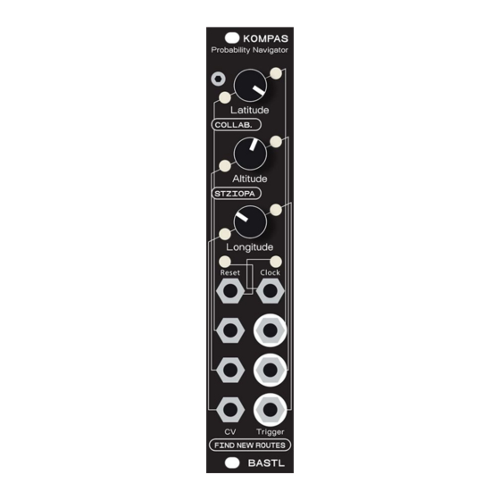
KOMPAS v1.2 - Assembly Guide
bastl-instruments.com
INTRODUCTION
This guide is for building K OMPAS module from Bastl Instruments. It is good to have basic soldering
skills and to be able to identify electronic components before starting this kit. However if you have
never soldered before, check out this
t utorial first
1
. We even included some of the best quality solder
to help you solder everything faster and better.
The KOMPAS kit consists of two boards. All the parts comes in three bags separated for Top board,
Bottom board and Assembly parts. See the Bill of Materials for detailed list.
1
https://cdn-learn.adafruit.com/downloads/pdf/adafruit-guide-excellent-soldering.pdf?timestamp=15596
28255
1
Advertisement
Table of Contents

Related Manuals for Bastl Instruments KOMPAS


Summary of Contents for Bastl Instruments KOMPAS
- Page 1 INTRODUCTION This guide is for building K OMPAS module from Bastl Instruments. It is good to have basic soldering skills and to be able to identify electronic components before starting this kit. However if you have never soldered before, check out this ...
-
Page 2: Bill Of Materials
BILL OF MATERIALS KOMPAS_V.1.2 BOM value part RESISTORS R-EU_0204/5 R-EU_0204/5 100k R-EU_0204/5 R-EU_0204/5 CAPACITORS 100nF ceramic capacitor 10uF electrolytic capacitor SEMICONDUCTORS 1N4007 DIODE-D-7.5 7805 voltage regulator NPN, B ULK 2N3904 MCP6004 IC - in foam ATMEGA328-PU IC - in foam... - Page 3 16mHz resonator 100mA fuse HARDWARE 14 pin DIL DIL socket - in foam 28 pin DIL DIL socket - in foam POT LIN B100k 20mm linear potentiometer PJ-301BMB jack 3.5mm 27 pin male 21 pin female 2x5 pin male 3 mm white ASSEMBLY M3_11,5_II spacer...
-
Page 4: Bottom Board
BOTTOM BOARD RESISTORS Start with the bottom board parts. First of all, take your time and check the v alues of all resistors using the multimeter (or you can check the color codes if you are seasoned enough): 1 k (7x), 1 0k (3x), ... - Page 5 MALE HEADERS Solder the m ale pinheaders now (one 6 pins and two d ouble 5 pins ) . Be careful to solder them straight. This part could be tricky: you may first solder just one of the pins , take the board in your hand and reheat that pin while pressing down on the header to align it (be careful, you don’t want to touch the pin that you are heating up).
-
Page 6: Ceramic Capacitors
CERAMIC CAPACITORS Let’s do the 1 00nF c eramic c apacitors n ow. There are t hree of them (marked “104” on itself). VOLTAGE REGULATOR Proceed to the 7 805 voltage regulator. Bend its legs close to the body first. Insert it then to the spot and make it lay on the PCB. - Page 7 TRANSISTORS Add t wo t ransistors ( 2 N3904 ) . Just be aware of the right o rientation . Also don’t try to push these parts on the board as you can see on the photo.
-
Page 8: Electrolytic Capacitors
ELECTROLYTIC CAPACITORS Let’s do the e lectrolytic c aps ( 2x 1 0μF ) . These ones a re polarized! T here is a plus (+) sign on the PCB that has to match the longer lead of the electrolytic capacitor (actually the minus (–) side is also marked on the body of the capacitor with a white strip). - Page 9 RESONATOR Insert also the r esonator (the orange component with 3 leads). This part is not polarized so you can insert it in any direction. INSERTING ICs Next don’t forget to place I Cs into the sockets (1x M CP6004 , 1x A tmega ) . T here is a notch on each IC that should match with the notch on the socket.
-
Page 10: Top Board
TOP BOARD RESISTORS Let's move to the top PCB now. Again, start with the r esistors : 1 k (8x), 1 M (3x). You are going to place them from both sides of the PCB. Just be sure that the legs are properly cut so they are not going to be touched with the jacks. - Page 11 PINHEADERS Now it’s time to connect the boards with pinheaders: 1) Mount the spacer (nut x nut) with the screw to the bottom board first. 2) Insert male headers into the female ones. 3) Put the headers on the bottom board facing the female ones down. 4) Place the top board on and secure it with the other spacer.
- Page 13 JACK CONNECTORS, POTENTIOMETERS & LEDS You are almost done. Let's do the rest of the components by just putting them in first ( n o soldering yet! It starts at point 7 ) : 1) Unmount the top board. Unmount the spacers. 2) Mount the spacer (nut x screw) to the ...
- Page 14 4) Insert the w hite LEDs - w atch out f or orientation ! (the longer lead has to go into the plus (+) hole signed on PCB). 5) Insert j ack c onnectors (8x). 6) Place the ...
- Page 15 7) Check the position of all the parts if they are flat on the board and at the right angle, push the LEDs to the faceplate and do the soldering - for LEDs solder just one leg of each first, align them then to the faceplate.
- Page 16 This is also a right time to check the boards if everything is placed and soldered properly.
-
Page 17: Final Assembly
Congratulations! You have made it through. Now just put the boards back together, put the f aceplate on (secured by the screw and nuts with washers) and your KOMPAS is ready to work! Oh and don’t forget to put the k nobs and j umpers on (the l ed0 , l ed1 , l ed2 positions; 4th jumper must be left unconnected for default operation - see picture).
Need help?
Do you have a question about the KOMPAS and is the answer not in the manual?
Questions and answers