Advertisement
Table of Contents
- 1 Table of Contents
- 2 Precautions
- 3 Names and Functions of Parts
- 4 Outer Dimensions
- 5 Wiring Diagram
- 6 Function
- 7 Technical Points
- 8 Precautions for Failure Diagnosis
- 9 Troubleshooting Procedure
- 10 Troubleshooting
- 11 Routine Inspection and Maintenance
- 12 Service Checklist
- 13 Precautions for Disassembly and Reassembly
- 14 Disassembly and Reassembly Hints
- 15 Parts Catalog
- Download this manual
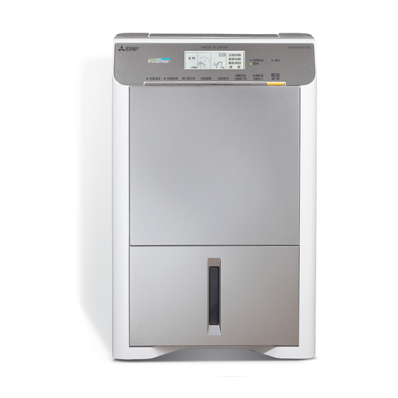
DEHUMIDIFIER
SERVICE MANUAL
MJ-EV210FJ-TW
Model
CONTENTS
1. Precautions ............................................................................................2
2. Names and Functions of Parts ...............................................................4
4. Outer Dimensions ...................................................................................6
5. Wiring Diagram .......................................................................................7
6. Function ..................................................................................................8
7. Technical Points .....................................................................................9
8. Precautions for Failure Diagnosis ........................................................11
9. Troubleshooting Procedure ..................................................................12
10. Troubleshooting ....................................................................................20
11. Routine Inspection and Maintenance ...................................................21
12. Service Checklist ..................................................................................22
13. Precautions for Disassembly and Reassembly ....................................23
14. Disassembly and Reassembly Hints ....................................................25
15. Parts Catalog ........................................................................................32
.........................................................................................6
2014
No.MJW-E-1405A
Sold from 2014
Advertisement
Table of Contents
Troubleshooting

Related Manuals for Mitsubishi Electric MJ-EV210FJ-TW


Summary of Contents for Mitsubishi Electric MJ-EV210FJ-TW
-
Page 1: Table Of Contents
2014 DEHUMIDIFIER SERVICE MANUAL No.MJW-E-1405A MJ-EV210FJ-TW Model Sold from 2014 CONTENTS 1. Precautions ....................2 2. Names and Functions of Parts ...............4 ..................6 4. Outer Dimensions ...................6 5. Wiring Diagram ..................7 6. Function ....................8 7. Technical Points ..................9 8. Precautions for Failure Diagnosis ............11 9. -
Page 2: Precautions
1. Precautions Note) This page is extracted from the instruction manual. 安全上請務必遵守之事項 注意 使用錯誤時可能導致之危險及其程度,以下列各 本文中所使用各標誌意義如下。 排水管四周如果在 0℃以下,則無 出風口或背面吸入口請勿以布、 警告標誌區分說明 (標示於機體上) 毯子類鋪蓋 法連續排水 禁止 禁止 遵照指示 警告 注意 分解 水管內部會因為結冰,而導致除濕水 禁止 禁止使用 通風不良會導致火災、發熱。 會漏出而浸濕傢俱等。 因操作錯誤,而可能造成 使用方法錯誤時可能導致 禁止 禁止 注意內有 拔掉插頭 死亡或重傷。 傷害或房屋傢俱等損害。... - Page 3 Note) This page is extracted from the instruction manual. 安全上請務必遵守之事項(續) 除濕時應注意的事項 注意 將儲水箱的水倒掉之後,握好 除濕前先把儲水箱的水倒乾淨 把手利用滑動輪移動 握住手把 除濕運轉時請把門及窗戶關閉 若傾倒等會造成地板的損害。 連續排水時,請注意排水管是 想乾燥衣物時 否彎折或高度落差等,確保能 使排水通暢 用脫水機脫乾水分後,皺紋拉平後再晾。將自動 把水倒乾淨 出風的擺葉,對準要晾的衣物。衣物最好保持距 除濕機的水漏出可能浸濕傢俱等。 離,以確保良好通風。 收藏後,若再重新使用或連續排水及 長時間使用時,請至少二週檢查一次 閉 在 門 狹 窗 小 排水管內若阻塞異物或污垢易 除 的 造成過熱或漏水。 濕 檢查...
-
Page 4: Names And Functions Of Parts
2. Names and Functions of Parts Note) This page is extracted from the instruction manual. 各部名稱與功能 正面 擺葉 出風口 操作面板 P10·22 倒水口上蓋 P10·22 水箱上蓋 浮筒 儲水箱 P10·22 購買時,若有發現儲水箱中有殘留的水,這是 水位視窗 感應器 工廠內進行除濕測試時所留下的,並非異常。 請勿遮蓋 背面 把手 背面吸氣口 P10·24~25 銀離子濾網 P10·24 前置濾網 由藍色的除菌濾網和白色的集塵濾網所構成的雙 重過濾網,請勿分解〈除菌性能試驗機關〉... - Page 5 Note) This page is extracted from the instruction manual. 本體 操作部 液晶顯示 操作部 ● 滿水指示燈 儲水箱滿指示燈會亮 以選擇 8 種運轉行程 標準 夜間乾衣 ● 關 / 開定時 ● 電源關 / 開 ● 空氣清淨指示燈 ● 內部乾燥指示燈 ● 濕度設定 ● 運轉模式指示燈 強 所有機種均有 運轉停止 / 啟動開關 在單一空氣清淨化...
-
Page 6: Outer Dimensions
Note) This page is extracted from the instruction manual. 規格 MJ-EV210FJ-TW 型 號 單相 110 V 60 Hz 電 源 21.0 L 除 濕 能 力 日 440 W 消 耗 電 力 13 ∼ 26 坪 標... -
Page 7: Wiring Diagram
5. Wiring Diagram 1) Wiring Diagram Operation and display boards CN709 CN704 CN703 CN101 CN702 Cooling fan Filter board Power supply board Stepping motor CN602 Tube temperature sensor CN705 CN706 CN503 Tank full switch Room temperature Board fin thermistor (Float) and humidity sensor Reactor 2) Board Diagram... -
Page 8: Function
6. Function 1) Function List Operating mode Compressor — — — — — — Blower fan — — — — — — Swing louvre CLOSE CLOSE CLOSE — ward Inverter indicator — INTELLIGENT LAUNDRY — NIGHT LAUNDRY — AIR PURIFIER —... -
Page 9: Technical Points
7. Technical Points Refrigerant circuit Compressor temperature thermistor Compressor Flow of refrigerant Dehumidification Defrosting Tube temperature sensor Outlet Inlet Humidity sensor Room temperature sensor Capillary tube... - Page 10 Performance curve Note) This page is extracted from the instruction manual. 除濕機的特徵 ● 運轉中,有時溫度會上升 ● 變頻器 2~6℃。 變頻器是控制壓縮機馬達轉速的裝置。在操作開始後或其 他情況時,會立即以高馬達轉速執行強除濕。並在濕度穩 除濕機沒有冷房能力。而且運轉中時會發熱,所以室 定下來時降低馬達轉速來維持較節能運轉。 溫有時會上升 2~6℃。 除濕機會吹出熱風是正常現象,並非故障。 (冬天溫度低時,有時所吹出的風會比體溫還低,所 ● 可運轉的室溫為 5 ∼ 40℃。 以不覺得風是暖的) 但,若室溫超過約 35℃時,會變成送風運轉或風量增強。 除濕原理 因本體內部的溫度會升高,為保護裝置產生作用之故。只 要停止擺葉的擺動、垂直使用擺葉,即可讓本體內部降溫。 將冰水倒入杯中,會令杯子周圍的空氣變冷,杯子 若室溫低於 5℃時,為防止已除濕的水結凍,會變成送 表面因而產生水滴。 風運轉。...
-
Page 11: Precautions For Failure Diagnosis
8. Precautions for Failure Diagnosis The following precautions should be observed in order to perform troubleshooting safely and correctly. The following categories describe hazards caused by mishandling and their levels. WARNING Mishandling may result in injuries or damage to your home or property, etc. CAUTION Meanings of graphic symbols are explained below. -
Page 12: Troubleshooting Procedure
9. Troubleshooting Procedure Perform the recommended actions Is an error displayed in the humidity display described in “Error Indications and section? Corrective Actions” When the POWER switch is turned ON, does Check the power cord conduction Replace the power cord the inverter lamp turn on? Check the insertion and connector Firmly insert the... - Page 13 Is the temperature of the Increase the temperature Does the compressor operate? operating environment low? in the operating (3°C or less) environment and then check. (Perform operation in HIGH mode) Check the insertion and Firmly insert the connector pins of connector connectors or connector CN101 of the power supply board pins in the trouble spots...
- Page 14 Is the tube temperature Check the power supply Firmly insert the thermistor normal? board CN707 connector connectors or insertion and connector pins connector pins Check the resistance values Replace the tube of the tube temperature temperature thermistor thermistor between terminals Abnormal: Open or shorted Replace the power supply board...
- Page 15 The louvre does not Does the swing louvre Is the swing louvre OFF? Normal swing change to Wide, Upward, and Rear? Check the insertion and Firmly insert the connector pins of the connectors or connector power supply board CN708 pins in the trouble spots connector and the stepping motor connector Check the resistance values...
- Page 16 2) Simple Check Table for Main Parts Part name Test criteria Disconnect the connector and measure the resistance value with a tester. (Part temperature 10°C to 30°C) Tube temperature sensor Normal Abnormal Open or shorted Disconnect the connector and measure the resistance value with a tester. (Part temperature Room temperature 10 °C to 30 °C) sensor...
- Page 17 3) Error Indications and Corrective Actions Indication (Timer time display Error (failure) Corrective action section) RAM error Replace the operation and display boards Frequency determination error Replace the power supply board Watchdog error (main stop) Replace the operation and display boards Watchdog error (interrupt stop) Bus undervoltage error Check the power supply...
- Page 18 4) Self Diagnosis Test Program (1) Deactivate 3-minute restart prevention Start ..Press the MODE and HUMIDITY SELECTION switches together 3 times when the power is off. Press the POWER switch within 2 seconds. Operations .
- Page 19 (3) Lamp, LCD test, and monitor display Start ..Press the MODE and HUMIDITY SELECTION switches together 4 times when the power is off. Press the POWER switch within 2 seconds. Mode selection ..Use the OFF/ON TIMER switch to change the diagnosis mode. Mode 0: All lamps and LCDs light Mode 1: Year/MAIN microprocessor version Mode 2: EEPROM model/EEPROM version...
-
Page 20: Troubleshooting
10. Troubleshooting Note) This page is extracted from the instruction manual. 懷疑是否故障時? 以下情況應並非故障。 狀況 原因 • 處理方法 狀況 原因 • 處理方法 是否放置不當而致機體傾倒搖晃。 除濕後的空氣,會經過加熱器後再以暖和的風吹出。(無冷氣機效 吹出熱風 請在安全平穩的地方使用。 果)這並非故障。 運轉聲音大 前置濾網是否阻塞。 有共振聲音 請依照「保養」所指示之方式清理乾淨。 溫度和濕度是否過低。 儲水箱中無水 在木板或狹小房間運轉時容易有共振聲音。 請先確認目前濕度。若濕度過低,會降低除濕能力。(因冬季乾燥 除濕量很少 可在機體下方鋪上軟墊,可減少共振聲音。 而使濕度降低,儲水箱中不易積存水。)這並非故障。 壓縮機剛啟動時聲音會比較大。(電源開啟約 3 分鐘後或在節能自 使... -
Page 21: Routine Inspection And Maintenance
11. Routine Inspection and Maintenance Note) This page is extracted from the instruction manual. 保養 請勿使用清潔劑、熱交換器用洗淨劑、去污粉、化學抹布、汽油、揮發油、稀釋劑等。 會損害儲水箱、機體,造成漏水。 污垢時 每三個月一次 儲水箱 本體 銀離子濾網 以柔軟布擦拭 將銀離子濾網浸泡在水中。 拆裝方式 P10 拆下前置濾網 拆下銀離子濾網 浮筒 請勿取下 將銀離子濾網浸泡在水中 由於空氣中灰塵會造成倒水口上蓋及儲水箱內側發 黑,若無法清除,以清水清洗後以乾布擦乾。 清理不徹底時,會造成儲水箱發霉。 浸泡在冷水或溫水中約 30 分鐘 每二週一次 請勿使用清潔劑或熱水。同時,在浸泡時也 前置濾網 不要用毛刷或類似物體刷洗或擦洗濾網。否... -
Page 22: Service Checklist
12. Service Checklist 1) Points to be checked after completing repairing After completing repairing, check the all items below to prevent re-repair. Check items Check Was the proper tool used? Are the parts on the parts catalog used? Verify that there is no problem in the lead wire (layout and connection) and/or clamp. Verify that there is no defect, such as lead wire caught in other parts, damage, and/or intermediate connection. -
Page 23: Precautions For Disassembly And Reassembly
13. Precautions for Disassembly and Reassembly The following precautions should be observed in order to perform disassembly and reassembly safely and correctly. The following categories describe hazards caused by mishandling and their levels. WARNING Mishandling may result in injuries or damage to your home or property, etc. CAUTION Meanings of graphic symbols are explained below. - Page 24 CAUTION Wear protective gloves. Keep children away. Failure to do so may result in injuries Failure to do so may cause electric by the edge of metal, electric shock, shock and/or injuries when moving the Wear gloves Keep away and/or burns caused by contact with product or using a measuring device.
-
Page 25: Disassembly And Reassembly Hints
14. Disassembly and Reassembly Hints [Precautions for Assembly] Firmly connect the lead wire connectors. Firmly tighten the screw connectors in particular. If the binding band holding the lead wires is cut, it must be replaced with a new binding band. Hold the lead wires that were removed in place with a clamper, etc. - Page 26 (4) Removing and replacing the operation and display board Operation and display board cover set screws Removing the front panel assembly) 2 Remove the operation and display board cover set screws (4) from the inside of the front panel assembly. Operation and Inside of front panel panel assembly and the operation and display...
- Page 27 7 Release the catch (1 place) securing the room temperature and humidity sensor cover <Left side of unit> <See Wiring> and then remove the room temperature and humidity sensor from the middle on the left the room temperature and humidity sensor) <Precautions for Assembly>...
- Page 28 (8) Removing and replacing the cooling fan motor Power board (CN701) Power board (3) Removing the front panel assembly) 2 Disconnect connector CN701 from the power board. 3 Remove the cooling fan motor holder set screw (1) and then remove the cooling fan motor holder in the downward direction.
- Page 29 (10) Removing and replacing the power cord Filter board (CN601) (3) Removing the front panel assembly) board. 3 Remove the power cord from the joint at replacing the power cord) Joint Power cord <Precautions for Assembly> <Wiring of power cord> When performing the wiring work for the power cord, refer to the photos (See 3 and 4).
- Page 30 Motor support case Heat exchanger (11) Removing and replacing the blower fan and blower motor) 2 Remove lead wires of the motor support case and then remove the motor support case in the upward direction. 3 Release the catch (1 place) securing the switch from the drain pan assembly.
- Page 31 (14) Removing the compressor and heat exchanger assembly and removing and replacing the compressor temperature sensor 1 Remove the drain pan assembly. Compressor set screw assembly) 2 Place a stand under the bottom right Heat exchanger of the heat exchanger assembly, and assembly remove the compressor set screws (3) Stand...
-
Page 32: Parts Catalog
15. Parts Catalog Model MJ-EV210FJ-TW Exploded View 1 [ Casing and Structure ]... - Page 33 Model MJ-EV210FJ-TW Parts List 1 [ Casing and Structure ] Notes: 1. Circled reference numbers indicate performance parts. 2. New parts and the parts that are used only with these models lack compatibility. 3. Those parts that are marked by are of critical importance for sustaining safety and performance.
- Page 34 Model MJ-EV210FJ-TW Exploded View 2 [ Casing and Structure ]...
- Page 35 Model MJ-EV210FJ-TW Parts List 2 [ Casing and Structure ] Notes: 1. Circled reference numbers indicate performance parts. 2. New parts and the parts that are used only with these models lack compatibility. 3. Those parts that are marked by are of critical importance for sustaining safety and performance.
- Page 36 Model MJ-EV210FJ-TW Exploded View 3 [ Electrical Parts ] Enlarged view Gray White...
- Page 37 Model MJ-EV210FJ-TW Parts List 3 [ Electrical Parts ] Notes: 1. Circled reference numbers indicate performance parts. 2. New parts and the parts that are used only with these models lack compatibility. 3. Those parts that are marked by are of critical importance for sustaining safety and performance.
- Page 38 Model MJ-EV210FJ-TW Exploded View 4 [ Compressor Parts ]...
- Page 39 Model MJ-EV210FJ-TW Parts List 4 [ Compressor Parts ] Notes: 1. Circled reference numbers indicate performance parts. 2. New parts and the parts that are used only with these models lack compatibility. 3. Those parts that are marked by are of critical importance for sustaining safety and performance.
Need help?
Do you have a question about the MJ-EV210FJ-TW and is the answer not in the manual?
Questions and answers