
Subscribe to Our Youtube Channel
Related Manuals for ASROCK E3C246D4U2-2L2T

Summary of Contents for ASROCK E3C246D4U2-2L2T
- Page 1 E3C246D4U2-2L2T E3C242D4U2-2T User Manual Version 1.0 Published November 2018 Copyright©2018 ASRock Rack INC. All rights reserved.
- Page 2 In no event shall ASRock Rack, its directors, officers, employees, or agents be liable for any indirect, special, incidental, or consequential damages (including damages for loss of profits, loss of business, loss of data, interruption of business and the like), even if ASRock Rack has been advised of the possibility of such damages arising from any defect or error in the documentation or product.
- Page 3 Contact Information If you need to contact ASRock Rack or want to know more about ASRock Rack, you’re welcome to visit ASRock Rack’s website at www.ASRockRack.com; or you may contact your dealer for further information. ASRock Rack Incorporation 6F., No.37, Sec. 2, Jhongyang S. Rd., Beitou District, Taipei City 112, Taiwan (R.O.C.)
-
Page 4: Table Of Contents
Installing the CPU Installing the CPU Fan and Heatsink Installation of Memory Modules (DIMM) Expansion Slots (PCI Express Slots) Jumper Setup Onboard Headers and Connectors Dr. Debug (E3C246D4U2-2L2T only) 2.10 Unit Identification purpose LED/Switch 2.11 Driver Installation Guide 2.12 Dua LAN and Teaming Operation Guide 2.13... - Page 5 Chapter 3 UEFI Setup Utility Introduction 3.1.1 UEFI Menu Bar 3.1.2 Navigation Keys Main Screen Advanced Screen 3.3.1 CPU Configuration 3.3.2 DRAM Configuration 3.3.3 Chipset Configuration 3.3.4 Storage Configuration 3.3.5 ACPI Configuration 3.3.6 USB Configuration 3.3.7 Super IO Configuration 3.3.8 Serial Port Console Redirection 3.3.9 H/W Monitor 3.3.10 Runtime Error Logging 3.3.11 Intel SPS Configuration...
- Page 6 Boot Screen 3.6.1 CSM Parameters Event Logs Exit Screen Chapter 4 Software Support Install Operating System Support CD Information 4.2.1 Running The Support CD 4.2.2 Drivers Menu 4.2.3 Utilities Menu 4.2.4 Contact Information Chapter 5 Troubleshooting Troubleshooting Procedures Technical Support Procedures Returning Merchandise for Service...
-
Page 7: Chapter 1 Introduction
In case any modifications of this manual occur, the updated version will be available on ASRock Rack website without further notice. You may find the latest memory and CPU support lists on ASRock Rack website as well. ASRock Rack’s Website: www.ASRockRack.com If you require technical support related to this motherboard, please visit our website for specific information about the model you are using. -
Page 8: Specifications
Slot 4: Gen3 x8 link (Physical x8, EE x0/x8 (from CPU), shared with Slot 6) PCIe 3.0 x4 Slot 5: Gen3 x4 link (Physical x4, EEx4 (from PCH))* *Only supported for E3C246D4U2-2L2T PCIe 3.0 x1 Slot 7: Gen3 x1 link (Physical x1, EEx1 (from PCH)) Storage... - Page 9 E3C246D4U2-2L2T / E3C242D4U2-2T Ethernet Interface 10000/1000 /100 /10 Mbps E3C246D4U2-2L2T: - 2 x RJ45 GLAN by Intel® i210 - 2 x RJ45 10G base-T by Intel® X550-AT2 E3C242D4U2-2T: - 2 x RJ45 10G base-T by Intel® X550-AT2 - 1 x RJ45 Dedicated IPMI LAN port by RTL8211E - Supports Wake-On-LAN - Supports Energy Efficient Ethernet 802.3az...
- Page 10 256 Mb AMI UEFI Legal BIOS BIOS Features - Plug and Play (PnP) - ACPI 2.0 Compliance Wake Up Events - SMBIOS 2.8.0 Support - ASRock Rack Instant Flash Hardware Monitor Temperature - CPU/PCH/DDR/LAN/Storage Temperature Sensing - MB/Card side/TR1 Temperature Sensing...
- Page 11 E3C246D4U2-2L2T / E3C242D4U2-2T Environment Temperature Operation temperature: 10°C ~ 35°C / Non operation temperature: -40°C ~ 70°C This motherboard supports Wake from on Board LAN. To use this function, please make sure that the “Wake on Magic Packet from power off state” is enabled in Device Manager > Intel® Ethernet Connection >...
-
Page 12: Unique Features
POST or the <F2> key to enter into the BIOS setup menu to access ASRock Rack Instant Flash. Just launch this tool and save the new BIOS file to your USB flash drive, floppy disk or hard drive, then you can update your BIOS only in a few clicks without preparing an additional floppy diskette or other complicated flash utility. -
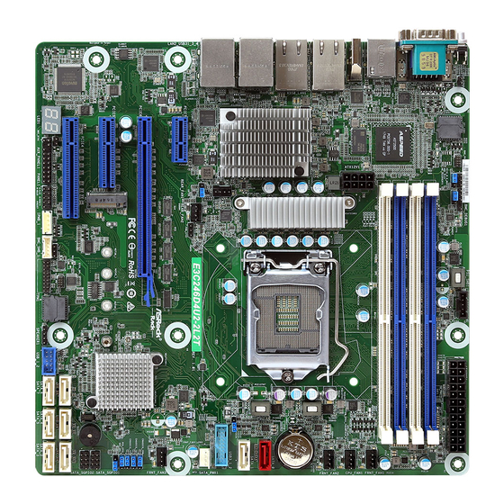
Page 13: Motherboard Layout
E3C246D4U2-2L2T / E3C242D4U2-2T 1.4 Motherboard Layout E3C246D4U2-2L2T 24.4cm (9.6 in) UID1 ATXPWR1 BMC_DIS1 ME_RECOVERY1 PSU_SMB1 DDR3_B1 (64 bit, 240-pin module) DDR4_B1 (64 bit, 288-pin module) DDR3_A1 (64 bit, 240-pin module) DDR4_B2 (64 bit, 288-pin module) DDR3_B1 (64 bit, 240-pin module) - Page 14 Description 2 x 288-pin DDR4 DIMM Slots (DDR4_A2, DDR4_B2, White) Enable/Disable BMC Jumper (BMC_DIS1) ME Recovery Jumper (ME_RECOVERY1) PSU SMBus (PSU_SMB1) ATX Power Connector (ATXPWR1) 2 x 288-pin DDR4 DIMM Slots (DDR4_A1, DDR4_B1, Blue) Front Fan Connector (FRNT_FAN1) CPU Fan Connector (CPU_FAN1) Front Fan Connector (FRNT_FAN2) SATA3 DOM Connector (SATA_0), Red* SATA3 Connector (SATA_1)
- Page 15 E3C246D4U2-2L2T / E3C242D4U2-2T Description Intelligent Platform Management Bus Header (IPMB_1) System Panel Header (PANEL1) Auxiliary Panel Header (AUX_PANEL1) Non Maskable Interrupt Button (NMI_BTN1) M.2 Socket (M2_1) (Type 2230/2242/2260/2280)* PWM Configuration Header (PWM_CFG1) Rear Fan Connector (REAR_FAN2) CPU PECI Mode Jumper (PECI1)
- Page 16 E3C242D4U2-2T 24.4cm (9.6 in) UID1 ATXPWR1 ME_RECOVERY1 BMC_DIS1 PSU_SMB1 DDR3_B1 (64 bit, 240-pin module) DDR4_B1 (64 bit, 288-pin module) DDR3_A1 (64 bit, 240-pin module) DDR4_B2 (64 bit, 288-pin module) DDR3_B1 (64 bit, 240-pin module) DDR4_A1(64 bit, 288-pin module) DDR3_A1 (64 bit, 240-pin module) DDR4_A2 (64 bit, 288-pin module) IPMI FRNT_FAN1...
- Page 17 E3C246D4U2-2L2T / E3C242D4U2-2T Description 2 x 288-pin DDR4 DIMM Slots (DDR4_A2, DDR4_B2, White) Enable/Disable BMC Jumper (BMC_DIS1) ME Recovery Jumper (ME_RECOVERY1) PSU SMBus (PSU_SMB1) ATX Power Connector (ATXPWR1) 2 x 288-pin DDR4 DIMM Slots (DDR4_A1, DDR4_B1, Blue) Front Fan Connector (FRNT_FAN1)
- Page 18 Description Auxiliary Panel Header (AUX_PANEL1) Non Maskable Interrupt Button (NMI_BTN1) M.2 Socket (M2_1) (Type 2230/2242/2260/2280)* PWM Configuration Header (PWM_CFG1) Rear Fan Connector (REAR_FAN2) CPU PECI Mode Jumper (PECI1) Rear Fan Connector (REAR_FAN1) ATX 12V Power Connector (ATX12V1) *The M.2 slot (M2_1) is shared with the SATA_0 connector. When M2_1 is populated with a M.2 SATA3 mod- ule, the Pin 7 of SATA_0 is disabled.
-
Page 19: Onboard Led Indicators
E3C246D4U2-2L2T / E3C242D4U2-2T 1.5 Onboard LED Indicators UID1 ATXPWR1 DDR3_B1 (64 bit, 240-pin module) DDR4_B1 (64 bit, 288-pin module) DDR3_A1 (64 bit, 240-pin module) DDR4_B2 (64 bit, 288-pin module) DDR3_B1 (64 bit, 240-pin module) DDR4_A1(64 bit, 288-pin module) DDR3_A1 (64 bit, 240-pin module) - Page 20 Item Status Description SB_PWR1 Green STB PWR ready FRNT_FAN1_LED1 Amber FRNT_FAN1 failed CPU_FAN1_LED1 Amber CPU_FAN1 failed FRNT_FAN2_LED2 Amber FRNT_FAN2 failed FRNT_FAN3_LED3 Amber FRNT_FAN3 failed REAR_FAN2_LED2 Amber REAR_FAN2 failed REAR_FAN1_LED1 Amber REAR_FAN1 failed BMC_LED1 Green BMC heartbeat LED...
-
Page 21: I/O Panel
E3C246D4U2-2L2T / E3C242D4U2-2T 1.6 I/O Panel E3C246D4U2-2L2T No. Description No. Description UID Switch (UID1) 10G LAN RJ-45 Port (X550_LAN1)** VGA Port (VGA1) USB 3.1 Gen2 Ports (USB31_1_2) Serial Port (COM1) 1G LAN RJ-45 Port (I210_LAN1)*** LAN RJ-45 Port (IPMI_LAN)* USB 3.1 Gen1 Ports (USB31_3_4) - Page 22 LAN Port LED Indications *There are two LED next to the LAN port. Please refer to the table below for the LAN port LED indications. ACT/LINK LED SPEED LED LAN Port Dedicated IPMI LAN Port LED Indications Activity / Link LED Speed LED Status Description...
- Page 23 E3C246D4U2-2L2T / E3C242D4U2-2T ***There are two LEDs on each LAN port. Please refer to the table below for the LAN port LED indications. SPEED LED ACT/LINK LED LAN Port 1G LAN Port LED Indications Speed LED Activity / Link LED...
-
Page 24: Block Diagram
1.7 Block Diagram... - Page 25 E3C246D4U2-2L2T / E3C242D4U2-2T...
-
Page 26: Chapter 2 Installation
Chapter 2 Installation This is a mATX form factor (9.6'' x 9.6'', 24.4 cm x 24.4 cm) motherboard. Before you install the motherboard, study the configuration of your chassis to ensure that the motherboard fits into it. Make sure to unplug the power cord before installing or removing the motherboard. Failure to do so may cause physical injuries to you and damages to motherboard components. -
Page 27: Installing The Cpu
E3C246D4U2-2L2T / E3C242D4U2-2T 2.3 Installing the CPU 1. Before you insert the 1151-Pin CPU into the socket, please check if the PnP cap is on the socket, if the CPU surface is unclean, or if there are any bent pins in the socket. Do not force to insert the CPU into the socket if above situation is found. - Page 28 Please save and replace the cover if the processor is removed. The cover must be placed if you wish to return the motherboard for after service.
-
Page 29: Installing The Cpu Fan And Heatsink
E3C246D4U2-2L2T / E3C242D4U2-2T 2.4 Installing the CPU Fan and Heatsink... -
Page 30: Installation Of Memory Modules (Dimm)
2.5 Installation of Memory Modules (DIMM) This motherboard provides four 288-pin DDR4 (Double Data Rate 4) DIMM slots, and supports Dual Channel Memory Technology. 1. For dual channel configuration, you always need to install identical (the same brand, speed, size and chip-type) DDR4 DIMM pairs. 2. - Page 31 E3C246D4U2-2L2T / E3C242D4U2-2T The DIMM only fits in one correct orientation. It will cause permanent damage to the motherboard and the DIMM if you force the DIMM into the slot at incorrect orientation.
-
Page 32: Expansion Slots (Pci Express Slots)
2.6 Expansion Slots (PCI Express Slots) There are 4 (E3C246D4U2-2L2T) / 3 (E3C242D4U2-2T) PCI Express slots on this motherboard. PCIE slot: PCIE4 (PCIe 3.0 x8 slot) is used for PCI Express x8 lane width cards. PCIE5 (PCIe 3.0 x4 slot) is used for PCI Express x4 lane width cards. -
Page 33: Jumper Setup
E3C246D4U2-2L2T / E3C242D4U2-2T 2.7 Jumper Setup The illustration shows how jumpers are setup. When the jumper cap is placed on the pins, the jumper is “Short”. If no jumper cap is placed on the pins, the jumper is “Open”. The illustration shows a 3-pin jumper whose pin1 and pin2 are “Short”... - Page 34 Chassis ID0 Jumper (3-pin CHASSIS_ID0) Chassis ID1 Jumper (3-pin CHASSIS_ID1) Chassis ID2 Jumper (3-pin CHASSIS_ID2) Board Level SKU (Default) Reserved for system level Chassis ID0 Jumper (3-pin CHASSIS_ID0) Chassis ID1 Jumper (3-pin CHASSIS_ID1) Chassis ID2 Jumper (3-pin CHASSIS_ID2) Reserved for system level Reserved for system level Chassis ID0 Jumper (3-pin CHASSIS_ID0)
- Page 35 E3C246D4U2-2L2T / E3C242D4U2-2T SATA DOM Power Jumper (3-pin SATAPWR1) SATA DOM (SATA_0) SATA DOM (SATA_0) does requires 5V power supply NOT require 5V power sup- ply (Default) Consult the documentation that comes with your SATA DOM and check whether or not Pin 7 requires 5V power supply.
-
Page 36: Onboard Headers And Connectors
2.8 Onboard Headers and Connectors Onboard headers and connectors are NOT jumpers. Do NOT place jumper caps over these headers and connectors. Placing jumper caps over the headers and connectors will cause permanent damage to the motherboard. System Panel Header C onnec t t he power sw itch, PLED+ PLED-... - Page 37 E3C246D4U2-2L2T / E3C242D4U2-2T Auxiliary Panel Header This header supports multiple (18-pin AUX PANEL_1) functions on the front panel, including the front panel SMB, internet status indicator and chassis intrusion pin. A. Front panel SMBus connecting pin (6-1 pin FPSMB) This header allows you to connect SMBus (System Management Bus) equipment. It can be used for communication between peripheral equipment in the system, which has slower transmission rates, and power management equipment.
- Page 38 SATA_0 connector. When M2_1 is (SATA_5) populated with a M.2 SATA3 module, SA TA_7 SA TA_3 the Pin 7 of SATA_0 is disabled. E3C246D4U2-2L2T only: (SATA_6) (SATA_7) Serial ATA3 DOM The SATA3 DOM connector Connector supports both a SATA DOM...
- Page 39 3-Pin CPU fan, CPU_FAN_SPEED FA N_SPEED_CONTROL please connect it to Pin 1-3. *For more details, please refer to the Cooler QVL list on the ASRock Rack website. Front and Rear Fan Please connect fan cables to the Connectors...
- Page 40 TPM Header This connector supports (17-pin TPM1) Trusted Platform Module (TPM) system, which can securely store keys, digital certificates, passwords, and data. A TPM system also helps enhance network security, protects digital identities, and ensures platform integrity. Serial General Purpose The headers suppor t Seria l SCLOCK SLOAD...
- Page 41 E3C246D4U2-2L2T / E3C242D4U2-2T Intelligent Platform This 4-pin connector is used No connect Management Bus Header to provide a cabled base-board (4-pin IPMB_1) or front panel connection for value added features and 3rd- IPMB_SCL IPMB_SDA party add-in cards, such as Emergency Management cards, t h a t p r o v i d e m a n a g e m e n t features using the IPMB.
-
Page 42: Dr. Debug (E3C246D4U2-2L2T Only)
2.9 Dr. Debug (E3C246D4U2-2L2T only) Dr. Debug is used to provide code information, which makes troubleshooting even easier. Please see the diagrams below for reading the Dr. Debug codes. Code Description Please check if the CPU is installed correctly and then clear CMOS. -
Page 43: Unit Identification Purpose Led/Switch
E3C246D4U2-2L2T / E3C242D4U2-2T 2.10 Unit Identification purpose LED/Switch With the UID button, You are able to locate the server you’re working on from behind a rack of servers. Unit Identification When the UID button on the purpose LED/Switch front or rear panel is pressed,... -
Page 44: Dua Lan And Teaming Operation Guide
2.12 Dua LAN and Teaming Operation Guide Dual LAN with Teaming enabled on this motherboard allows two single connections to act as one single connection(s) for twice the transmission bandwidth, making data transmission more effective and improving the quality of transmission of distant images. -
Page 45: M.2_Ssd (Ngff) Module Installation Guide
E3C246D4U2-2L2T / E3C242D4U2-2T 2.13 M.2_SSD (NGFF) Module Installation Guide The M.2, also known as the Next Generation Form Factor (NGFF), is a small size and versatile card edge connector that aims to replace mPCIe and mSATA. The M.2_SSD (NGFF) Socket 3 can accommodate either a M.2 SATA3 6.0 Gb/s module or a M.2 PCI Express module up to Gen 3 x4 (32Gb/s). - Page 46 Step 3 Move the standoff based on the module type and length. The standoff is placed at the nut location D by default. Skip Step 3 and 4 and go straight to Step 5 if you are going to use the default nut. Otherwise, release the standoff by hand.
-
Page 47: Chapter 3 Uefi Setup Utility
E3C246D4U2-2L2T / E3C242D4U2-2T Chapter 3 UEFI Setup Utility 3.1 Introduction Th is section explains how to use the UEFI SETUP UTILITY to confi gure your system. Th e UEFI chip on the motherboard stores the UEFI SETUP UTILITY. You may run the UEFI SETUP UTILITY when you start up the computer. -
Page 48: Navigation Keys
3.1.2 Navigation Keys Please check the following table for the function description of each navigation key. Navigation Key(s) Function Description Moves cursor left or right to select Screens Moves cursor up or down to select items + / - To change option for the selected items <Tab>... -
Page 49: Main Screen
E3C246D4U2-2L2T / E3C242D4U2-2T 3.2 Main Screen Once you enter the UEFI SETUP UTILITY, the Main screen will appear and display the system overview. The Main screen provides system overview information and allows you to set the system time and date. -
Page 50: Advanced Screen
3.3 Advanced Screen In this section, you may set the configurations for the following items: CPU Configuration, DRAM Configuration, Chipset Configuration, Storage Configuration, ACPI Configura- tion, USB Configuration, Super IO Configuration, Serial Port Console Redirection, H/W Monitor, Runtime Errpr Logging, Intel SPS Configuration, Intel(R) Bios Guard Technol- ogy and Instant Flash. -
Page 51: Cpu Configuration
E3C246D4U2-2L2T / E3C242D4U2-2T 3.3.1 CPU Configuration Software Guard Extensions (SGX) Use this item to enable or disable Software Controlled Software Guard Extensions (SGX). SGX Launch Control Policy Software Guard Extensions (SGX) Launch Control Policy. Options are: Intel Locked - Select Intel's Launch Enclave. - Page 52 CPU C3 State Support Enable C3 deep sleep state for lower power consumption. CPU C6 State Support Enable C6 deep sleep state for lower power consumption. CPU C7 State Support Enable C7 deep sleep state for lower power consumption. Package C State Support Enable CPU, PCIe, Memory, Graphics C State Support for power saving.
- Page 53 E3C246D4U2-2L2T / E3C242D4U2-2T Intel Turbo Boost Technology Use this item to enable or disable Intel Turbo Boost Mode Technology. Turbo Boost Mode allows processor cores to run faster than marked frequency in specific conditions. The de- fault value is [Enabled].
-
Page 54: Dram Configuration
3.3.2 DRAM Configuration DRAM Frequency If [Auto] is selected, the motherboard will detect the memory module(s) inserted and assign the appropriate frequency automatically. -
Page 55: Chipset Configuration
E3C246D4U2-2L2T / E3C242D4U2-2T 3.3.3 Chipset Configuration Primary Graphics Adapter If PCI Express graphics card is installed on the motherboard, you may use this option to select PCI Express or Onboard as the primary graphics adapter. Onboard VGA Use this to enable or disable the Onboard VGA function. The default value is [Auto]. - Page 56 PCIE7 Link Speed This allows you to select PCIE7 Link Speed. The default value is [Auto]. PCIE7 ASPM Support This option enables or disables the ASPM support for all CPU downstream devices. PCIE4 Link Width This allows you to select PCIE4 Link Width. The default value is [Auto]. PCIE4 Link Speed This allows you to select PCIE4 Link Speed.
-
Page 57: Storage Configuration
E3C246D4U2-2L2T / E3C242D4U2-2T 3.3.4 Storage Configuration Hard Disk S.M.A.R.T. S.M.A.R.T stands for Self-Monitoring, Analysis, and Reporting Technology. It is a monitoring system for computer hard disk drives to detect and report on various indicators of reliability. SATA Storage Configuration Use this item to enable or disable SATA Controllers. -
Page 58: Acpi Configuration
3.3.5 ACPI Configuration PCIE Devices Power On Allow the system to be waked up by a PCIE device and enable wake on LAN. Ring-In Power On Use this item to enable or disable Ring-In signals to turn on the system from the powersoft- off mode. -
Page 59: Usb Configuration
E3C246D4U2-2L2T / E3C242D4U2-2T 3.3.6 USB Configuration Legacy USB Support Enable or disable Legacy OS Suppor t for USB 2.0 dev ices. If you encounter USB compatibility issues it is recommended to disable legacy USB support. Select UEFI Setup Only to support USB devices under the UEFI setup and Windows/Linux... -
Page 60: Super Io Configuration
3.3.7 Super IO Configuration Serial Port 1 Configuration Use this item to set parameters of COM1. Serial Port Use this item to enable or disable the serial port (COM). Change Settings Use this item to select an optimal setting for Super IO device. SOL Port Configuration Use this item to set parameters of SOL. -
Page 61: Serial Port Console Redirection
E3C246D4U2-2L2T / E3C242D4U2-2T 3.3.8 Serial Port Console Redirection COM1 Console Redirection Use this option to enable or disable Console Redirection. If this item is set to Enabled, you can select a COM Port to be used for Console Redirection. Console Redirection Settings Use this option to configure Console Redirection Settings, and specify how your computer and the host computer to which you are connected exchange information. - Page 62 Bits Per Second Use this item to select the serial port transmission speed. The speed used in the host computer and the client computer must be the same. Long or noisy lines may require lower transmission speed. The options include [9600], [19200], [38400], [57600] and [115200]. Data Bits Use this item to set the data transmission size.
- Page 63 E3C246D4U2-2L2T / E3C242D4U2-2T Legacy Console Redirection Legacy Console Redirection Settings Use this option to configure Legacy Console Redirection Settings, and specify how your computer and the host computer to which you are connected exchange information. Redirection COM Port Select a COM port to display redirection of Legacy OS and Legacy OPROM Messages.
- Page 64 transmission speed. The options include [9600], [19200], [57600] and [115200]. Flow Control Use this item to set the f low control to prevent data loss from buffer overf low. When sending data, if the receiving buffers are full, a "stop" signal can be sent to stop the data flow.
-
Page 65: H/W Monitor
E3C246D4U2-2L2T / E3C242D4U2-2T 3.3.9 H/W Monitor In this section, it allows you to monitor the status of the hardware on your system, includ- ing the parameters of the CPU temperature, motherboard temperature, CPU fan speed, chassis fan speed, and the critical voltage. - Page 66 FRNT_FAN 3 This allows you to set the front fan 3’s speed. The default value is [Smart Fan]. Smart Fan Control This allows you to set the Smart fan’s level speed. Smart Fan Duty Control Smart Fan Duty x (x means 1 to 11 stage) This allows you to set duty cycle for each stage.
-
Page 67: Runtime Error Logging
E3C246D4U2-2L2T / E3C242D4U2-2T 3.3.10 Runtime Error Logging WHEA Support Use this item to enable or disable Windows Hardware Error Architecture. Runtime Error Logging System Enabling Use this item to enable or disable System Error feature. When it is set to [Enabled], you can configure Memory Error and PCIE Error log features. -
Page 68: Intel Sps Configuration
3.3.11 Intel SPS Configuration SPS screen displays the Intel SPS Configuration information, such as Operational Firmware Version and Firmware State. -
Page 69: Intel(R) Bios Guard Technology
E3C246D4U2-2L2T / E3C242D4U2-2T 3.3.12 Intel(R) Bios Guard Technology Intel Bios Guard Support Use this item to enable or disable Intel Bios Guard Support. -
Page 70: Instant Flash
3.3.13 Instant Flash Instant Flash is a UEFI flash utility embedded in Flash ROM. This convenient UEFI update tool allows you to update system UEFI without entering operating systems ® first like MS-DOS or Windows . Just save the new UEFI file to your USB flash drive, floppy disk or hard drive and launch this tool, then you can update your UEFI only in a few clicks without preparing an additional floppy diskette or other compli- cated flash utility. -
Page 71: Server Mgmt
E3C246D4U2-2L2T / E3C242D4U2-2T 3.4 Server Mgmt Wait For BMC Wait For BMC response for specified time out. In PILOTII, BMC starts at the same time when BIOS starts during AC power ON. It takes around 30 seconds to initialize Host to BMC interfaces. -
Page 72: System Event Log
3.4.1 System Event Log SEL Components Change this to enable ro disable all features of System Event Logging during boot. Erase SEL Use this to choose options for earsing SEL. When SEL is Full Use this to choose options for reactions to a full SEL. Log EFI Status Codes Use this item to disable the logging of EFI Status Codes or log only error code or only progress or both. -
Page 73: Bmc Network Configuration
E3C246D4U2-2L2T / E3C242D4U2-2T 3.4.2 BMC Network Configuration BMC Out of Band Access Use this item to enable or disable BMC Out of Band Access. Lan Channel (Failover) Manual Setting IPMI LAN If [No] is selected, the IP address is assigned by DHCP. If you prefer using a static IP address, toggle to [Yes], and the changes take effect after the system reboots. - Page 74 The default login information for the IPMI web interface is: Username: admin Password: admin For more instructions on how to set up remote control environment and use the IPMI man- agement platform, please refer to the IPMI Configuration User Guide or go to the Support website at: http://www.asrockrack.com/support/faq.asp...
-
Page 75: Security
E3C246D4U2-2L2T / E3C242D4U2-2T 3.5 Security In this section, you may set or change the supervisor/user password for the system. For the user password, you may also clear it. Supervisor Password Set or change the password for the administrator account. Only the administrator has authority to change the settings in the UEFI Setup Utility. -
Page 76: Key Management
3.5.1 Key Management In this section, expert users can modify Secure Boot Policy variables without full authenti- cation. Factory Key Provision Install factory default Secure Boot keys after the platform reset and while the System is in Setup mode. Install Default Secure Boot Keys Please install default secure boot keys if it’s the first time you use secure boot. - Page 77 E3C246D4U2-2L2T / E3C242D4U2-2T Remove 'UEFI CA' from DB Device Guard ready system must not list ‘Microsoft UEFI CA’ Certificate in Autho- rized Signature database (db). Restore DB defaults Restore DB variable to factory defaults. Platform Key(PK) Enroll Factory Defaults or load certificates from a file: 1.
- Page 78 1. Public Key Certificate in: a) EFI_SIGNATURE_LIST b) EFI_CERT_X509 (DER encoded) c) EFI_CERT_RSA2048 (bin) d) EFI_CERT_SHA256, 384, 512 2. Authenticated UEFI Variable 3. EFI PE/COFF Image(SHA256) Key Source: Factory, External, Mixed Forbidden Signatures Enroll Factory Defaults or load certificates from a file: 1.
- Page 79 E3C246D4U2-2L2T / E3C242D4U2-2T Key Source: Factory, External, Mixedt OsRecovery Signatures Enroll Factory Defaults or load certificates from a file: 1. Public Key Certificate in: a) EFI_SIGNATURE_LIST b) EFI_CERT_X509 (DER encoded) c) EFI_CERT_RSA2048 (bin) d) EFI_CERT_SHA256, 384, 512 2. Authenticated UEFI Variable 3.
-
Page 80: Boot Screen
3.6 Boot Screen In this section, it will display the available devices on your system for you to configure the boot settings and the boot priority. Boot Option #1 Use this item to set the system boot order. Boot Option Filter This option controls Legacy/UEFI ROMs priority. - Page 81 E3C246D4U2-2L2T / E3C242D4U2-2T Full Screen Logo Use this item to enable or disable OEM Logo. The default value is [Enabled]. AddOn ROM Display Use this option to adjust AddOn ROM Display. If you enable the option “Full Screen Logo” but you want to see the AddOn ROM information when the system boots, please select...
-
Page 82: Csm Parameters
3.6.1 CSM Parameters Enable to launch the Compatibility Support Module. Please do not disable unless you’re running a WHCK test. If you are using Windows Server 2012 R2 or later ver- sions 64-bit UEFI and all of your devices support UEFI, you may also disable CSM for faster boot speed. - Page 83 E3C246D4U2-2L2T / E3C242D4U2-2T PCIE5 Slot OpROM To select Slot Storage and Network Option ROM policy. In Auto option, the default is Dis- abled with NVMe device, but it is Legacy with other devices. (This item can’t select Video Option ROM policy.) PCIE6 Slot OpROM To select Slot Storage and Network Option ROM policy.
-
Page 84: Event Logs
3.7 Event Logs Change Smbios Event Log Settings This allows you to configure the Smbios Event Log Settings. When entering the item, you will see the followings: Smbios Event Log Use this item to enable or disable all features of the SMBIOS Event Logging during system boot. - Page 85 E3C246D4U2-2L2T / E3C242D4U2-2T entries which utilize a multiple-event counter. The value ranges from 0 to 99 minutes. View Smbios Event Log Press <Enter> to view the Smbios Event Log records. All values changed here do not take effect until computer is restarted.
-
Page 86: Exit Screen
3.8 Exit Screen Save Changes and Exit When you select this option, the following message “Save configuration changes and exit setup?” will pop-out. Press <F10> key or select [Yes] to save the changes and exit the UEFI SETUP UTILITY. Discard Changes and Exit When you select this option, the following message “Discard changes and exit setup?”... -
Page 87: Chapter 4 Software Support
4.2.4 Contact Information If you need to contact ASRock Rack or want to know more about ASRock Rack, welcome to visit ASRock Rack’s website at http://www.ASRockRack.com; or you may contact your... -
Page 88: Chapter 5 Troubleshooting
Chapter 5 Troubleshooting 5.1 Troubleshooting Procedures Follow the procedures below to troubleshoot your system. Always unplug the power cord before adding, removing or changing any hardware com- ponents. Failure to do so may cause physical injuries to you and damages to motherboard components. - Page 89 1. Verify if the battery on the motherboard provides ~3VDC. Install a new battery if it does not. 2. Confirm whether your power supply provides adaquate and stable power. Other problems... 1. Try searching keywords related to your problem on ASRock Rack’s FAQ page: http://www.asrockrack.com/support...
-
Page 90: Technical Support Procedures
5.2 Technical Support Procedures If you have tried the troubleshooting procedures mentioned above and the problems are still unsolved, please contact ASRock Rack’s technical support with the following information: 1. Your contact information 2. Model name, BIOS version and problem type.
Need help?
Do you have a question about the E3C246D4U2-2L2T and is the answer not in the manual?
Questions and answers