
Related Manuals for Sun Microsystems Fire 880


Summary of Contents for Sun Microsystems Fire 880
- Page 1 ™ Sun Fire 880 Server Owner’s Guide Sun Microsystems, Inc. 901 San Antonio Road Palo Alto, CA 94303-4900 U.S.A. 650-960-1300 Part No. 806-6592-11 August 2001 Revision A...
- Page 2 U.S. and other countries. Products bearing SPARC trademarks are based upon an architecture developed by Sun Microsystems, Inc. The OPEN LOOK and Sun™ Graphical User Interface was developed by Sun Microsystems, Inc. for its users and licensees. Sun acknowledges the pioneering efforts of Xerox in researching and developing the concept of visual or graphical user interfaces for the computer industry. Sun holds a non-exclusive license from Xerox to the Xerox Graphical User Interface, which license also covers Sun’s licensees who implement OPEN...
- Page 3 Networking connections can be made using unshielded twisted-pair (UTP) cables. Modifications: Any modifications made to this device that are not approved by Sun Microsystems, Inc. may void the authority granted to the user by the FCC to operate this equipment.
- Page 4 ICES-003 Class B Notice - Avis NMB-003, Classe B This Class B digital apparatus complies with Canadian ICES-003. Cet appareil numérique de la classe B est conforme à la norme NMB-003 du Canada. Sun Fire 880 Server Owner’s Guide • August 2001...
- Page 5 BSMI Class A Notice The following statement is applicable to products shipped to Taiwan and marked as Class A on the product compliance label. Regulatory Compliance Statements...
- Page 6 Sun Fire 880 Server Owner’s Guide • August 2001...
- Page 7 Declaration of Conformity Compliance Model Number: Product Family Name: Sun Fire 880 European Union This equipment complies with the following requirements of the EMC Directive 89/336/EEC: EN55022:1998/CISPR22:1997 Class A EN55024:1998 Required Limits (as applicable): EN61000-4-2 4 kV (Direct), 8 kV (Air)
- Page 8 Sun Fire 880 Server Owner’s Guide • August 2001...
-
Page 9: Table Of Contents
About Reliability, Availability, and Serviceability Features 14 Setting Up the System 23 About the Parts Shipped to You 24 How to Install the Sun Fire 880 Server 25 How to Open the Side Doors 29 How to Avoid Electrostatic Discharge 31... - Page 10 About Sun Fire 880 Mass Storage Features 92 About the Mass Storage Subsystem Components 94 About the FC-AL Disk Backplanes 95 About Internal Disk Drives 97 About FC-AL Host Adapters 99 About FC-AL Device Addresses 101 Sun Fire 880 Server Owner’s Guide • August 2001...
- Page 11 Configuring Network Interfaces 103 About Network Interface Options 104 About Redundant Network Interfaces 105 How to Configure the Primary Network Interface 106 How to Configure Additional Network Interfaces 108 How to Attach a Fiber-Optic Gigabit Ethernet Cable 112 How to Attach a Twisted-Pair Ethernet Cable 114 How to Select the Boot Device 116 Configuring System Firmware 119 About OpenBoot Environmental Monitoring 120...
- Page 12 Connector Pinouts 187 Reference for Serial Port A and B Connectors 188 Reference for the USB Connectors 189 Reference for the Twisted-Pair Ethernet Connector 190 Reference for the RSC Ethernet Connector 191 Sun Fire 880 Server Owner’s Guide • August 2001...
- Page 13 Reference for the RSC Modem Connector 192 Reference for the RSC Serial Connector 193 System Specifications 195 Reference for Physical Specifications 196 Reference for Electrical Specifications 196 Reference for Environmental Requirements 197 Reference for Agency Compliance Specifications 198 Reference for Clearance and Service Access Specifications 198 Safety Precautions 201 Contents xiii...
- Page 14 Sun Fire 880 Server Owner’s Guide • August 2001...
-
Page 15: Preface
Sun Fire 880 server. Look at the titles of the modules and you’ll find the cue words that direct you to the categories of questions and answers, such as: How to . - Page 16 To delete a file, type rm filename. with a real name or value Shell Prompts Shell Prompt C shell machine-name% C shell superuser machine-name# Bourne shell and Korn shell Bourne shell and Korn shell superuser xvi Sun Fire 880 Server Owner’s Guide • August 2001...
- Page 17 Solaris System Administrator AnswerBook Platform Notes: The eri FastEthernet Device Driver Platform Notes: The Sun GigabitEthernet Device Driver Platform Notes: Using luxadm Software Sun Fire 880 Dynamic Reconfiguration User’s Guide OpenBoot Command Reference Manual OpenBoot Quick Reference Remote System Monitoring Sun Remote System Control (RSC) User’s Guide...
- Page 18 Sun is interested in improving its documentation and welcomes your comments and suggestions. You can email your comments to Sun at: docfeedback@sun.com Please include the part number (806-6592-11) of your document in the subject line of your email. xviii Sun Fire 880 Server Owner’s Guide • August 2001...
-
Page 19: System Overview
C H A P T E R System Overview This chapter introduces you to the Sun Fire 880 server and describes some of its features. The following information is covered in this chapter: “About the Sun Fire 880 Server” on page 2 “Locating Front Panel Features”... -
Page 20: About The Sun Fire 880 Server
About the Sun Fire 880 Server The Sun Fire 880 server is a high-performance, shared memory, symmetric multiprocessing server system that supports up to eight Sun UltraSPARC™ III processors. The UltraSPARC III processor implements the SPARC V9 Instruction Set Architecture (ISA) and the Visual Instruction Set (VIS™) extensions that accelerate multimedia, networking, encryption, and Java™... - Page 21 SCSI, FC-AL, and other types of devices are included in the Solaris operating environment. The Sun Fire 880 server provides front panel access to three mounting bays for 5.25-inch half-height (1.6-inch) removable media devices. One of the bays houses a SCSI DVD-ROM drive, which comes standard in all system configurations.
- Page 22 RSC provides remote system administration for geographically distributed or physically inaccessible systems. RSC software works in conjunction with the RSC card included in all Sun Fire 880 servers. The RSC card runs independently of the host server, and operates off of 5-volt standby power from the system’s power supplies.
- Page 23 For more information about the power supplies, see “About Power Supplies” on page 73. The Sun Fire 880 server can be installed in any standard Electronic Industries Association (EIA) 310-compliant 19-inch (48.3 cm) rack with at least 17 rack units (29.8 inches, 75.6 cm) of available vertical mounting space and sufficient...
-
Page 24: Locating Front Panel Features
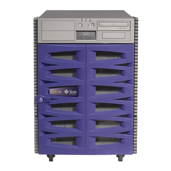
Security keyswitch DVD-ROM drive Status and control panel Disk drives Disk drive LEDs For information about front panel controls and indicators, see “About the Status and Control Panel” on page 10. Sun Fire 880 Server Owner’s Guide • August 2001... - Page 25 Access to the system’s internal disk drives is through a large hinged door at the front of the system. The front door features a keylock for added security. When the key is in the horizontal position, the door is unlocked. Make sure that the key is in the horizontal position before you close the door.
-
Page 26: Locating Rear Panel Features
PCI slot 1 PCI slot 0 USB B USB A TPE Fast Ethernet Serial port A/B interface RSC card Grounding screw Power supply 0 Power supply 2 (optional) Power supply 1 Sun Fire 880 Server Owner’s Guide • August 2001... - Page 27 A grounding screw is located just above the center power supply. When installing a Sun Fire 880 server into a rack, or connecting the server to an external storage array, be sure to connect an appropriate grounding strap between the server’s grounding screw and the grounding screw on the rack enclosure or external storage array.
-
Page 28: About The Status And Control Panel
The following figure shows the status and control panel. System Fault LED OK-to-Remove LED Power/OK LED Power button Security keyswitch Power Fault Attention Attention Right Side Left Side Thermal Thermal Fault Fault Disk Fault Sun Fire 880 Server Owner’s Guide • August 2001... - Page 29 LED Status Indicators Several LED status indicators provide general system status, alert you to system problems, and help you to determine the location of system faults: At the top of the status and control panel, three general status LEDs provide a snapshot of the system status.
- Page 30 Note – Whenever possible, you should use the graceful shutdown method. Forcing an immediate hardware shutdown may cause disk drive corruption and loss of data. Use this method only as a last resort. Sun Fire 880 Server Owner’s Guide • August 2001...
- Page 31 Security Keyswitch The four-position security keyswitch controls the power-on modes of the system and prevents unauthorized users from powering off the system or reprogramming system firmware. The following table describes the function of each keyswitch setting. Position Icon Description Normal This setting enables the system Power button to power the system on or off.
-
Page 32: About Reliability, Availability, And Serviceability Features
Together, reliability, availability, and serviceability features provide for near continuous system operation. To deliver high levels of reliability, availability and serviceability, the Sun Fire 880 system offers the following features: Hot-pluggable disk drives and PCI cards... - Page 33 Hot-Pluggable Disk Drives and PCI Cards Sun Fire 880 system hardware is designed to support hot-plugging of internal disk drives and PCI cards. With the proper software support, you can install or remove these components while the system is running. Hot-plug technology significantly increases the system’s serviceability and availability, by providing the ability to:...
- Page 34 For additional details, see “About Fan Trays” on page 75. Environmental Monitoring and Control The Sun Fire 880 system features an environmental monitoring subsystem designed to protect against: Extreme temperatures Lack of adequate air flow through the system...
- Page 35 For more information about error messages generated by the environmental monitoring subsystem, see the Sun Fire 880 Server Service Manual. For more information about system LEDs, see Chapter 8.
- Page 36 For additional details, see Chapter 6. Hardware Watchdog Mechanism To detect and respond to system hang conditions, the Sun Fire 880 system features a hardware watchdog mechanism—a hardware timer that is continually reset as long as the operating system is running. In the event of a system hang, the operating system is no longer able to reset the timer.
- Page 37 RSC provides remote system administration for geographically distributed or physically inaccessible systems. The RSC software works with the RSC card on the Sun Fire 880 system I/O board. The RSC card provides modem and private Ethernet connections to a remote console, and a serial connection to a local alphanumeric terminal.
- Page 38 In addition to providing ECC protection for data, the system offers parity protection on all system address buses. Parity protection is also used on the PCI and SCSI buses, and in the UltraSPARC CPU’s internal and external cache. Sun Fire 880 Server Owner’s Guide • August 2001...
- Page 39 Management Center software provides a variety of continuous system monitoring capabilities. It enables you to monitor system hardware status and operating system performance of your server. For more information about diagnostic tools, see the Sun Fire 880 Server Service Manual. Chapter 1 System Overview...
- Page 40 Sun Fire 880 Server Owner’s Guide • August 2001...
-
Page 41: Setting Up The System
C H A P T E R Setting Up the System This chapter describes what you need to do to get the Sun Fire 880 server up and running. Where software is involved, this chapter explains some of what you need to do, and points you to the appropriate software manuals for the rest. -
Page 42: About The Parts Shipped To You
About the Parts Shipped to You Sun Fire 880 systems are “configured-to-order,” which means that most internal options are pre-installed at the factory. However, if you ordered options that are not factory-installed (such as a monitor), these will be shipped to you separately. -
Page 43: How To Install The Sun Fire 880 Server
How to Install the Sun Fire 880 Server Before You Begin The Sun Fire 880 server is a general-purpose server, which you can use for many types of applications. Exactly how you set up your machine depends on what you want it to do. - Page 44 Note – All internal options (except disk drives and power supplies) must be installed only by qualified service personnel. Installation procedures for these components are covered in the Sun Fire 880 Server Service Manual, which is included on the Sun Fire 880 Documentation CD.
- Page 45 “About Setting Up a Console” on page 45. 6. Prepare the network interface(s). The Sun Fire 880 server provides two on-board Ethernet interfaces as part of the standard configuration—one Fast Ethernet interface and one Gigabit Ethernet interface. A variety of supported PCI cards can provide connections to additional Ethernet or other network types.
- Page 46 Solaris media kit for a complete listing of included software and detailed installation instructions. 11. Load online documentation from the Sun Fire 880 Documentation CD. You can copy the CD contents to a local or network disk drive, or view the documentation directly from the CD.
-
Page 47: How To Open The Side Doors
How to Open the Side Doors What to Do 1. Use the system key to unlock the door. 2. Swing the side door open. Chapter 2 Setting Up the System... - Page 48 3. To remove the door completely, open the door 90 degrees and lift it up until its mounting pins clear the hinge brackets on the rear panel. What Next You are now ready to install, remove, or replace components inside the system chassis. Sun Fire 880 Server Owner’s Guide • August 2001...
-
Page 49: How To Avoid Electrostatic Discharge
Use the following procedure to prevent static damage whenever you are accessing any of the internal components of the system. Note – Internal access to the Sun Fire 880 system is restricted to qualified service personnel only. Installation procedures for internal components are covered in the Sun Fire 880 Server Service Manual, which is included on the Sun Fire 880 Documentation CD. - Page 50 Attach one end of the strap to the system chassis sheet metal, and attach the other end to your wrist. Refer to the instructions that come with the strap. 4. Detach both ends of the strap after you complete the installation or service procedure. Sun Fire 880 Server Owner’s Guide • August 2001...
-
Page 51: How To Install A Disk Drive
How to Install a Disk Drive Before You Begin The system’s disk drive hot-plug feature lets you install a disk drive without shutting down the operating system or turning off the system power. For more information, see: “About Internal Disk Drives” on page 97 “About Hot-Pluggable and Hot-Swappable Components”... - Page 52 11. Close the front door and lock it, if necessary. 12. If you are performing a hot-plug installation, complete the software part of the installation procedure. See “About Hot-Pluggable and Hot-Swappable Components” on page 144. Sun Fire 880 Server Owner’s Guide • August 2001...
- Page 53 If you installed a disk drive as part of the initial system installation procedure, resume the procedure at Step 4. See: “How to Install the Sun Fire 880 Server” on page 25 If the operating system has been installed already, and you added the disk drive while the system was powered off, you need to perform a reconfiguration boot so that your system is able to recognize the new disk drive(s).
-
Page 54: How To Remove A Disk Drive
4. If you are not performing a hot-plug operation, halt the operating system and power off the system. See “How to Power Off the System” on page 53. 5. Attach an antistatic wrist strap to a metal surface inside the system chassis. Sun Fire 880 Server Owner’s Guide • August 2001... - Page 55 6. Using your thumb or forefinger, push the drive latch upward to release the drive handle. Swing the handle away from the drive until you feel the drive connector disengage from the backplane. Do not use excessive force. Caution – If you are hot-plugging the disk drive, after disconnecting it from the backplane, allow 30 seconds or so for the drive to spin down completely before removing it from the system.
- Page 56 A reconfiguration boot is required in order for the operating system to recognize the configuration change. See: “How to Initiate a Reconfiguration Boot” on page 55 Sun Fire 880 Server Owner’s Guide • August 2001...
-
Page 57: How To Install A Power Supply
How to Install a Power Supply Before You Begin If you are installing a redundant power supply, it is not necessary to shut down and power off the system. For more information, see: “About Power Supplies” on page 73 “About Hot-Pluggable and Hot-Swappable Components” on page 144 Note –... - Page 58 5. Connect the AC power cord to both the power supply and a dedicated AC power outlet. Insert the female end of the power cord through the strain-relief tie-wrap loop located to the right of the supply. Tighten the tie-wrap to secure the connection. Sun Fire 880 Server Owner’s Guide • August 2001...
- Page 59 If you installed a power supply as part of the initial system installation procedure, resume the procedure at Step 4. See: “How to Install the Sun Fire 880 Server” on page 25 If the operating system has been installed already, and you added a power supply while the system was powered off, you need to perform a reconfiguration boot.
-
Page 60: How To Remove A Power Supply
5. Grasp the handle and carefully pull the power supply out of its bay. Place one hand beneath the supply to support it as you slide it out of the bay. Sun Fire 880 Server Owner’s Guide • August 2001... - Page 61 Note – When hot-swapping a power supply, do not disengage and reengage the supply in rapid succession. Rapid seating and unseating of a power supply will result in false error conditions. After removing a supply, wait for an acknowledgement message on the system console before installing a new supply; otherwise, the environmental monitoring software will not recognize the new device and false error conditions will result.
- Page 62 What Next To replace a power supply, complete this task: “How to Install a Power Supply” on page 39 Sun Fire 880 Server Owner’s Guide • August 2001...
-
Page 63: About Setting Up A Console
About Setting Up a Console To install your server or to diagnose problems, you need some way to enter system commands and view system output. There are four ways to do this. 1. Attach an ACSII character terminal to serial port A. You can attach a simple terminal to serial port A. -
Page 64: How To Attach An Alphanumeric Terminal
Solaris operating environment. The operating environment must be installed prior to setting up an RSC console. What to Do 1. Connect a DB-25 null modem serial cable or a DB-25 serial cable and null modem adapter to the terminal’s serial port. Sun Fire 880 Server Owner’s Guide • August 2001... - Page 65 2. Connect the opposite end of the cable to the system’s serial port connector or to serial port A on the serial splitter cable. 3. Connect the terminal’s power cable to an AC outlet. 4. Set the terminal to receive: At 9600 baud An 8-bit signal with no parity and 1 stop bit See the documentation accompanying your terminal for more information.
-
Page 66: How To Configure A Local Graphics Console
68. Note – PCI cards must be installed only by qualified service personnel. Installation procedures for PCI cards are covered in the Sun Fire 880 Server Service Manual, which is included on the Sun Fire 880 Documentation CD. Sun Fire 880 Server Owner’s Guide • August 2001... - Page 67 2. Attach the monitor video cable to the graphic card’s video port. Tighten the thumbscrews to secure the connection. 3. Connect the monitor’s power cord to an appropriate AC power outlet. 4. Attach the keyboard cable to one of the system’s USB ports. Chapter 2 Setting Up the System...
- Page 68 5. Attach the mouse cable to the system’s remaining USB port, or to a USB port on the keyboard, if applicable. What Next You can now issue system commands and view system messages. Continue with your installation or diagnostic procedure as needed. Sun Fire 880 Server Owner’s Guide • August 2001...
-
Page 69: How To Power On The System
How to Power On the System Before You Begin Do not use this power-on procedure if the operating system is already installed and you have just added a new internal option or external storage device. To power on the system after adding one of these options, see: “How to Initiate a Reconfiguration Boot”... - Page 70 “How to Power Off the System” on page 53 “How to Power On the System” on page 51 For information about system troubleshooting and diagnostics, see the Sun Fire 880 Server Service Manual. Sun Fire 880 Server Owner’s Guide • August 2001...
-
Page 71: How To Power Off The System
How to Power Off the System What to Do 1. Notify users that the system will be powered down. 2. Back up the system files and data, if necessary. 3. Ensure that the front panel keyswitch is in the Normal or Diagnostics position. 4. - Page 72 The Forced Off position is the only keyswitch position that prevents an RSC user from restarting the system. 7. Remove the key from the keyswitch and keep it in a secure place. Sun Fire 880 Server Owner’s Guide • August 2001...
-
Page 73: How To Initiate A Reconfiguration Boot
How to Initiate a Reconfiguration Boot After installing any new internal option or external storage device, you must perform a reconfiguration boot so that the operating system is able to recognize the newly installed device(s). In addition, if you remove any device and do not install a replacement device prior to rebooting the system, you must perform a reconfiguration boot in order for the operating system to recognize the configuration change. - Page 74 The boot -r command rebuilds the device tree for the system, incorporating any newly installed options so that the operating system will recognize them. Sun Fire 880 Server Owner’s Guide • August 2001...
- Page 75 See: “How to Power Off the System” on page 53 “How to Initiate a Reconfiguration Boot” on page 55 For information about system troubleshooting and diagnostics, see the Sun Fire 880 Server Service Manual. Chapter 2 Setting Up the System...
-
Page 76: How To Redirect The System Console To Rsc
2. To cause the changes to take effect, power cycle the system, or type: ok reset-all The system permanently stores the parameter changes and boots automatically if the OpenBoot variable auto-boot? is set to true (its default value). Sun Fire 880 Server Owner’s Guide • August 2001... - Page 77 Note – All internal options (except disk drives and power supplies) must be installed only by qualified service personnel. Installation procedures for these components are covered in the Sun Fire 880 Server Service Manual, which is included on the Sun Fire 880 Documentation CD.
-
Page 78: How To Restore The Local System Console
The system permanently stores the parameter changes and boots automatically if the OpenBoot variable auto-boot? is set to true (its default value). What Next You can now issue commands and view system messages on the local console. Sun Fire 880 Server Owner’s Guide • August 2001... -
Page 79: Hardware Configuration
C H A P T E R Hardware Configuration This chapter provides hardware configuration information for the Sun Fire 880 server. The following topics are covered in this chapter: “About CPU/Memory Boards” on page 62 “About Memory Modules” on page 64 “About PCI Cards and Buses”... -
Page 80: About Cpu/Memory Boards
7, even if there are no other CPU/Memory boards installed in the system. CPU 7 CPU 5 Slot D CPU 6 CPU 4 Slot C CPU 3 CPU 1 Slot B CPU 2 CPU 0 Slot A Sun Fire 880 Server Owner’s Guide • August 2001... - Page 81 Note – All internal options (except disk drives and power supplies) must be installed only by qualified service personnel. For information about installing or removing CPU/Memory boards, see the Sun Fire 880 Server Service Manual, which is included on the Sun Fire 880 Documentation CD.
-
Page 82: About Memory Modules
DIMMs, therefore, must be added in sets of four. The figure below shows the DIMM slots and DIMM groups on a Sun Fire 880 CPU/Memory board. Every fourth slot belongs to the same DIMM group. The four groups are designated A0, A1, B0, and... - Page 83 One CPU controls DIMM groups A0 and A1, while the other CPU controls DIMM groups B0 and B1. The Sun Fire 880 system uses a shared memory architecture. During normal system operations, the total system memory is shared by all CPUs in the system. However, in the event of a CPU failure, the two DIMM groups associated with the failed CPU become unavailable to all other CPUs in the system.
- Page 84 Note – All internal options (except disk drives and power supplies) must be installed only by qualified service personnel. For information about installing or removing DIMMs, see the Sun Fire 880 Server Service Manual, which is included on the Sun Fire 880 Documentation CD.
- Page 85 The following table summarizes the guidelines for installing DIMMs in a CPU/Memory board. Population Sequence Memory Interleaving Factor Install first eight Four-way interleaving if all eight DIMMs into groups A0 DIMMs are identical; two-way and B0 (so that every interleaving otherwise other slot is occupied).
-
Page 86: About Pci Cards And Buses
PCI hot-plug operations, and the system is running the Solaris 8 7/01 operating environment or a subsequent release that supports Sun Fire 880 PCI hot-plug operations. In addition, the PCI card must comply with the PCI Hot-Plug Specification Revision 1.1. - Page 87 PCI hot-plug operations; otherwise, you may cause a system panic. For a list of Sun PCI cards and device drivers that support PCI hot-plug operations, see the Sun Fire 880 Server Product Notes. Status LEDs provide power, fault, and hot-plug status indications for each PCI slot.
- Page 88 Note – All internal options (except disk drives and power supplies) must be installed only by qualified service personnel. For information about installing or removing PCI cards, see the Sun Fire 880 Server Service Manual, which is included on the Sun Fire 880 Documentation CD.
-
Page 89: About The Remote System Control Card
About the Remote System Control Card The Remote System Control (RSC) card enables access, monitoring, and control of the Sun Fire 880 server from a remote location. It is a fully independent processor card with its own resident firmware, power-on self-test (POST) diagnostics, and real-time operating system. - Page 90 Note – All internal options (except disk drives and power supplies) must be installed only by qualified service personnel. For information about installing or removing the RSC card, see the Sun Fire 880 Server Service Manual, which is included on the Sun Fire 880 Documentation CD.
-
Page 91: About Power Supplies
Sun Fire 880 power supplies are modular units, designed for fast, easy installation or removal, even while the system is fully operational. Power supplies are installed in bays at the rear of the system, as shown in the following figure. - Page 92 Each power supply has three status LEDs to provide power and fault status information. For additional details, see “About Power Supply LEDs” on page 163. Configuration Rules Sun Microsystems recommends that you connect each power supply to a dedicated AC circuit. Consult your local electrical codes for any additional requirements.
-
Page 93: About Fan Trays
About Fan Trays The basic system is equipped with three fan trays: a CPU fan tray, an I/O fan tray, and a motherboard fan tray. The CPU and I/O fan trays contain two fans apiece, while the motherboard fan tray contains a single fan. All systems are equipped with this primary set of fan trays. - Page 94 Note – All internal options (except disk drives and power supplies) must be installed only by qualified service personnel. For information about installing or removing fan tray assemblies, see the Sun Fire 880 Server Service Manual, which is included on the Sun Fire 880 Documentation CD.
- Page 95 Caution – A complete set of three working fan trays must be present in the system at all times. After removing a fan tray, if the system is left with fewer than three working fan trays, you must install a replacement fan tray immediately to avoid an automatic thermal shutdown.
-
Page 96: About Removable Media Devices
About Removable Media Devices The Sun Fire 880 system provides front-panel access to three mounting bays for 5.25-inch half-height (1.6-inch) SCSI devices. One of the bays houses a SCSI DVD-ROM drive, which comes standard in all system configurations. You can use the other two bays for wide (68-pin) or narrow (50-pin) SCSI tape drives, such as 8-mm tape, 4-mm DDS-2 or DDS-3 tape, or quarter-inch cassette tape drives. -
Page 97: About The Serial Ports
About the Serial Ports The system provides two serial communication ports through a single, shared DB-25 connector located on the rear panel. The primary port is capable of both synchronous and asynchronous communication, while the secondary port is asynchronous only. In synchronous mode, the primary port operates at any rate from 50 Kbaud to 256 Kbaud when the clock is generated internally. -
Page 98: About The Usb Ports
For USB port locations, see “Locating Rear Panel Features” on page 8. Note – For Sun Fire 880 servers, you must order the keyboard and mouse as options. If the version of your Sun Type 6 keyboard does not have an integrated USB hub, the keyboard and mouse will consume both USB ports on the system rear panel. -
Page 99: About Hardware Jumpers
About Hardware Jumpers The hardware jumpers in the Sun Fire 880 server have the following functions: J2902 and J2903 on the system I/O board are used to configure the serial ports for either EIA-423 or EIA-232D operation. For information about the EIA-423 and EIA-232D jumper settings, see “About Serial Port Jumpers”... -
Page 100: About Serial Port Jumpers
J2902 J2903 Jumper Shunt on Pins 1 + 2 Selects Shunt on Pins 2 + 3 Selects Default Setting J2902 EIA-232D EIA-423 2 + 3 J2903 EIA-232D EIA-423 2 + 3 Sun Fire 880 Server Owner’s Guide • August 2001... -
Page 101: About Flash Prom Jumpers
About Flash PROM Jumpers The Sun Fire 880 system uses flash PROMs to enable the reprogramming of specific firmware code blocks held in nonvolatile system memory, and to enable remote reprogramming of that code by an authorized system administrator over a local area network. - Page 102 For factory use only 1 + 2 1 2 3 J3003 Write-protect Write-enable 2 + 3 3 2 1 High half booting Normal booting 2 + 3 J3002 1 2 3 Sun Fire 880 Server Owner’s Guide • August 2001...
- Page 103 Note – Jumper J3003 is factory-set so that the flash PROM is write-enabled. You use the keyswitch located on the front panel to write-protect the flash PROM. When the switch is set to the Locked position, the flash PROM is write-protected. When the switch is set to the Normal position or to the Diagnostics position, the flash PROM is write-enabled.
- Page 104 High half booting, Loop B Normal booting, Loop B 2 + 3 J0803 High half booting, Loop A Normal booting, Loop A 2 + 3 Flash PROM For factory use only 1 + 2 J01003 Sun Fire 880 Server Owner’s Guide • August 2001...
- Page 105 RSC Card The locations and functions of the flash PROM jumpers on the Remote System Control (RSC) card are shown below. J0502 J0501 J0403 Jumper Shunt on Pins 1 + 2 Selects Shunt on Pins 2 + 3 Selects Default Setting J0502 Not used Disable mirror...
- Page 106 Sun Fire 880 Server Owner’s Guide • August 2001...
-
Page 107: Mass Storage Subsystem Configuration
C H A P T E R Mass Storage Subsystem Configuration This chapter describes the features of the Sun Fire 880 mass storage subsystem, its components, and supported configurations. The following topics covered in this chapter: “About FC-AL Technology” on page 90 “About Sun Fire 880 Mass Storage Features”... -
Page 108: About Fc-Al Technology
Small Computer Systems Interface (SCSI) and Asynchronous Transfer Mode (ATM). By supporting these standard protocols, FC-AL preserves any investment in existing legacy systems, firmware, applications, and software. Sun Fire 880 Server Owner’s Guide • August 2001... - Page 109 The unique features of FC-AL provide many advantages over other data transfer technologies. The following table lists the features and advantages of FC-AL. For additional information about FC-AL technology, visit the Fibre Channel Association web site at www.fibrechannel.com. FC-AL Features Advantages Supports 100-Mbyte per second data transfer High throughput meets the demands of current...
-
Page 110: About Sun Fire 880 Mass Storage Features
About Sun Fire 880 Mass Storage Features The FC-AL technology implemented in the Sun Fire 880 mass storage subsystem significantly enhances the server’s reliability, availability, and serviceability (RAS) and performance capabilities. The following table describes Sun Fire 880 mass storage subsystem features that enhance RAS capabilities. - Page 111 The following table describes the performance features of the Sun Fire 880 mass storage subsystem. Features Performance Enhancements Dual-ported FC-AL disk drives, These features enable simultaneous access to the dual-loop backplanes, and internal storage array via two separate loops. When...
-
Page 112: About The Mass Storage Subsystem Components
About the Mass Storage Subsystem Components All Sun Fire 880 servers include the following mass storage subsystem components. Component Quantity Description FC-AL disk backplane Base backplane providing connections for up to six dual-ported FC-AL disk drives. See “About the FC-AL Disk Backplanes” on page 95. -
Page 113: About The Fc-Al Disk Backplanes
About the FC-AL Disk Backplanes All Sun Fire 880 servers include a single FC-AL disk backplane with connections for up to six disks. An optional expansion backplane may be installed above the base backplane to accommodate up to six additional disks. - Page 114 Note – All internal options (except disk drives and power supplies) must be installed only by qualified service personnel. For information about installing or removing an FC-AL disk backplane, see the Sun Fire 880 Server Service Manual, which is included on the Sun Fire 880 Documentation CD.
-
Page 115: About Internal Disk Drives
72.8-Gbyte disks), with larger amounts possible as disk storage capacities continue to grow. All Sun Fire 880 disk drives are dual-ported for multipath access. When used in a dual-loop configuration, each drive can be accessed through two separate and distinct data paths. Dual data paths provide the following benefits: Increased bandwidth –... - Page 116 The following figure shows the system’s 12 internal disk slots and associated LEDs. Disk slots are labeled from 0 to 11. Configuration Rules Disk drives must be Sun standard FC-AL disks with low-profile (1.0-inch) form factors. Sun Fire 880 Server Owner’s Guide • August 2001...
-
Page 117: About Fc-Al Host Adapters
About FC-AL Host Adapters The Sun Fire 880 server uses a Qlogic ISP2200A intelligent Fibre Channel processor as its on-board FC-AL controller. Integrated into the system motherboard, the ISP2200A resides on PCI Bus A and supports a 64-bit, 66-MHz PCI interface. The on-board FC-AL controller controls FC-AL operations on Loop A of the base backplane (and the upper backplane when the two are joined as an expanded array). - Page 118 Note – All internal options (except disk drives and power supplies) must be installed only by qualified service personnel. For information about installing or removing a PCI FC-AL host adapter card, see the Sun Fire 880 Server Service Manual, which is included on the Sun Fire 880 Documentation CD.
-
Page 119: About Fc-Al Device Addresses
About FC-AL Device Addresses In a Sun Fire 880 internal storage array, each FC-AL device is assigned a unique selection ID based on its physical location in the storage array. Each slot on the disk backplane is hard-wired to a different selection ID. - Page 120 Sun Fire 880 Server Owner’s Guide • August 2001...
-
Page 121: Configuring Network Interfaces
C H A P T E R Configuring Network Interfaces This chapter describes the networking options of the system and provides information and instructions required to plan and configure the supported network interfaces. Tasks covered in this chapter include: “How to Configure the Primary Network Interface” on page 106 “How to Configure Additional Network Interfaces”... -
Page 122: About Network Interface Options
About Network Interface Options The Sun Fire 880 server provides two on-board Ethernet interfaces—one Gigabit Ethernet and one Fast Ethernet interface. The 100BASE-TX Fast Ethernet interface is located on the system I/O board and conforms to the IEEE 802.3u Ethernet standard. -
Page 123: About Redundant Network Interfaces
About Redundant Network Interfaces You can configure your system with redundant network interfaces to provide a highly available network connection. Such a configuration relies on special Solaris software features to detect a failed or failing network interface and automatically switch all network traffic over to the redundant interface. This capability is known as automatic failover. -
Page 124: How To Configure The Primary Network Interface
Interface Before You Begin You must perform the following tasks: Complete the prerequisite steps in “How to Install the Sun Fire 880 Server” on page 25. Decide which of the network interfaces you want to use as the primary network interface;... - Page 125 Note – During installation of the Solaris operating environment, the software automatically detects the system’s on-board network interfaces and any installed PCI network interface cards for which native Solaris device drivers exist. The operating system then asks you to select one of the interfaces as the primary network interface and prompts you for its host name and IP address.
-
Page 126: How To Configure Additional Network Interfaces
Before You Begin Perform the following tasks to prepare an additional network interface: Install the Sun Fire 880 server as described in “How to Install the Sun Fire 880 Server” on page 25. If you are setting up a redundant network interface, see “About Redundant Network Interfaces”... - Page 127 2. Determine the IP address for each new interface. An IP address must be assigned by your network administrator. Each interface on a network must have a unique IP address. 3. Boot the operating system (if it is not already running) and log on to the system as superuser.
- Page 128 For information about setting up a network name service, consult the Solaris System Administrator AnswerBook for your specific Solaris release. Sun Fire 880 Server Owner’s Guide • August 2001...
- Page 129 The eri and ge device drivers for the system’s on-board Ethernet interfaces are automatically installed with the Solaris release. For information about operating characteristics and configuration parameters for these drivers, refer to the following documents: Platform Notes: The eri FastEthernet Device Driver Platform Notes: The Sun GigabitEthernet Device Driver These documents are available on the Solaris on Sun Hardware AnswerBook, which is provided on the Computer Systems Supplement CD for your specific Solaris release.
-
Page 130: How To Attach A Fiber-Optic Gigabit Ethernet Cable
“How to Install the Sun Fire 880 Server” on page 25 What to Do 1. Select a fiber-optic cable that meets all Sun Fire 880 cabling requirements. The Sun Fire 880 on-board Gigabit Ethernet interface supports 50/125-micron or 62.5/125-micron multimode, duplexed, fiber-optic cable. The cable must meet UL910 and UL1651 specifications and must have a standard dual SC connector with a UL94V-2 rating (or better). - Page 131 What Next If you are installing your system, complete the installation procedure. Return to: “How to Install the Sun Fire 880 Server” on page 25 If you are adding an additional network interface to the system, then you need to configure that interface.
-
Page 132: How To Attach A Twisted-Pair Ethernet Cable
How to Attach a Twisted-Pair Ethernet Cable Before You Begin Complete the prerequisite steps in: “How to Install the Sun Fire 880 Server” on page 25 What to Do 1. Locate the RJ-45 twisted-pair Ethernet (TPE) connector for the appropriate Fast Ethernet interface. - Page 133 What Next If you are installing your system, complete the installation procedure. Return to: “How to Install the Sun Fire 880 Server” on page 25 If you are adding an additional network interface to the system, then you need to configure that interface.
-
Page 134: How To Select The Boot Device
Before you can select a boot device, you must complete the installation procedure; see: “How to Install the Sun Fire 880 Server” on page 25 Specifically, you must perform the following tasks: Set up a system console; see “About Setting Up a Console” on page 45 Power on the system;... - Page 135 1. At the ok prompt, type: ok setenv boot-device device-specifier where the device-specifier is one of the following: cdrom – Specifies the CD-ROM drive disk – Specifies the system boot disk disk0 – Specifies internal disk 0 disk1 – Specifies internal disk 1 disk2 –...
- Page 136 Power button. What Next For more information about using the OpenBoot firmware, see the OpenBoot 4.x Command Reference Manual in the OpenBoot Collection AnswerBook for your specific Solaris release. Sun Fire 880 Server Owner’s Guide • August 2001...
-
Page 137: Configuring System Firmware
C H A P T E R Configuring System Firmware This chapter describes the OpenBoot firmware commands and configuration variables available for configuring the following aspects of Sun Fire 880 system behavior: OpenBoot environmental monitoring Automatic system recovery (ASR) In addition, this chapter provides information about keyboard commands and alternative methods for performing OpenBoot emergency procedures. -
Page 138: About Openboot Environmental Monitoring
About OpenBoot Environmental Monitoring Environmental monitoring and control capabilities for Sun Fire 880 systems reside at both the operating system level and the OpenBoot firmware level. This ensures that monitoring capabilities are operational even if the system has halted or is unable to boot. - Page 139 Automatic System Shutdown If the OpenBoot environmental monitor detects a critical fan failure or overtemperature condition, it will initiate an automatic system shutdown sequence. In this case, a warning similar to the following is generated to the system console: WARNING: SYSTEM POWERING DOWN IN 30 SECONDS! Press Ctrl-C to cancel shutdown sequence and return to ok prompt.
-
Page 140: How To Enable Openboot Environmental Monitoring
OpenBoot firmware, see the OpenBoot 4.x Command Reference Manual in the OpenBoot Collection AnswerBook for your specific Solaris release. What to Do To enable OpenBoot environmental monitoring, type env-on at the system ok prompt. ok env-on Environmental monitor is ON Sun Fire 880 Server Owner’s Guide • August 2001... -
Page 141: How To Disable Openboot Environmental Monitoring
How to Disable OpenBoot Environmental Monitoring The OpenBoot environmental monitor is enabled by default whenever the system is operating at the ok prompt. However, you can enable or disable it yourself using the OpenBoot commands env-on and env-off. Note – The commands env-on and env-off only affect environmental monitoring at the OpenBoot level. -
Page 142: How To Obtain Openboot Environmental Status Information
Ambient = 26 deg. C I/O Board: Ambient = 24 deg. C Disk Backplane 0: Ambient = 24 deg. C Disk Backplane 1: Ambient = 25 deg. C Environmental monitor is ON Sun Fire 880 Server Owner’s Guide • August 2001... - Page 143 Note – You can obtain environmental status at any time, regardless of whether OpenBoot environmental monitoring is enabled. The .env status command simply reports the current environmental status information; it does not take action if anything is abnormal or out of range. Chapter 6 Configuring System Firmware...
-
Page 144: About Automatic System Recovery
Note – ASR is not activated until you enable it. See “How to Enable ASR” on page 130. Sun Fire 880 Server Owner’s Guide • August 2001... - Page 145 This behavior is obviously not acceptable for a degraded boot scenario. Therefore, the Sun Fire 880 OpenBoot firmware provides a second NVRAM-controlled switch called auto-boot-on-error?. This switch controls whether the system will attempt a degraded boot when a subsystem failure is detected.
- Page 146 The default setting for this variable is false. Therefore to enable ASR, which relies on firmware diagnostics to detect faulty devices, you must change this setting to true. Sun Fire 880 Server Owner’s Guide • August 2001...
- Page 147 To control which reset events, if any, automatically initiate firmware diagnostics, the OpenBoot firmware provides a NVRAM variable called diag-trigger. The diag-trigger variable, and its various settings are described in the following table. Setting Function Runs firmware diagnostics only on power-on resets, including power-reset (default) RSC-initiated power on resets.
-
Page 148: How To Enable Asr
The system permanently stores the parameter changes and then reboots automatically. Note – To store parameter changes, you can also power cycle the system using the front panel Power button. Sun Fire 880 Server Owner’s Guide • August 2001... -
Page 149: How To Disable Asr
How to Disable ASR What to Do 1. Type the following at the system ok prompt: ok setenv auto-boot-on-error? false 2. To cause the parameter change to take effect, type: ok reset-all The system permanently stores the parameter change. Note – To store parameter changes, you can also power cycle the system using the front panel Power button. -
Page 150: How To Deconfigure A Device Manually
PCI slots 0 – 8 PCI bridge chips 0 and 1, respectively hba8, hba9 Note – The device identifiers above are not case-sensitive; you can type them as uppercase or lowercase characters. Sun Fire 880 Server Owner’s Guide • August 2001... - Page 151 Note – Manually deconfiguring a single CPU causes the entire CPU/Memory board to be deconfigured, including both CPUs and all memory residing on the board. You can determine full physical device paths by typing: ok show-devs The show-devs command lists the system devices and displays the full path name of each device.
-
Page 152: How To Reconfigure A Device Manually
All on-board PCI devices (on-board pci* Gigabit Ethernet, FC-AL, and SCSI controllers) and all PCI slots. PCI bridge chips 0 and 1, respectively hba8, hba9 All PCI bridge chips hba* All devices Sun Fire 880 Server Owner’s Guide • August 2001... - Page 153 Note – The device identifiers are not case-sensitive; you can type them as uppercase or lowercase characters. Also, you can use the wildcard character * only with asr-enable; wildcards are not allowed with asr-disable. You can determine which devices are currently disabled by typing: ok .asr See “How to Obtain ASR Status Information”...
-
Page 154: How To Obtain Asr Status Information
PCI Slot 7: Enabled PCI Slot 8: Enabled The following devices have been ASR disabled: /pci@8,600000/SUNW,qlc@2/fp@0,0/disk@4,0 In the .asr command output, any devices marked disabled have been manually deconfigured using the asr-disable command. Sun Fire 880 Server Owner’s Guide • August 2001... - Page 155 To see which devices, if any, have failed POST diagnostics, use the .post command, as described in the Sun Fire 880 Server Service Manual. For more information, see: “About Automatic System Recovery” on page 126 “How to Enable ASR”...
-
Page 156: About Openboot Emergency Procedures
Specifically, the Stop-N, Stop-D, and Stop-F commands that are available on systems with standard (non-USB) keyboards are not supported on systems that use USB keyboards, such as the Sun Fire 880 system. The following sections describe the OpenBoot emergency procedures for systems with standard keyboards and for newer systems with USB keyboards. - Page 157 A screen similar to the following is displayed to indicate that you have successfully reset the NVRAM configuration variables to the default values: Sun Fire 880 (8 X UltraSPARC-III), Keyboard Present OpenBoot x.x, 256 MB memory installed, Serial #xxxxxxxx. Ethernet address xx:xx:xx:xx:xx:xx, Host ID: xxxxxxxx.
- Page 158 The Stop-D (diags) key sequence is not supported on systems with USB keyboards. However, the Stop-D functionality can be closely emulated by turning the system keyswitch to the Diagnostics position. For more information, see “About the Status and Control Panel” on page 10. Sun Fire 880 Server Owner’s Guide • August 2001...
-
Page 159: Server Administration
Server Administration This chapter provides an introduction to server administration tools supported on the Sun Fire 880 system. The following information is covered in this chapter: “About Server Administration Software” on page 142 “About Hot-Pluggable and Hot-Swappable Components” on page 144 “About Multipathing Software”... -
Page 160: About Server Administration Software
It also provides access to real-time system performance and configuration data, and helps diagnose potential capacity problems and performance bottlenecks. Sun Fire 880 Server Owner’s Guide • August 2001... - Page 161 Ethernet network. RSC software works in conjunction with the RSC card in the Sun Fire 880 server to serve as a “lights out” management tool that continues to function even when the server operating system goes offline, the server is powered off, or a power outage occurs.
-
Page 162: About Hot-Pluggable And Hot-Swappable Components
Fan Trays and Power Supplies Sun Fire 880 fan trays and power supplies are hot-swappable—they can be removed or inserted at any time without requiring prior software preparations. Keep in mind that a power supply is not considered hot-swappable unless it is part of an N+1 redundant power configuration—a system configured with the optional third power... - Page 163 Solaris luxadm utility. The luxadm utility is a command-line tool for managing intelligent storage arrays such as Sun StorEdge A5x00 series disk arrays or Sun Fire 880 internal storage arrays. For more information on luxadm, see “About the Solaris luxadm Utility” on page 156. For complete disk hot-plug procedures, refer to Platform Notes: Using luxadm Software, available on the Solaris on Sun Hardware AnswerBook.
- Page 164 I/O controller that is connected to the same device(s) as the card being removed or replaced. The alternate controller must reside on a different PCI card or be integrated into the Sun Fire 880 system motherboard or I/O board. For additional details, see “About Multipathing Software”...
- Page 165 Solaris operating environment commands such as mount(1M), umount(1M), swap(1M), ifconfig(1M), and ps(1). For detailed PCI hot-plug procedures, refer to the Sun Fire 880 Dynamic Reconfiguration User’s Guide, available on the Solaris on Sun Hardware AnswerBook.
-
Page 166: About Multipathing Software
For Sun Fire 880 systems, two different types of multipathing software are available: Solaris IP Network Multipathing provides multipathing and load balancing capabilities for IP network interfaces. -
Page 167: About Sun Management Center Software
About Sun Management Center Software Sun Management Center software provides a single solution for managing multiple Sun systems, devices, and network resources. With its intuitive Java technology-based graphical interface, Sun Management Center offers powerful management capabilities that let you: Manage and monitor your server remotely from any location in the network Display physical and logical views of your exact server configuration Monitor system health conditions Access real-time system performance and configuration data to diagnose potential... -
Page 168: About Sun Remote System Control Software
Sun Management Center, SunVTS, OpenBoot PROM, and OpenBoot Diagnostics. RSC software works with the RSC card included in all Sun Fire 880 servers. The RSC card runs independently of the host server, and operates off of 5-volt standby power from the system’s power supplies. - Page 169 RSC User Interfaces RSC offers the following user interfaces: A graphical user interface (GUI) that runs as a Java client application on workstations connected to the server through the RSC Ethernet interface or through a standard modem connection using Point-to-Point Protocol (PPP) A command-line interface (CLI) that you can access through the RSC Ethernet network, through a standard modem connection, or through an alphanumeric terminal attached directly to the RSC serial port.
-
Page 170: About Volume Management Software
About Volume Management Software Sun Microsystems offers two different volume management applications for use on Sun Fire 880 systems: VERITAS Volume Manager software Solstice DiskSuite software Volume management software lets you create disk volumes. Volumes are logical disk devices comprising one or more physical disks or partitions from several different disks. - Page 171 connections. This multipathing capability also provides greater I/O throughput by automatically balancing the I/O load uniformly across multiple I/O paths to each disk device. RAID Concepts VERITAS Volume Manager and Solstice DiskSuite software support RAID technology to optimize performance, availability, and user cost. RAID technology improves performance, reduces recovery time in the event of file system errors, and increases data availability even in the event of a disk failure.
- Page 172 System performance using RAID 0 will be better than using RAID 1 or 5, but the possibility of data loss is greater because there is no way to retrieve or reconstruct data stored on a failed disk drive. Sun Fire 880 Server Owner’s Guide • August 2001...
- Page 173 RAID 5: Disk Striping With Parity RAID 5 is an implementation of disk striping in which parity information is included with each disk write. The advantage of this technique is that if any one disk in a RAID 5 array fails, all the information on the failed drive can be reconstructed from the data and parity on the remaining disks.
-
Page 174: About The Solaris Luxadm Utility
The luxadm utility performs a variety of control and query tasks through a number of subcommands and command-line options. Using luxadm, you can: Assign a convenient enclosure name to the Sun Fire 880 internal storage array Display the physical and logical device paths, world wide names (WWNs), and... -
Page 175: About Sun Cluster Software
About Sun Cluster Software Sun Cluster software lets you connect multiple Sun servers in a cluster configuration. A cluster is a group of nodes that are interconnected to work as a single, highly available and scalable system. A node is a single instance of Solaris software—it may be running on a standalone server or on a domain within a standalone server. - Page 176 Sun Fire 880 Server Owner’s Guide • August 2001...
-
Page 177: Led Status Indicators
C H A P T E R LED Status Indicators This chapter provides information about the system’s interior and rear panel LED status indicators. Topics covered in this chapter include: “About CPU/Memory Slot LEDs” on page 160 “About PCI Slot LEDs” on page 161 “About Power Supply LEDs”... -
Page 178: About Cpu/Memory Slot Leds
LEDs for each CPU/Memory slot, as shown below. Icon Name LED Function Power On Lights when the slot is receiving power. Fault Reserved for future use. OK-to-Remove Reserved for future use. Sun Fire 880 Server Owner’s Guide • August 2001... -
Page 179: About Pci Slot Leds
About PCI Slot LEDs The PCI slot LEDs are located on the vertical bracket on the right side of the PCI slots and are visible when the left side door is open. There are three LEDs for each PCI slot, as shown below. Icon Name LED Function... - Page 180 LED. For more information about PCI cards and hot-plug operations, see: “About PCI Cards and Buses” on page 68 “About Hot-Pluggable and Hot-Swappable Components” on page 144 Sun Fire 880 Server Owner’s Guide • August 2001...
-
Page 181: About Power Supply Leds
About Power Supply LEDs There are three LEDs located on the rear of each power supply, as shown below. Icon Name LED Function Fault Lights when the power supply encounters a fault. AC-Present Lights when AC power input is present and within acceptable Status operating limits. -
Page 182: About Fan Tray Leds
Lights when the fan tray encounters a fault. OK-to-Remove Lights when it is safe to remove the fan tray assembly from a powered-on system (only when redundant fan trays are present). Sun Fire 880 Server Owner’s Guide • August 2001... - Page 183 The following table shows how to interpret the various possible LED patterns. Interpretation The fan tray is not receiving power or is improperly inserted. The fan tray is receiving power and operating normally. The fan tray has encountered a fault and can be safely removed from a powered-on system.
-
Page 184: About Disk Drive Leds
Lights when the disk drive encounters a fault. OK-to-Remove Lights when it is safe to remove the disk drive during a hot-plug operation. Blinks (under software control) to direct attention to a disk drive. Sun Fire 880 Server Owner’s Guide • August 2001... - Page 185 The following table shows how to interpret the various possible LED patterns. Interpretation Slot power is off. A disk drive can be safely inserted as part of a hot-plug operation. Rapid Disk drive is spinning up or down. Blinking Slow Disk drive is being configured or unconfigured Blinking during a hot-plug operation.
-
Page 186: About The Gigabit Ethernet Leds
Indicates data activity on the transmit channel. Full Duplex Indicates that the Gigabit Ethernet interface is operating in Full Duplex mode. Link Link Present Indicates that a link is established with a link partner. Sun Fire 880 Server Owner’s Guide • August 2001... -
Page 187: Using Removable Media Storage Devices
Using Removable Media Storage Devices The Sun Fire 880 system provides three mounting bays for 5.25-inch half-height (1.6-inch) devices. One of the bays houses a digital versatile disc-read only memory (DVD-ROM) drive, which comes standard in all system configurations. The other two bays can be used for wide (68-pin) or narrow (50-pin) SCSI tape drives, such as 8-mm tape drives or 4-mm DDS-2 or DDS-3 tape drives. -
Page 188: About The Dvd-Rom Drive
Type of DVD-ROM discs that you can use with the drive Handling and storage information Physical characteristics Power requirements Cleaning instructions Description of DVD-ROM drive controls, indicators, and jumper settings Sun Fire 880 Server Owner’s Guide • August 2001... -
Page 189: How To Insert A Cd Or Dvd Into The Drive
How to Insert a CD or DVD Into the Drive What to Do 1. Push the Eject button on the DVD-ROM drive to release the drive tray. 2. Place a CD or DVD into the drive tray, label side up. A disc is a single- or double-sided storage medium. - Page 190 Manually; see “How to Eject a CD or DVD Manually” on page 175 Using an emergency procedure; see “How to Eject a CD or DVD in an Emergency” on page 177 Sun Fire 880 Server Owner’s Guide • August 2001...
-
Page 191: How To Eject A Cd Or Dvd With Software Commands
How to Eject a CD or DVD With Software Commands Before You Begin If the server is set up without a system console, you need to set up one in order to issue software commands; see: “About Setting Up a Console” on page 45 What to Do 1. - Page 192 Manually; see “How to Eject a CD or DVD Manually” on page 175 Using an emergency procedure; see “How to Eject a CD or DVD in an Emergency” on page 177 Sun Fire 880 Server Owner’s Guide • August 2001...
-
Page 193: How To Eject A Cd Or Dvd Manually
How to Eject a CD or DVD Manually Before You Begin If the server is set up without a system console, you need to set up one in order to issue software commands; see: “About Setting Up a Console” on page 45 What to Do 1. - Page 194 With software commands; see “How to Eject a CD or DVD With Software Commands” on page 173 Using an emergency procedure; see “How to Eject a CD or DVD in an Emergency” on page 177 Sun Fire 880 Server Owner’s Guide • August 2001...
-
Page 195: How To Eject A Cd Or Dvd In An Emergency
How to Eject a CD or DVD in an Emergency Before You Begin Use the emergency ejection procedure only in emergency situations; for instance, if you unmount the disc and the Eject button does not function. What to Do Caution – If this procedure is used while a disc is mounted, you can degrade or destroy data in your system. - Page 196 You can also eject a disc by using one of these methods: With software commands; see “How to Eject a CD or DVD With Software Commands” on page 173 Manually; see “How to Eject a CD or DVD Manually” on page 175 Sun Fire 880 Server Owner’s Guide • August 2001...
-
Page 197: How To Clean A Cd Or Dvd
How to Clean a CD or DVD Before You Begin Eject the CD or DVD and remove it from the tray; see: “How to Eject a CD or DVD With Software Commands” on page 173 Note – If the drive cannot read a disc, you may have a dusty or dirty disc. What to Do 1. - Page 198 What Next To insert a CD or DVD into the drive, see: “How to Insert a CD or DVD Into the Drive” on page 171. Sun Fire 880 Server Owner’s Guide • August 2001...
-
Page 199: About Tape Drives And Tape Cartridges
About Tape Drives and Tape Cartridges There are a number of different tape drives offered by Sun Microsystems for your system. Each tape drive is shipped with a specification sheet that contains the following information: Type of cartridges that can be used with the drive... -
Page 200: How To Insert A Tape Cartridge
3. Push gently on the cartridge until it is pulled into the drive. What Next To remove a tape cartridge from the drive, see: “How to Remove a Tape Cartridge” on page 183 Sun Fire 880 Server Owner’s Guide • August 2001... -
Page 201: How To Remove A Tape Cartridge
How to Remove a Tape Cartridge Before You Begin Note – The information in this section applies to a DDS-3 tape drive. If you have a different type of tape drive installed, see the specifications shipped with the drive for information. What to Do 1. -
Page 202: How To Control A Tape Drive
What to Do For information about software commands needed to read and write data with your tape drive, refer to the Solaris Handbook for Sun Peripherals or the Solaris User’s Guide. Sun Fire 880 Server Owner’s Guide • August 2001... -
Page 203: How To Clean A Tape Drive
How to Clean a Tape Drive Before You Begin Observe these rules about when to clean a tape drive: 1. Clean the drive after the first four hours of use with a new tape. 2. After that, clean the tape drive after every 25 hours of use to maintain reliable operation. - Page 204 Sun Fire 880 Server Owner’s Guide • August 2001...
-
Page 205: Connector Pinouts
A P P E N D I X Connector Pinouts This appendix gives you reference information about the system’s rear panel ports and pin assignments. Topics covered in this appendix include: “Reference for Serial Port A and B Connectors” on page 188 “Reference for the USB Connectors”... -
Page 206: Reference For Serial Port A And B Connectors
Data Carrier Detect A No Connection No Connection No Connection No Connection No Connection Data Terminal Ready B Transmit Clock A (Internal) Data Carrier Detect B Transmit Clock B Clear To Send B Sun Fire 880 Server Owner’s Guide • August 2001... -
Page 207: Reference For The Usb Connectors
Reference for the USB Connectors Two Universal Serial Bus (USB) connectors are located on the system I/O board and can be accessed from the rear panel. USB Connector Diagram USB Connector Signals Signal Description Signal Description +5 VDC +5 VDC Port Data_N Port Data_N Port Data_P... -
Page 208: Reference For The Twisted-Pair Ethernet Connector
TPE Connector Signals Signal Description Signal Description Transmit Data + Common Mode Termination Transmit Data - Receive Data - Receive Data + Common Mode Termination Common Mode Termination Common Mode Termination Sun Fire 880 Server Owner’s Guide • August 2001... -
Page 209: Reference For The Rsc Ethernet Connector
Reference for the RSC Ethernet Connector The Remote System Control (RSC) Ethernet connector is an RJ-45 connector located on the RSC board and can be accessed from the rear panel. RSC Ethernet Connector Diagram RSC Ethernet Connector Signals Signal Description Signal Description Transmit Data + Common Mode Termination... -
Page 210: Reference For The Rsc Modem Connector
The Remote System Control (RSC) modem connector is an RJ-11 connector located on the RSC card and can be accessed from the rear panel. RSC Modem Connector Diagram RSC Modem Connector Signals Signal Description Signal Description No Connection Ring No Connection Sun Fire 880 Server Owner’s Guide • August 2001... -
Page 211: Reference For The Rsc Serial Connector
Reference for the RSC Serial Connector The Remote System Control (RSC) serial connector is an RJ-45 connector located on the RSC card and can be accessed from the rear panel. RSC Serial Connector Diagram RSC Serial Connector Signals Signal Description Signal Description Ready To Send Ground... - Page 212 Sun Fire 880 Server Owner’s Guide • August 2001...
-
Page 213: System Specifications
A P P E N D I X System Specifications This appendix provides the following specifications for the Sun Fire 880 server: “Reference for Physical Specifications” on page 196 “Reference for Electrical Specifications” on page 196 “Reference for Environmental Requirements” on page 197 “Reference for Agency Compliance Specifications”... -
Page 214: Reference For Physical Specifications
+48 VDC 0 to 31.2 A Maximum DC Power Output 2240 Watts Maximum AC Power Consumption 3000 Watts Maximum Heat Dissipation 10,308 BTU/hr Volt-Ampere Rating 1515 VA with 1120 Watt load (PF=0.99) Sun Fire 880 Server Owner’s Guide • August 2001... -
Page 215: Reference For Environmental Requirements
Reference for Environmental Requirements The operating and non-operating environmental requirements for the system are as follows. Parameter Value Operating Temperature 5˚C to 35˚C (41˚F to 95˚F)—IEC 68-2-1, 68-2-2 Humidity 20% to 80% RH, noncondensing; 27 ˚C max wet bulb—IEC 68-2-2, 68-2-3 Altitude 0 to 3000 meters (0 to 10,000 feet)—IEC 68-2-40, 68-2-41... -
Page 216: Reference For Agency Compliance Specifications
Required Clearance Front blockage only 3.0 in (7.6 cm) Rear blockage only 3.5 in (8.9 cm) Front and rear blockage 3.5 in (8.9 cm) Front clearance 4.0 in (10.2 cm) Rear clearance Sun Fire 880 Server Owner’s Guide • August 2001... - Page 217 Minimum clearances needed for servicing the system are as follows. Area Required Clearance Front deskside system 36 in (91 cm) rackmounted system 48 in (122 cm) Rear 36 in (91 cm) Right 36 in (91 cm) Left 36 in (91 cm) Appendix B System Specifications...
- Page 218 Sun Fire 880 Server Owner’s Guide • August 2001...
-
Page 219: Safety Precautions
A P P E N D I X Safety Precautions This appendix supplies you with reference information about safety precautions you should take when setting up your equipment. - Page 220 Safety status of I/O connections comply to SELV requirements. Caution – Hazardous voltages are present. To reduce the risk of electric shock and danger to personal health, follow the instructions. On – Applies AC power to the system. Sun Fire 880 Server Owner’s Guide • August 2001...
- Page 221 System Unit Cover not have overload protection and are not You must open the side doors of your Sun Fire 880 server to meant for use with computer systems. Do not add cards, memory, or internal options. Be sure to close and use household extension cords with your Sun secure the doors before powering on your system.
- Page 222 Ein – Setzt das System unter Wechselstrom. Stromschlaggefahr zu reduzieren, schließen Sie Sun-Produkte nicht an andere Stromquellen an. Ihr Betriebsleiter oder ein qualifizierter Elektriker kann Ihnen die Daten zur Stromversorgung in Ihrem Gebäude geben. Sun Fire 880 Server Owner’s Guide • August 2001...
- Page 223 Batterien Achtung – Nicht alle Netzkabel haben die gleichen Nennwerte. Herkömmliche, im Haushalt verwendete Verlängerungskabel Achtung – Die Geräte Sun Fire 880 enthalten besitzen keinen Überlastungsschutz und sind auslaufsichere Bleiakkumulatoren. Produkt- daher für Computersysteme nicht geeignet. Nr. TLC02V50 für portable Stromversorgung.
- Page 224 (courant alternatif). Sun dans un autre type d’alimentation secteur. En cas de doute quant au type d’alimentation électrique du local, veuillez vous adresser au directeur de l’exploitation ou à un électricien qualifié. Sun Fire 880 Server Owner’s Guide • August 2001...
- Page 225 Bloc-batterie Attention: – tous les cordons d’alimentation n’ont pas forcément la même puissance Attention: – Les unités Sun Fire 880 nominale en matière de courant. Les rallonges contiennent une batterie étanche au plomb d’usage domestique n’offrent pas de (produits énergétiques portatifs n˚TLC02V50).
- Page 226 Póngase en contacto símbolos: con el responsable de mantenimiento o con un electricista cualificado si no está seguro del sistema de alimentación eléctrica del que se dispone en su edificio. Sun Fire 880 Server Owner’s Guide • August 2001...
- Page 227 Precaución – No todos los cables de alimentación eléctrica tienen la misma capacidad. Los cables de tipo doméstico no Precaución – Las unidades Sun Fire 880 están provistos de protecciones contra contienen una pila de plomo sellada, sobrecargas y por tanto no son apropiados Productos de energía portátil nº...
- Page 228 Levér det brugte batteri tilbage til leverandøren. Suomi VAROITUS – Paristo voi räjähtää, jos se on virheellisesti asennettu. Vaihda paristo ainoastaan laitevalmistajan suosittelemaan tyyppiin. Hävitä käytetty paristo valmistajan ohjeiden mukaisesti. Sun Fire 880 Server Owner’s Guide • August 2001...
- Page 229 Index abort key sequence, See Stop-a keyboard backplane, See FC-AL disk backplane combination banks of memory, 64 AC power cord baud rate, 47, 79 connecting, 25, 40 boot device, how to select, 116 when to disconnect, 27, 31 boot-device configuration parameter, 116, 128 agency compliance specifications, 198 booting air baffle, CPU, 63...
- Page 230 12, 13 DIMM, See memory modules .env command, 121, 124, 125 disc, compact, See compact disc disc, digital versatile, See digital versatile disc disk backplane, See FC-AL disk backplane Index 212 Sun Fire 880 Server Owner’s Guide • August 2001...
- Page 231 environmental monitoring subsystem fans See also OpenBoot environmental monitor See also fan tray assemblies and hot-swap events, 145 fault monitoring and reporting, 16, 17, 76, 145 and RSC, 4, 71 Fast Ethernet port, 3, 104 automatic thermal shutdown, 17, 63, 77, 121 See also Ethernet error messages, 17, 121, 145 attaching twisted-pair cable, 114...
- Page 232 150, 189, 190 RSC, 19 jumpers, 82, 84 luxadm utility, 145, 156 I/O bridge fan tray, See fan tray assemblies I/O fan tray, See fan tray assemblies C bus, 16 Index 214 Sun Fire 880 Server Owner’s Guide • August 2001...
- Page 233 OpenBoot environmental monitor, 56, 120 to 125 See also Environmental monitoring subsystem mat, antistatic, 31 automatic thermal shutdown, 121 memory modules, 2, 64 disabled by Stop-a keyboard command, 56, 120, banks of, 64 capacities, 2, 64 disabling, 56, 120, 123 configuration guidelines, 64 to 67 enabling, 56, 120, 122 handling, 66...
- Page 234 117, 132, 133 battery, 4, 71, 150 shutdown, 12, 13, 17, 53, 63, 77, 121 card location, 8 side door, removing, 29, 30 connector locations, 72 connector specifications, 191 to 193 Index 216 Sun Fire 880 Server Owner’s Guide • August 2001...
- Page 235 Solaris operating environment, 3, 4, 72, 104, 105, SunSolve Online web site, 83 145, 146, 156 system banner, 56 installing, 28, 107 system configuration, See hardware configuration Solstice DiskSuite, 20, 92, 143, 152, 153 system console, 4, 27, 45 specifications, 187 to 198 redirecting to local console, 60 agency compliance, 198 redirecting to RSC, 58...
- Page 236 18 enabling, 19 weight, See specifications wrench LED, See System Fault LED, status LEDs wrist strap, antistatic, 31, 32 write-enabling a tape cartridge, 182 write-protecting a tape cartridge, 182 Index 218 Sun Fire 880 Server Owner’s Guide • August 2001...
Need help?
Do you have a question about the Fire 880 and is the answer not in the manual?
Questions and answers