Table of Contents
Advertisement
Quick Links
Advertisement
Table of Contents
Troubleshooting

Related Manuals for 3DHISTECH Pannoramic 250


Summary of Contents for 3DHISTECH Pannoramic 250
- Page 1 Pannoramic 250 1.15 User’s Guide March 13, 2012 Rev. 1...
-
Page 2: Table Of Contents
Pannoramic 250 1.15 User’s Guide Contents Disclaimer........................5 Character Formats and Symbols..................7 Notes Regarding Operational Safety................8 Notes on Warranty......................10 Terms and Abbreviations....................11 1 Product Description....................12 1.1 Product Overview........................12 1.1.1 Intended Use..............................12 1.1.2 Features and Benefits.............................12 1.1.3 Warning and Information Labels........................14 1.1.4 Main parts of the Base Unit...........................15... - Page 3 Pannoramic 250 1.15 User’s Guide 4.2.3 Microscope Settings............................44 4.2.4 External Application Call Settings........................49 4.3 Using Brightfield Manual Mode....................50 4.3.1 Routine work tab panel..........................51 4.3.2 Scan Options window.............................53 4.3.3 Preview tab panel............................54 4.3.4 Preview area scanned by preview camera.....................58 4.3.5 Focus tab panel...............................64 4.3.6 Service tab panel............................66...
- Page 4 Pannoramic 250 1.15 User’s Guide 5.3.5 Installing and Removing the Filter Module (Fluorescent Option)..............126 5.3.6 Removing a Magazine from the Transporting System..................127 5.3.7 Transporting..............................129 6 Technical Data......................131 Index........................... 135 March 13, 2012 – Rev. 1 3DHISTECH Ltd. 4(135)
-
Page 5: Disclaimer
IP are the sole properties of the 3DHISTECH Ltd. 3DHISTECH Ltd. is not liable for damage of whatever nature (including, but not limited to, general or specific damage, indirect damage, consequential damage or incidental damage, including the... - Page 6 Pannoramic 250 1.15 User’s Guide Third-Party Disclaimer (LibTIFF – TIFF Library and Utilities) 3DHISTECH Ltd. is not liable for damage of whatever nature (including, but not limited to, general or specific damage, indirect damage, consequential damage or incidental damage, including damage...
-
Page 7: Character Formats And Symbols
Pannoramic 250 1.15 User’s Guide Character Formats and Symbols Example Words or characters that appear on the screen. These include field names, screen and window titles, push-buttons and menu names, paths or options. Keys on the keyboard. For example, function keys (such as F11) or the Ctrl+M key combination. -
Page 8: Notes Regarding Operational Safety
The below section of this User’s Guide contains information and warnings of a kind that must be followed by owner/operator personnel. Warning and advisory symbols which are used on the base unit of the Pannoramic 250 and in the section 1.1.3 Warning and Information Labels have the following meanings:... - Page 9 Clogged or covered ventilation slots may result in a heat build-up with a damaging effect for the Pannoramic 250. In extreme cases, this may also cause Warning! fire. Keep the ventilation slots always unobstructed and refrain from inserting or dropping objects into a ventilation slot.
-
Page 10: Notes On Warranty
Pannoramic 250 1.15 User’s Guide Notes on Warranty 3DHISTECH Ltd. – as the Product Manufacturer – warrants the Pannoramic 250 to be free from faults in material and workmanship at the moment of installation. Defects must be notified immediately on identification and maximum efforts must be undertaken in order to the amount of damage as small as possible. -
Page 11: Terms And Abbreviations
Pannoramic 250 1.15 User’s Guide Terms and Abbreviations Comma Separated Value Field of View Numerical Aperture Virtual Slide / Slide A digital image of a thin glass plate on which specimens are mounted for microscopic study: a dynamic, interactive image that you can manage, save, magnify, zoom, name, evaluate, annotate, mark and comment, send to a colleague electronically for co- operation or advice, and so on. -
Page 12: Product Description
The target users of the product can work for example, in education, research, industry or medical sectors. 1.1.2 Features and Benefits The Pannoramic 250 offers world class brightfield and fluorescent whole slide scanning on up to 9 channels. An outstanding 0.16 µm / pixel resolution is achieved with a 40×/0.95 NA (equivalent to 62×... - Page 13 Pannoramic 250 1.15 User’s Guide 1 Product Description Improved image quality: • Image sharpening feature which improve the visual appearance of digital slides • New faster focus algorithm find the focus which is more appealing to the human • Motorized camera changer for a 3CCD camera for brightfield, a cooled monochrome CCD •...
-
Page 14: Warning And Information Labels
Pannoramic 250 1.15 User’s Guide 1 Product Description 1.1.3 Warning and Information Labels The following figure contains the labels used on the Pannoramic 250 main unit and the HXP 120 fluorescent illuminator. Figure 1 – Warning and information labels March 13, 2012 – Rev. 1 3DHISTECH Ltd. -
Page 15: Main Parts Of The Base Unit
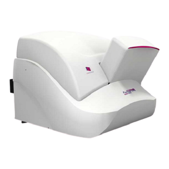
Pannoramic 250 1.15 User’s Guide 1 Product Description 1.1.4 Main parts of the Base Unit The following figures show the main parts of the base unit. Figure 2 – Main parts of base unit 1. Protective FL cover 2. Input and output stack for magazines 3. -
Page 16: Pannoramic 250 System
Pannoramic 250 1.15 User’s Guide 1 Product Description 1.2.1 Pannoramic 250 system The following figure shows the main parts of the Pannoramic 250 system. Figure 3 – Pannoramic 250 system overview 1. Pannoramic 250 base unit 2. Monitor 3. Mouse 4. - Page 17 Pannoramic 250 1.15 User’s Guide 1 Product Description Cameras AxioCam MRm Rev 3 1 CCD scientific, cooled, monochrome camera for high quality, sensitive fluorescent applications. CIS VCC-F52U25CL 3 CCD camera for high-quality brightfield applications allowing fast scanning. pco.edge Equipped with a high-quality sCMOS image sensor for fluorescent applications allowing fast scanning and an outstanding low read out noise.
- Page 18 Figure 4 – Motorized camera changer You can fit two cameras into the Pannoramic 250 on the first adapter (1) (fluorescent position) and the second adapter (2) (brightfield position) at the same time. They are set and switched by the software automatically, without any human assistance.
- Page 19 Objectives Figure 5 – Objective changer You can select two different objectives to be equipped with the Pannoramic 250, the first objective (1) and the second objective (2). 20x/NA 0.80 and 40x/NA 0.95 objectives can be used (the 40x objective cannot be used in Brightfield mode, but only in Fluorescent).
- Page 20 Base Unit options Pannoramic 250 Base Unit • Pannoramic 250 Scan Option – base unit equipped with CIS VCC-F52U25CL camera for • Brightfield scanning (no fluorescent accessories included) Pannoramic 250 Basic Fluorescence Option – base unit completely equipped with CIS VCC- •...
-
Page 21: Control Software
Pannoramic 250 1.15 User’s Guide 1 Product Description Fluorescent Options for Pannoramic 250 Fluorescent unit (internal part) HXP 120 illumination unit (can be used with AxioCam MRm Rev3 only) Lumencor Spectra 7 Light Engine illumination unit (can be used with pco.edge camera only) - Page 22 Pannoramic 250 1.15 User’s Guide 1 Product Description Pannoramic Viewer software (fully functional) • Optional: CaseCenter • Pannoramic Viewer TMA module • 3D Reconstruction module • HistoQuant, NuclearQuant, MembraneQuant, FISHQuant, and DensitoQuant modules • ImmunoScreener module • E-School Encoder •...
-
Page 23: Installation
Pannoramic 250 1.15 User’s Guide 2 Installation 2 Installation Warning! The installation of Pannoramic 250 must be carried out by trained professionals! In any other case the warranty will be automatically voided. Supplier/Distributor is not liable for any damages caused by an installation that is not carried out by a professional person. -
Page 24: Connectors And Cables
Power supply cable (between 230V/110V and monitor) • Power supply cable (between 230V/110V and control computer) • Power supply cable (between 230V/110V and Pannoramic 250 main unit) • Optical cable (between HXP 120 fluorescent illuminator and scanner) • Trigger cable (between AxioCam and HXP 120 fluorescent illuminator) •... -
Page 25: Mounting The Lumencor Spectra Unit
(see section 1.1.3 Main parts of the Base Unit). 2. Open protective cover (see section 5.3.1 Opening the protective cover). 3. Find the mounting hole (1) at the back side of the Pannoramic 250 unit and rotate the Lumencor unit (2) upside down. - Page 26 6. Secure the locking lever by moving it to the left (see Figure 10 – Step 2). If the lever stucks at around the center position, apply a bit more pressure to the Lumencor unit. Figure 10 – Mounting the Lumencor unit 7. Close the protective cover of the Pannoramic 250. March 13, 2012 – Rev. 1 3DHISTECH Ltd.
-
Page 27: Operating Slides And Magazines
Pannoramic 250 1.15 User’s Guide 3 Operating Slides and Magazines 3 Operating Slides and Magazines 3.1 Preparing Slides and Magazines This section demonstrates how to prepare slides and magazines. You can use all slides and cover slips that meet the following specifications:... -
Page 28: Affixing Barcode Stickers To Slides
Pannoramic 250 1.15 User’s Guide 3 Operating Slides and Magazines Caution! Ensure that no part of the mounted coverslip protrudes from the edges of the slide. Use slides only with completely dried embedding medium. If not so, the coverslip can be shifted that makes slide loading less reliable. Not completely dried embedding might also influence the operation of objectives and other device parts. -
Page 29: Inserting And Removing Slides
Pannoramic 250 1.15 User’s Guide 3 Operating Slides and Magazines Note: Ensure that a marginal space of 1-2 mm remains on all sides between the sticker and the label area outer limits. It is vital for barcode identification. Caution! Do not let barcode sticker protrude from slide edges, or stick on the coverslip surface (3). -
Page 30: Insert And Remove Magazines
Pannoramic 250 1.15 User’s Guide 3 Operating Slides and Magazines Only original 3DHISTECH P250 magazines are allowed for use with Pannoramic 250! The magazines can contain a maximum of 25 slides. Push slide (1) into the magazine (3) with its barcode end (2) first. The symbols on the side of •... - Page 31 Pannoramic 250 1.15 User’s Guide 3 Operating Slides and Magazines Pannoramic 250 has two pairs of guide rails (5) to manage the loading and unloading of magazines. Warning! Do not omit to close the protective cover! It must be closed while the...
- Page 32 Pannoramic 250 1.15 User’s Guide 3 Operating Slides and Magazines 3. Slide down the magazine on the input guide rails until it rests on the gear wheels (6) or magazines. Figure 14 – Gear wheels Caution! Make sure that the magazines are not misplaced, because it can cause serious damages in the feeding mechanism.
-
Page 33: Opening/Closing The Fl Protective Cover
Pannoramic 250 1.15 User’s Guide 3 Operating Slides and Magazines Caution! Do not place magazines into the output stack (4) or remove magazines with already digitized slides from there during the digitization process. Only remove magazines from the output stack when you have finished digitization of all slides. -
Page 34: Software Description
1. To start the program, double-click on the program icon on the desktop or start it from Start Menu\ All Programs \ 3DHISTECH \ Pannoramic Scanner 2. During start-up, all motors, the preview camera and the scan camera are initialized. After successful initialization, the program displays a Mode selection window. -
Page 35: Exiting The Software
Pannoramic 250 1.15 User’s Guide 4 Software Description The camera changer changes the cameras according to the settings in the Microscope Settings options depending on the selected scan modes. It changes to the camera defined for Brightfield scanning if Brightfield scan mode is selected, whereas it changes to the camera defined for fluorescent scanning if Fluorescent scan mode is selected. -
Page 36: Barcode Settings
Pannoramic 250 1.15 User’s Guide 4 Software Description 4.2.1 Barcode Settings Figure 19 – Barcode settings Before starting the control software, you have to set the barcode settings here. By predefining the barcode type, foreground color (black or white – the color of the barcode), and other settings, you enable the Read Barcode option when using the control software. - Page 37 Pannoramic 250 1.15 User’s Guide 4 Software Description Functions To move the lowest magazine in the input stack to the loading position click • To move the magazine into the output stack, click • To move a selected slide from its magazine to the specimen holder either enter its position •...
- Page 38 Pannoramic 250 1.15 User’s Guide 4 Software Description 2D Barcode Types You can select the following 2D barcode types: Data Matrix • PDF417 • MicroPDF417 • Maxicode • QR code • 1D barcodes with check digit (CDV) You can select the following 1D barcodes with check digit (CDV): Code 39 •...
-
Page 39: Image Compensation
Pannoramic 250 1.15 User’s Guide 4 Software Description 4.2.2 Image Compensation You can create a new compensation image when there are compensation errors (deriving from the slide, illumination, staining or embedding medium irregularities) from an empty slide by setting these options. - Page 40 Pannoramic 250 1.15 User’s Guide 4 Software Description Camera Selection This field displays the active camera. Currently, there is only one active camera for Brightfield mode and one active camera for Fluorescent mode. Objective Selection To select the objectives to be used for creating a new compensation image, select the checkbox(es).
- Page 41 Pannoramic 250 1.15 User’s Guide 4 Software Description Figure 21 – Image compensation March 13, 2012 – Rev. 1 3DHISTECH Ltd. 41(135)
- Page 42 Pannoramic 250 1.15 User’s Guide 4 Software Description Note: If you cannot create appropriate compensation images, maybe the compensation slide needs to be replaced. To order new Fluorescent Compensation Slides, contact 3DHISTECH Service Support. Camera Selection This field displays the active camera.
- Page 43 Pannoramic 250 1.15 User’s Guide 4 Software Description Preview Settings Set the threshold on the preview image by using the compensation slide. The crosshair on the slide must be focused, and set the Current threshold value to mark the specks together with the crosshair red, or use the selection box by selecting Use Selection Box.
-
Page 44: Microscope Settings
Pannoramic 250 1.15 User’s Guide 4 Software Description 4.2.3 Microscope Settings You can define for the software which filters occupy which turret positions. By moving the mouse over the buttons, the software displays information about the setting you are interested in. - Page 45 If you have transported the product, or changed the camera, there is a possibility, that the camera does not display the images properly. If you experience such problems, contact 3DHISTECH service support. Do not modify these settings yourself. March 13, 2012 – Rev. 1 3DHISTECH Ltd.
- Page 46 Pannoramic 250 1.15 User’s Guide 4 Software Description Figure 24 – Camera Rotation tab panel March 13, 2012 – Rev. 1 3DHISTECH Ltd. 46(135)
- Page 47 Pannoramic 250 1.15 User’s Guide 4 Software Description Z Difference This function is available only for fluorescence settings; it enables you to set the basic focus differences between the filters. This facilitates more precise focusing during scanning. Figure 25 – Z Difference tab panel March 13, 2012 –...
- Page 48 Pannoramic 250 1.15 User’s Guide 4 Software Description Service Figure 26 – Service tab panel This tab panel contains control and maintenance functions. Emergency Manual Slide Removal Position The specimen holder will be moved to a position where the slide can be removed manually after opening the cover (see section 5.3.1 Opening the protective cover).
-
Page 49: External Application Call Settings
Pannoramic 250 1.15 User’s Guide 4 Software Description 4.2.4 External Application Call Settings Figure 27 – External Application Settings These settings open any external application (.exe or .bat) as defined. For example, it might start the Viewer software after finishing scanning, or stop the computer after scanning is finished. -
Page 50: Using Brightfield Manual Mode
Pannoramic 250 1.15 User’s Guide 4 Software Description Run defines the window mode that the external application will start in. The following window modes can be set: Normal window • Minimized • Maximized • You can test whether the Error Occurred Call settings work by clicking . -
Page 51: Routine Work Tab Panel
Pannoramic 250 1.15 User’s Guide 4 Software Description 1. Tab panel with scanner functions and setting 2. Scan camera live image display area 3. Preview image recorded by the preview camera 4. Preview image editor toolbar 5. Information area about the digitization progress 4.3.1 Routine work tab panel... - Page 52 Pannoramic 250 1.15 User’s Guide 4 Software Description To enter the slide name To enter the slide name manually, type it into the Slide Name field. • You can also use the barcode as a slide name if a compatible barcode sticker is affixed on •...
-
Page 53: Scan Options Window
Pannoramic 250 1.15 User’s Guide 4 Software Description 4.3.2 Scan Options window Figure 30 – Scan options window These settings will determine the resulting quality and storage location of the virtual slide. You can choose the following image formats in the Image Encoding field: JPEG –... -
Page 54: Preview Tab Panel
Pannoramic 250 1.15 User’s Guide 4 Software Description Scan Settings Interpolated focus distance – the distance of focal points can be set to create a focus map, • based on which the software calculates interpolated focus values (one step in distance means one FOV). - Page 55 Pannoramic 250 1.15 User’s Guide 4 Software Description Figure 31 – Preview tab panel Use threshold Brightfield preview – a normal type of illumination in the microscope for scanning the slide. • Darkfield preview – the preview image is created with transmitted Darkfield illumination.
- Page 56 Pannoramic 250 1.15 User’s Guide 4 Software Description Scan specimen with user set threshold – This sets the sensitivity of the specimen • detection. To set the desired threshold value manually, change the setting in the Specimen threshold level selection box in the range of 0-255. The default value is Smaller values result in a more sensitive scanning, meaning that more areas will be digitized, however, this may also include specks or other imperfections of the slide.
- Page 57 Pannoramic 250 1.15 User’s Guide 4 Software Description Figure 33 – Preview image with and without coverslip edge Caution! It requires lots of time and memory (since it cannot find focus neither on the edges, nor on specks) to digitize coverslip edges. Select Remove coverslip function to eliminate those areas.
-
Page 58: Preview Area Scanned By Preview Camera
Pannoramic 250 1.15 User’s Guide 4 Software Description To save a new mask, click Save. It will display a drop-down menu. Select whether to save preview mask or TMA grid. To load a mask, click Load. It will display a drop-down menu. Select whether to load preview mask or TMA grid. - Page 59 Pannoramic 250 1.15 User’s Guide 4 Software Description Areas that will be scanned These areas are digitized on the basis of user settings (for example, Fill holes in scan area) and not detected by the selected threshold value. Detected sample areas that will be scanned These areas are digitized.
- Page 60 Pannoramic 250 1.15 User’s Guide 4 Software Description You can select the area to be scanned with the different tools on the toolbar: Square tool • Ellipse tool • Polygon tool: you can finish the selection process with the polygon tool by •...
- Page 61 Pannoramic 250 1.15 User’s Guide 4 Software Description Figure 37 – Not scanned selection TMA tool TMA tool is used for selecting TMA spots on TMA slides. You can set the selection settings on the following four tabs: Select tab panel Figure 38 –...
- Page 62 Pannoramic 250 1.15 User’s Guide 4 Software Description Block tab panel Figure 39 – TMA tool: Block Set the TMA block type in this tab panel. 1. Select the shape of the TMA spots (Rectangle spots or Circle spots). 2. Enter the number of rows and columns in the Rows and Columns fields or select the appropriate values with the arrows.
- Page 63 Pannoramic 250 1.15 User’s Guide 4 Software Description Move tab panel The Move tab panel allows the rotation and moving of the TMA selection spots that are displayed on the preview image. To move the spots enter the pixel value in the Move field or use the arrows.
-
Page 64: Focus Tab Panel
Pannoramic 250 1.15 User’s Guide 4 Software Description Label area To rotate the label area by 180°, select the Rotate image by 180 degree checkbox. Figure 42 – Label area 4.3.5 Focus tab panel Figure 43 – Focus tab panel March 13, 2012 –... - Page 65 Pannoramic 250 1.15 User’s Guide 4 Software Description Live Click to display a live image of the current specimen in the Live image display field. This option has no effect on a running digitization process where no live image is displayed.
-
Page 66: Service Tab Panel
Pannoramic 250 1.15 User’s Guide 4 Software Description With the Z-stack method separate layers are created and stored, and can be opened with • Pannoramic Viewer. The Z-stack slide contains the extended focus layer. Both for Extended focus and Z-Stack scanning methods, you can determine the desired number of focus levels with the Focus levels selection box. - Page 67 Pannoramic 250 1.15 User’s Guide 4 Software Description Figure 46 – Display field and toolbar for live images Toolbar for live images The toolbar is only available for the displayed live image, but not available for camera images during digitization.
-
Page 68: Start Scan
Pannoramic 250 1.15 User’s Guide 4 Software Description – Displays or hides the vertical and horizontal scale bars • – Displays the magnifier window • – Activates red marking on overexposed pixels • – Recalculates exposure time (useful if too many overexposed pixels were •... -
Page 69: Using Brightfield Automatic Mode
Pannoramic 250 1.15 User’s Guide 4 Software Description 4.4 Using Brightfield Automatic Mode Compared to Manual mode, it has less options in some dialogs, but it has an additional Barcodes tab. 4.4.1 Routine work tab panel Figure 47 – Routine work tab panel The Routine work tab panel provides basic digitization functions. - Page 70 Pannoramic 250 1.15 User’s Guide 4 Software Description To administer profiles, use the Scan Profiles field. The current profile name is displayed at the bottom left corner of the screen. • To save the current profile, click Save. • To select an existing profile from the selection menu, click Load.
-
Page 71: Barcodes Tab Panel
Pannoramic 250 1.15 User’s Guide 4 Software Description 4.4.2 Barcodes tab panel Figure 48 – Barcodes tab panel March 13, 2012 – Rev. 1 3DHISTECH Ltd. 71(135) - Page 72 Pannoramic 250 1.15 User’s Guide 4 Software Description On this tab panel you can set identification features and profiles for slides as follows: Features on the panel 1. Apply one profile to all slides. One profile is used for all slides in a batch.
- Page 73 Pannoramic 250 1.15 User’s Guide 4 Software Description Note: You can separate the character groups with any character you choose, it will not be read by the software. Example for barcode usage Barcode: Folder_Vir_123_prof_n • Folder is the folder for saving •...
- Page 74 Pannoramic 250 1.15 User’s Guide 4 Software Description The number before M represents the magazine number. The number after M represents the slide position. In this example, the name indicates a slide in magazine 1, position 10. You can also define names for the slides in the table below, by entering names into the column Names / Barcodes.
-
Page 75: Preview Tab Panel
Pannoramic 250 1.15 User’s Guide 4 Software Description 4.4.3 Preview tab panel Figure 49 – Preview tab panel The Preview tab panel offers options for threshold setting and selection of the area to be scanned. The options in Automatic mode are the same as described in Manual mode. -
Page 76: Focus Tab Panel
Pannoramic 250 1.15 User’s Guide 4 Software Description 4.4.4 Focus tab panel Figure 50 – Focus tab panel Focus You can define focus limits by selecting Limit focus range. You can set the upper and lower limits by selecting the desired value in the selection boxes. This is useful if focusing was not targeted on the specimen, but on a spot on the coverslip. -
Page 77: Service Tab Panel
Pannoramic 250 1.15 User’s Guide 4 Software Description With the Z-stack method separate layers are created and stored, and can be opened with • Pannoramic Viewer. The Z-stack slide contains the extended focus layer. Both for Extended focus and Z-Stack scanning methods, you can determine the desired •... -
Page 78: Start Scan
Pannoramic 250 1.15 User’s Guide 4 Software Description 4.4.6 Start Scan To start digitization process, click after checking settings in the Barcodes tab panel. Caution! Before starting digitization process ensure that you have enough free space on the destination drive. You can check the available free disk space in the last line (Available disk space) of the information area of Current Slide Scan Progress (see Figure 53). -
Page 79: Using Fluorescent Manual Mode
Pannoramic 250 1.15 User’s Guide 4 Software Description 4.5 Using Fluorescent Manual Mode 4.5.1 Routine work tab panel Figure 54 – Routine work tab panel March 13, 2012 – Rev. 1 3DHISTECH Ltd. 79(135) - Page 80 Pannoramic 250 1.15 User’s Guide 4 Software Description The Routine work tab panel provides the following basic digitization functions: To insert and remove slides To move the lowest magazine in the input stack to the loading position click • To move the magazine into the output stack, click •...
- Page 81 Pannoramic 250 1.15 User’s Guide 4 Software Description To enter the slide name You can enter the slide name manually by typing it into the Slide Name field. • You can also use the barcode as a slide name if a compatible barcode sticker is affixed on •...
- Page 82 Pannoramic 250 1.15 User’s Guide 4 Software Description Those filters are displayed automatically that you have previously defined in the Options / Microscope Settings at the mode selection screen. For more information on predefining filters, see section 4.2.3 Microscope Settings / Base Settings.
- Page 83 Pannoramic 250 1.15 User’s Guide 4 Software Description Digital Gain Note: This is camera-dependent, when working with AxioCam MRm Rev 3 camera the Index value ranges from 0 to 4, and in case using the pco.edge camera, the value ranges from 0 to 6.
-
Page 84: Scan Options
Pannoramic 250 1.15 User’s Guide 4 Software Description 4.5.2 Scan Options Figure 57 – Scan options tab panel March 13, 2012 – Rev. 1 3DHISTECH Ltd. 84(135) - Page 85 Pannoramic 250 1.15 User’s Guide 4 Software Description These settings determine the resulting quality and storage location of the virtual slide. Image Encoding You can set the image format parameters within this group. JPEG – The quality can be adjusted with the JPEG quality factor slider. Greater •...
- Page 86 Pannoramic 250 1.15 User’s Guide 4 Software Description Caution! If the specimen area is barely visible, it is possible that the software will analyze that area as an empty one. Do not use extended focus on empty field-of-views – If selected, the •...
- Page 87 Pannoramic 250 1.15 User’s Guide 4 Software Description Multi Filter Change Mode This is for a multi-channel digitization. To optimize speed, filter change should take place after the digitization of the slide with one channel. Filters should be changed for each field of view if very precise colocalization is required.
-
Page 88: Preview Tab Panel
Pannoramic 250 1.15 User’s Guide 4 Software Description 4.5.3 Preview tab panel The Preview tab panel offers options for threshold setting and selection of the area to be scanned. Figure 58 – Preview tab panel Use threshold Brightfield preview – a normal type of illumination in the microscope for scanning the slide. - Page 89 Pannoramic 250 1.15 User’s Guide 4 Software Description Figure 59 – Brightfield and Darkfield preview images of the same slide Scan specimen with auto threshold – This automatically detects the specimen in • the preview image. Scan specimen with user set threshold – This sets the sensitivity of the specimen •...
- Page 90 Pannoramic 250 1.15 User’s Guide 4 Software Description Note: This step is recommended when using FL mode, as the application is less capable of finding the specimen based on the specimen threshold level. Figure 60 – Scan everything within marked area option is selected / not selected General threshold options Remove coverslip –...
-
Page 91: Hardware Tab Panel
Pannoramic 250 1.15 User’s Guide 4 Software Description 4.5.4 Hardware tab panel Figure 61 – Hardware tab panel (selected mode: User controlled) Live Click to display a live image of the current specimen in the Live image display field. March 13, 2012 – Rev. 1 3DHISTECH Ltd. - Page 92 Pannoramic 250 1.15 User’s Guide 4 Software Description This option has no effect on a running digitization process where no live image is displayed. To display a live image during scanning, select Show images during scanning on the Service tab panel.
- Page 93 Pannoramic 250 1.15 User’s Guide 4 Software Description Focus To define focus limits, select Limiting the range checkbox. Set the upper and lower limits by selecting the desired value in the selection boxes. This is useful if Auto Focus does not find the focus on the specimen, but on the coverslip.
-
Page 94: Service Tab Panel
Pannoramic 250 1.15 User’s Guide 4 Software Description If you select the Interpolated focus option, the coarse focus level is calculated from three different focus points of the specimen. Carry out a manual focusing sequence in the preview image on those three points. - Page 95 Pannoramic 250 1.15 User’s Guide 4 Software Description Slide Removed Manually Click this button to notify the software that you have removed the slide manually. Show images during scanning If you select this option, you will be able to see the currently scanned image field during scanning in the live image display field.
-
Page 96: Using Fluorescent Automatic Mode
Pannoramic 250 1.15 User’s Guide 4 Software Description 4.6 Using Fluorescent Automatic Mode 4.6.1 Routine work tab panel Figure 63 – Routine work tab panel The Routine work tab panel provides some basic digitization functions. March 13, 2012 – Rev. 1 3DHISTECH Ltd. - Page 97 Pannoramic 250 1.15 User’s Guide 4 Software Description To insert and remove slides In Automatic mode a preloaded magazine has to be placed into the main unit. This magazine • is the first one, irrespectively of the total number of magazines (1-10) to be loaded.
- Page 98 Pannoramic 250 1.15 User’s Guide 4 Software Description Filter Settings Focus channel – Choose a filter that you want to focus with. It is recommended to choose a • filter that is related to the staining that stained the most of the specimen, or where the exposition time is low.
- Page 99 Pannoramic 250 1.15 User’s Guide 4 Software Description Figure 64 – Filter properties window Filter name The name of the filter is displayed here. Exposure Settings Exposure time – You can set the fix exposition time here. By selecting the...
- Page 100 Pannoramic 250 1.15 User’s Guide 4 Software Description Digital Gain Note: This function is camera-dependent, works only with AxioCam MRm Rev 3 camera (Index value ranges from 0 to 4) and pco.edge (Index values: 0-6). You can enter the Index value by entering it in the box or by selecting the value with the arrow buttons.
-
Page 101: Barcodes Tab Panel
Pannoramic 250 1.15 User’s Guide 4 Software Description 4.6.2 Barcodes tab panel Figure 66 – Barcodes tab panel On this tab panel, you can set identification features to the various slides and for assigning profiles. March 13, 2012 – Rev. 1 3DHISTECH Ltd. - Page 102 Pannoramic 250 1.15 User’s Guide 4 Software Description Modes on the tab panel Apply one profile to all slides • One profile is used for all slides in a batch. • Current Profile is the profile that was loaded in Routine work / Scan Profiles.
- Page 103 Pannoramic 250 1.15 User’s Guide 4 Software Description Note: You can separate the character groups with any character you choose, it will not be read by the software. Example for barcode usage Barcode: Folder_Vir_123_prof_n • Folder is the folder for saving •...
- Page 104 Pannoramic 250 1.15 User’s Guide 4 Software Description You can also define names for the slides in the table, by entering names into the column Names / Barcodes. You can also define profiles in the selection boxes in column Profiles if you intend to use different profiles for slides.
-
Page 105: Preview Tab Panel
Pannoramic 250 1.15 User’s Guide 4 Software Description 4.6.3 Preview tab panel Figure 67 – Preview tab panel The Preview tab panel offers options for threshold setting and selection of the area to be scanned. The options in Automatic mode are the same as described in Manual mode. -
Page 106: Focus Tab Panel
Pannoramic 250 1.15 User’s Guide 4 Software Description 4.6.4 Focus tab panel Figure 68 – Focus tab panel Focus You can define focus limits by selecting Limit focus range checkbox. You can set the upper and lower limits by selecting the desired value in the selection boxes. -
Page 107: Scan To Server
4.7 Scan to Server If you want to scan directly to a server, first you have to install the ScanToServer which is an embedded application that can be run under the Pannoramic 250 scanner software. Follow these steps to install the ScanToServer application: 1. - Page 108 Pannoramic 250 1.15 User’s Guide 4 Software Description 3. Click Finish to finalize the installation process of the ScanToServer application. To setup a connection with a designated server, follow the steps below: 1. Click Scan Options on the Routine Work tab panel.
- Page 109 Pannoramic 250 1.15 User’s Guide 4 Software Description 2. Select the Scan to CaseCenter option in the Scan Option window, then click Connect. Figure 71 – Scan to CaseCenter option 3. Type in or select the server address from the Connect to: drop-down menu, and give the User name and password.
- Page 110 Pannoramic 250 1.15 User’s Guide 4 Software Description Slide settings in the CaseCenter window 1. In the Routine work tab panel, click the button. 2. The CaseCenter window is displayed. Slide data is displayed in a form. If in Manual Mode, only the data of the actually loaded •...
- Page 111 Pannoramic 250 1.15 User’s Guide 4 Software Description Give the number of the starting (First slide) and the final slide (Last slide) to be • scanned in the appropriate field. For example, if you want to scan slides to server from 3-14, type: First slide: 3;...
- Page 112 Pannoramic 250 1.15 User’s Guide 4 Software Description Select a folder where the slide will be scanned to. After clicking the Folder drop- • down list, a path will be displayed in which the destination folder can be selected. Figure 76 – Folder selection Fill in the Case and Block fields in case you do not use masks, or select an item from •...
-
Page 113: Using Profiles
Pannoramic 250 1.15 User’s Guide 4 Software Description 4.8 Using Profiles Note: Saved profile settings cannot be transferred to and used on another control computer. If you want to scan a group of slides, it is advised to save your settings previously in a profile and continue scanning in Automatic mode. - Page 114 Pannoramic 250 1.15 User’s Guide 4 Software Description Use saved scan area • Use selection box (ON/OFF) • Fluorescent settings Filter position(s) • Selected focus channel • Selected stitching channel • Use of skip empty field-of-views (ON/OFF) • Do not use extended focus on empty field-of-views (ON/OFF) •...
-
Page 115: Troubleshooting And Maintenance
Pannoramic 250 1.15 User’s Guide 5 Troubleshooting and Maintenance 5 Troubleshooting and Maintenance 5.1 Safety Information Check cables, plugs and connections before operation, and if defective or cannot be replaced, contact 3DHISTECH Service for support. Check whether the device is compatible with your local line voltage. It can operate at line voltages 100V to 240V and 50/60 Hz. -
Page 116: Cleaning The Device
Pannoramic 250 1.15 User’s Guide 5 Troubleshooting and Maintenance When the HXP 120 illuminator is switched on: Never look directly into the fiber-optic cable. • Never remove the fiber-optic cable from the device. • Never connect the fiber-optic cable to the device. -
Page 117: Troubleshooting
6. Reconnect power supply cable of the base unit and the control computer to line power supply. 7. Switch on the power supply of the Pannoramic 250 (see section 1.1.4 Main parts of the Base Unit). 8. Switch on the control computer. - Page 118 Warning! Do not modify the camera driver settings, as the default settings adjusted by 3DHISTECH, give the most accurate images. Virtual slides show poor stitching in Pannoramic Viewer Scan camera is not properly adjusted (for example, due to loose fixture) •...
-
Page 119: Fluorescent Applications (Optional)
Pannoramic 250 1.15 User’s Guide 5 Troubleshooting and Maintenance Focus range setting is incorrect • Change focus range setting. • All individual images show a shading effect Algorithm failed to find empty image fields • Capture a reference image with a blank slide (see section 4.3.2 Scan Options). -
Page 120: Maintenance
To perform maintenance work and when slide or magazine jamming occurs, the protective cover(s) of the Pannoramic 250 need to be opened in order to eliminate the problem. Before opening the cover, exit the control software, switch off the main power supply and disconnect the power cables (see section 1.1.4 Main parts of the Base Unit). -
Page 121: Replacing Fuses Of The Main Power Switch
Pannoramic 250 1.15 User’s Guide 5 Troubleshooting and Maintenance 5.3.2 Replacing fuses of the main power switch 1. Switch off the main power supply and disconnect the power cable (see section 1.1.4 Main parts of the Base Unit). 2. The fuse compartment is located next to the main power supply switch at the back side of the Pannoramic 250. -
Page 122: Replacing Lamp Module (For Fluorescent Option)
Pannoramic 250 1.15 User’s Guide 5 Troubleshooting and Maintenance 5.3.3 Replacing Lamp Module (for Fluorescent Option) NOTE: This section recites some extracts from the HXP 120 operating manual. For detailed information, especially instructions regarding safety, consult that manual. Also, no alignment is required for the lamp module. - Page 123 Pannoramic 250 1.15 User’s Guide 5 Troubleshooting and Maintenance 4. Loosen pressure bolt with the lever (1) and by keeping the lever pressed, remove lamp module (2) (see Figure 83). Figure 83 – Removing the lamp module 5. Carefully retrieve the new lamp module from its transporting container. Hold the lamp module only by its ceramic part.
-
Page 124: Removing A Slide
Pannoramic 250 1.15 User’s Guide 5 Troubleshooting and Maintenance 11. Connect power plug. 12. Set hour meter (time counter) to zero. 5.3.4 Removing a slide If a slide got jammed or has suffered breakage during the process of digitization, stop the process and, if possible, move the slide holder to a position where the slide can be easily removed by clicking the Emergency Manual Slide Removal Position button (see section 4.3.6 Service tab panel). - Page 125 7. Turn down the slide loader back into the original position and pull it inwardly (to the Pannoramic 250), until the guiding pin connects with the motor block groove again. 8. Press the slide loader down to mechanical stop position, in which the locking lever must engage (1).
-
Page 126: Installing And Removing The Filter Module (Fluorescent Option)
Pannoramic 250 1.15 User’s Guide 5 Troubleshooting and Maintenance 5.3.5 Installing and Removing the Filter Module (Fluorescent Option) Figure 87 – Installing and removing the filter module 1. Switch the HXP 120 illuminator off. Warning! Crush hazard! Stop the running digitization process before you proceed with filter module installation or removal. -
Page 127: Removing A Magazine From The Transporting System
Pannoramic 250 1.15 User’s Guide 5 Troubleshooting and Maintenance Warning! Avoid touching the surface of the filters, and store the modules in their own boxes when not used. 6. Press the filter module down, until it safely connects to the bottom spring-loaded clamps (2) of the filter wheel. - Page 128 Note: Any manipulation performed on a mechanical component (for example, transporting system) by the user must be followed by a complete Pannoramic 250 initialization routine (software restart). March 13, 2012 – Rev. 1 3DHISTECH Ltd. 128(135)
-
Page 129: Transporting
Pannoramic 250 1.15 User’s Guide 5 Troubleshooting and Maintenance 5.3.7 Transporting The following procedure shows how to transport Pannoramic 250. Figure 89 – Transporting handles Caution! Do not use the protective cover (2) to raise, shift or transport Pannoramic 250! March 13, 2012 –... - Page 130 2. Pull carrying handles out (1) until mechanical stop position (A). 3. Turn carrying handles by 90° (B) towards the base unit to secure them. 4. Now you can transport Pannoramic 250 with the help of another person. 5. After finishing transportation, push carrying handles back into normal position (C).
-
Page 131: Technical Data
Pannoramic 250 1.15 User’s Guide 6 Technical Data 6 Technical Data Dimensions (width × depth × height) Base unit approx. 68×95×55 cm Base unit without fluorescence option approx. 68×69×55 cm Weight Base unit approx. 46 kg Base unit with fluorescent option approx. - Page 132 Pannoramic 250 1.15 User’s Guide 6 Technical Data Operating data Intended site closed room facilities Electrical protection class Internal protection degree IP 20 Electrical safety in compliance with DIN EN 61010-1:2001, DIN EN 61010-2- 101:2002 (IEC 61010-1:2001, IEC 61010-2-101:2002) Over-voltage category...
- Page 133 Pannoramic 250 1.15 User’s Guide 6 Technical Data EAN8 (Numeric encoding) • EAN13 (Numeric encoding) • UPC-A (Numeric encoding) • DataMatrix (Numeric encoding, Alpha encoding, AlphanumericPunc encoding, • AlphaNumeric encoding, ASCII encoding, IS08 encoding) Maxicode (Encoding mode 2, 3, 4, 5, 6) •...
- Page 134 Pannoramic 250 1.15 User’s Guide 6 Technical Data CIS VCC-F52U25CL camera 1/1.8” PS IT CCD Pixel size 4.40×4.40 µm Camera resolution 1624(H) × 1224(V) pixel Camera max. speed up to 30 frames per second Bit-depth 10 bit Pixel resolution with 20x objective and 1x C-mount adapter 0.22µm...
-
Page 135: Index
Lumencor..............2, 12, 16, 20, 21, 24, 25, 26, 93, 118, 122, 135 Marker..........................56, 59, 90, 116 Pannoramic 250..2, 8, 9, 10, 12, 14, 16, 18, 19, 20, 21, 23, 24, 25, 26, 30, 31, 108, 120, 123, 124, 128, 131, 132, 133 Pannoramic Viewer....................22, 66, 77, 120, 121...
Need help?
Do you have a question about the Pannoramic 250 and is the answer not in the manual?
Questions and answers