
Related Manuals for CoolLED pE-300 Series


Summary of Contents for CoolLED pE-300 Series
- Page 1 User Manual pE-300 Series White Light Fluorescence Illumination System DOC-005 Iss 15...
-
Page 2: Table Of Contents
) ..................27 Settings / Additional Information ................. 29 Routine Care and Maintenance ..................32 Fitting the pE-300 Series Illumination System to a different microscope ....33 Product specifications ....................34 Product options and order codes .................. 35 Warranty and Repairs ....................35 Compliance and Environmental .................. -
Page 3: Introduction
CoolLED’s pE-300 Series illumination systems are designed to offer broad spectrum LED illumination for general use in fluorescence microscopy applications. The pE-300 Series can be fitted directly to the microscope as a better and safer alternative to high pressure mercury or metal halide illuminators. -
Page 4: Safety Precautions
Safety Precautions While LEDs are a much safer illumination system than the mercury and metal halide lamps that they replace in microscopy applications, precautions should still be taken with this product. When operating or maintaining this product, please observe the following safety precautions at all times. - Page 5 2.6. Any electronic equipment connected to this product must comply with the requirements of EN/IEC 60950. 2.7. To clean the exterior of the Light Source, use a slightly dampened cloth with a simple water/detergent solution only. Avoid the optical surfaces and lenses.
-
Page 6: Pe-300 Series Variants
Series variants All versions in the pE-300 Series offer intense, broad spectrum LED illumination. With spectral coverage from the UV (DAPI excitation) to the Red region (Cy5 excitation) they are suitable for imaging most common fluorescent stains. Light sources are available for either direct attachment to the microscope or via liquid light guide delivery. - Page 7 The pE-300 allows the greatest level of control in the pE-300 Series. The Illumination System allows control of the three channels using the Manual Control Pod, USB or by the four TTL inputs (one TTL input for each channel, as well as a global TTL).
-
Page 8: Getting Started - System Components
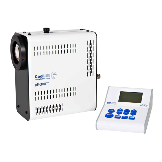
Getting Started – System Components A typical CoolLED pE-300 Series Illumination System is supplied with the following components: 1. LED Light Source. 2. Manual Control Pod. 3. Microscope adaptor for specific microscope model (Direct fit only). 4. DC Power Supply Type GST120A12-R7B. -
Page 9: Installation And Setup
DC power supply is the one supplied with the product. Using non- CoolLED power supplies may damage the Light Source and will invalidate the warranty. At this stage do not connect the mains power lead to the DC power supply. - Page 10 5.4. Attach the LED Light Source to the epi-fluorescence port on your microscope. Your pE-300 Series Light Source will have been supplied with a compatible fitting for the microscope you specified at order (if direct fit version). Attach the Light Source ensuring that it is secure and true/flush with the microscope.
-
Page 11: Configuration Of Leds As A White Light Source
LEDs of different wavelengths have to be combined together. Using a pumped phosphor, a broader peak covering green, yellow and red emissions can also be created. In the pE-300 Series, LEDs emitting in the UV and blue regions are combined with a pumped phosphor to create a white illumination system covering all the commonly used fluorescence stains. - Page 12 6.2. white ultra The pE-300 and pE-300 have independent circuits giving the user control of the three main peaks of emissions. On the standard configuration, these are referred to as 1UV, 2B (blue) and 3GR (green, yellow, red). 6.3. white ultra There is also a variant of the pE-300 and pE-300...
-
Page 13: Operation - Manual Control
Operation - Manual Control white ultra 7.1. pE-300 & pE-300 7.1.1. Manual Control Pod Operation on/off. white ultra The pE-300 and pE-300 are easily controlled from the manual Control Pod. LEDs are switched on and off by pressing the ‘on/off’ button. 7.1.2. - Page 14 7.1.4. To switch off the LEDs, press the ‘on/off’ once again. 7.1.5. Intensity Control. The Control Pod enables the user to control the intensity of the LEDs that are exciting different stains. This helps to balance the emissions so that one stain does not dominate another.
- Page 15 7.1.7. Individual bands can be switched off (de-selected) by pressing the ‘select’ button. Light is then only generated where it is required to excite the stains in use. This has many attractive benefits with improvements in contrast, cell viability and savings in energy. Switching off UV will help to reduce damage to cells through photo- bleaching.
- Page 16 lite 7.2. pE-300 7.2.1. At start-up the Light Source will revert to the same settings that were set when it was last powered down. 7.2.2. To switch on the LEDs press the “on/off” button once. 7.2.3. To control the intensity of the light output, use the “+” and “-“buttons to increase or decrease in 1 % steps.
-
Page 17: Remote Operation - Ttl (Pe-300 White & Pe-300 Ultra )
white Remote Operation – TTL (pE-300 & ultra pE-300 white ultra The pE-300 and the pE-300 can both be controlled remotely via a TTL signal. white ultra 8.1. Global triggering (pE-300 & pE-300 8.1.1. white ultra The pE-300 and the pE-300 both have a BNC socket on the rear of the Light Source which allows global control of the Illumination System Global BNC... - Page 18 ultra 8.2. Individual channel triggering (pE-300 8.2.1. ultra In addition to the global TTL control available, the pE-300 also has three additional BNC sockets that allow individual TTL channel control of the Illumination System. Channel 1 Channel 2 Channel 3 8.2.2.
- Page 19 8.3.2. The Sequence Runner mode is accessed by a short duration press of the mode button on the Control Pod. 8.3.3. Order in triggering sequence ON/OFF state of the Illumination System. Channel intensity (0-100 %) Installed channels DOC-005 Iss 15...
- Page 20 8.3.4. Pressing the channel select button allows you to either deselect a channel or change the order that it triggers in the sequence. 8.3.5. Pressing the + & - buttons on the Control Pod will allow the light intensity of the corresponding channel to be increased or decreased.
- Page 21 8.3.6. The sequence will not begin until the ON/OFF button on the Control Pod is pressed. In this example channel 2 will pulse at 100 % intensity, channel 3 will pulse at 65 % and then channel 1will pulse at 100 %. This Sequence will continue until the ON/OFF button is pressed again to stop the sequence.
- Page 22 8.4. TTL triggering information 8.4.1. The TTL input circuit has been designed to maximise the switching speed of the LEDs to give the user precise control of the excitation light reaching the sample. This diagram shows the worst case triggering speeds when triggered at 100% intensity. There will be slight differences in speed between channels and at different intensities.
-
Page 23: Remote Operation - Usb (Pe-300 White & Pe-300 Ultra )
9.3. When you first plug your CoolLED system into your PC with the USB cable, Windows will ask for a driver file unless one has already been installed. You should point Windows to the file available from CoolLED. - Page 24 9.5. Click on the CoolLED tab near the bottom of the page and you will see the link ‘CoolLED pE Driver’. Just click on this link to download then unzip before pointing Windows to this file. 9.6. Once the CoolLED device has been successfully installed into Windows you should look at the Virtual COM ports assigned by going into Device Manager.
-
Page 25: Optical Setup
Direct fit version 10.1.1. The pE-300 Series has been designed to work on the majority of fluorescence microscopes, both new and old. As would be expected, there is some variation in the optical path and elements within every microscope. In... - Page 26 10.2.3. The pE-300 Series Illumination Systems with liquid light guide output are provided with a ‘cradle’ to ensure that they remain in a stable position during operation, as shown in the image below.
-
Page 27: Additional Filtering (Pe-300 Ultra )
10.2.4. The use of a liquid light guide will be attractive for use in electrophysiology as this allows the light source to be placed outside the Faraday cage to reduce vibration and electrical noise close up to the samples. The pE- Universal Collimator is available for these applications. - Page 28 11.2. The excitation filter holder slides accept a standard 25 mm diameter filter and is secured in place with a ball ended grub screw. Excitation Grub screw filter recess 11.3. Due to the shape of the excitation filter holder slide, it can only be fitted into the corresponding channel in one orientation.
-
Page 29: Settings / Additional Information
Settings / Additional Information 12.1. Display Backlight and Contrast settings The Control Pod display settings can be adjusted to suit the lighting environment that the instrument is being operated in. To make adjustments, press and hold the ‘mode’ button for 3 seconds. white ultra 12.1.1. - Page 30 lite 12.1.2. pE-300 Use the “+” and “-“ buttons to increase and decrease the backlight intensity. To return to the main screen, either press and hold the mode button for 3 seconds again or wait 10 seconds for the screen to automatically return. DOC-005 Iss 15...
- Page 31 12.2. System Information To interrogate the product on its hardware and firmware revisions, press and hold the ‘mode’ button for 3 seconds. Once the display settings screen appears as in 9.1, release the ‘mode’ button and then give it a second short duration press.
-
Page 32: Routine Care And Maintenance
10 seconds for the screen to automatically return. Routine Care and Maintenance 13.1. The pE-300 Series Illumination System requires little or no maintenance throughout its life. There are no field serviceable parts so there is no need to remove the covers. -
Page 33: Fitting The Pe-300 Series Illumination System To A Different Microscope
14.2. There are a small number of microscopes which require additional optics or special settings internal to the pE-300 Series Light Source. Light Sources for these microscopes will be supplied with a label on the back panel, next to the serial number. -
Page 34: Product Specifications
14.4. Fit the new adaptor and tighten grub screws. 14.5. A complete list of adaptors can be found on the CoolLED website using the link: www.coolled.com/product-detail/adaptors-2/ 14.6. The simple optical setup procedure will need to be followed when fitting the pE-300 to a different microscope. -
Page 35: Product Options And Order Codes
End-of-Life Light Sources. You can help us by filling in our online contact form and providing us with your contact details and the serial number of the CoolLED Light Source that you wish to return and we will collect it free of charge. -
Page 36: Contact Details
Contact Details CoolLED Ltd 26 Focus Way Andover Hants SP10 5NY Phone +44 (0)1264 323040 (Worldwide) 1-800-877-0128 (USA + Canada) Email info@coolled.com Online www.coolled.com DOC-005 Iss 15... - Page 37 MB (400 nm LED) SB (365 nm LED) Figure 1: The CoolLED pE-300 Series Illumination Systems include three LEDs: UV-Violet (for fluorophores such as DAPI, Hoechst and Calcofluor White), Blue (for fluorophores such as GFP, FITC, Auramine) and GYR (for fluorophores such as Cy3, TRITC, TxRed, mCherry and Cy5).
- Page 38 Fast and controllable: instant on/off and high temporal resolution with TTL or software control. Irradiance finely controlled to balance brightness with phototoxicity and photobleaching Sustainability: mercury-free, low energy consumption and long lifetime Consumable-free: no lamps or liquid light guide to replace Increasing image contrast The ability to control three channels independently increases the practical uses of white...
- Page 39 Figure 2: Capturing fast events with an LED Illumination System and Pinkel filter setup. Thanks to individual LED channel switching and inline excitation filters, the CoolLED pE- ultra with a Pinkel filter configuration (single-band excitation filters and multi-band dichroic and emission filters) overcomes the latency of a filter wheel.
Need help?
Do you have a question about the pE-300 Series and is the answer not in the manual?
Questions and answers