Table of Contents
Advertisement
Quick Links
echoflex
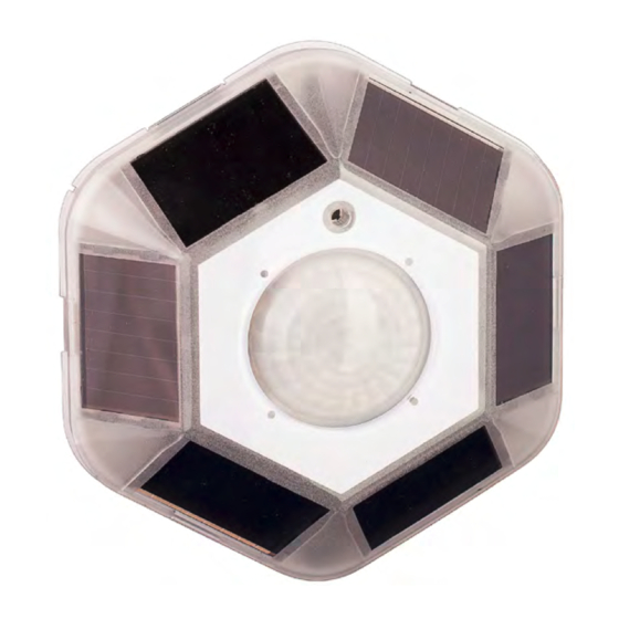
Wireless Motion Sensor for Occupancy / Vacancy Detection
This guide covers all models of MOS-21 sensor.
The MOS-21 product family includes:
MOS-21UA Motion Sensor with 902 MHz radio with short range lens
MOS-21UB Motion Sensor with 902 MHz radio with large range lens
MOS-21UC Motion Sensor with 902 MHz radio with high bay lens
MOS-21CA Motion Sensor with 315 MHz radio with short range lens
MOS-21CB
MOS-21CC
MOS-21YA
MOS-21YB
MOS-21YC
The package includes the occupancy sensor and installation guide.
MOS-21 Sensor Description
The 21 series MOS sensor (also referred to as the sensor in this guide) is a
wireless, energy harvesting, ceiling mount, passive infared (PIR) occupancy
sensor. Used for indoor applications, the detector is optimized for ceiling heights
of 8 - 10 feet (2.4 - 3m).
NOTE: The MOS is a solar powered device that absorbs solar energy storing it
for use during low light periods. Before assigning the MOS device to a receiver/
controller, the device should be exposed to a good light source for a minimum of
5 minutes or install the start assist battery.
with integrated diagnostic tools
INSTALLATION GUIDE
Motion Sensor with 315 MHz radio with large range lens
Motion Sensor with 315 MHz radio with high bay lens
Motion Sensor with 868 MHz radio with short range lens
Motion Sensor with 868 MHz radio with large range lens
Motion Sensor with 868 MHz radio with high bay lens
MOS-21
Advertisement
Table of Contents

Related Manuals for echoflex MOS-21 Series


Summary of Contents for echoflex MOS-21 Series
- Page 1 MOS-21 Wireless Motion Sensor for Occupancy / Vacancy Detection with integrated diagnostic tools INSTALLATION GUIDE This guide covers all models of MOS-21 sensor. The MOS-21 product family includes: MOS-21UA Motion Sensor with 902 MHz radio with short range lens MOS-21UB Motion Sensor with 902 MHz radio with large range lens MOS-21UC Motion Sensor with 902 MHz radio with high bay lens MOS-21CA Motion Sensor with 315 MHz radio with short range lens MOS-21CB Motion Sensor with 315 MHz radio with large range lens MOS-21CC Motion Sensor with 315 MHz radio with high bay lens MOS-21YA Motion Sensor with 868 MHz radio with short range lens MOS-21YB...
-
Page 2: Sensor Operation
Sensor Operation The MOS-21 sensor monitors motion in interior spaces. The sensor is powered by solar energy from natural or artificial light sources. The solar energy is transformed into electrical energy which is then stored providing a continuous power source for the sensor. Powered by six solar cells, the sensor can operate without battery backup for up to 225 hours. The sensor will operate even with a brief exposure to light, however for best results the sensor should be mounted in a location with exposure for 2 hours of natural or artificial light (160 - 500 lux or 16-50 fc) on a daily basis. A battery (CR2032) must be installed in the MOS-21xC sensor for use in high bay applications. The motion sensor supports the Occupancy Sensor EnOcean profile A5-07-01. The sensor will transmit occupancy or vacancy depending on the occupancy state of the room. The sensor will broadcast occupancy immediately upon a state change from vacant to occupied. The sensor broadcasts a telegram when movement is detected and repeats occupied telegrams with a minimum 100... -
Page 3: Sensor Range
Sensor Range The sensor is offered with three different lens. There is a lens with a high sensor ray density pattern (A) suitable for small motion detection, however this lens has shorter detection range. The second lens (B) has a broader range but is less sensitive for small motion detection. The third lens (C) is for high ceiling applications, for example: high bay warehouses. Short Range Lens (A) 1000 sq.ft @ 8 ft. Large Range Lens (B) 1900 sq.ft @ 9 ft. High Bay Lens (C) 6300 sq.ft @ 40 ft. Mounting the Sensor The mounting location of the sensor is important as this will directly affect the receivers reception of the telegrams. Before installing, refer to the sections in the guide detailing the installation of wireless devices, layout tips and test... - Page 4 1. Select a location to the mount the sensor on the ceiling by identifying the movement patterns that will be the most common in the space. • For smaller office spaces where hand motion on a desktop is common, locate the sensor off to one end of the desk, in line with the desk edge or slightly behind so the PIR lens has direct line-of-sight to the keyboard desktop area. Insure that the PIR lens does not have direct line-of-sight out a doorway where walk-by traffic could trigger the sensor. • Larger offices where larger body motion is more common, placement of the sensor is less critical. 2. For the best sensor performance, mount the sensor so at least one of the solar cells is facing a light fixture. The sensor will operate in low light levels however for best performance, a minimum of 4 foot candles must be maintained. If the controlled lights in the space are dimmable either manually of via daylight harvesting, insure the light level at the lowest dimmed level meets this 4 FC requirement. If the light value does not meet this requirement, install a battery. 3. Remove the cover by pushing upwards on the cover. Using a small screwdriver for leverage, insert under the clear plastic lens at one of the relief tabs in the base plate and pull up. You will need to repeat with at least two tabs until the lens pops free. 4. Choose a mounting method. The sensor can be mounted: • With the screws and anchors (not provided) to a wall-board ceiling. Use a pencil to mark the mounting base key hole locations and remove the sensor. Using a drill, bore the two holes and insert the anchors. Install the screws, leaving them loose while you place the sensor. Tighten the screws. • With double sided tape or Velcro™, not provided. Cut two lengths of tape and remove the backing. Place on the mounting surface of the sensors back plate, pressing down. Remove the backing from the tapes other side and place the sensor on the ceiling surface, pressing firmly. 5. Replace the sensor cover aligning the button hole with the teach button and press in place. 6. Refer to the section titled Linking the Sensor to a Receiver.
-
Page 5: Test Operating Modes
1. Using a small screwdriver for leverage, insert under the clear plastic lens at one of the relief tabs in the base plate and pull up. You will need to repeat with at least two tabs until the lens pops free. 2. Using a finger, remove the old battery by pulling the battery free from the holder. Do not use a screwdriver. 3. Insert the new battery and press in place with your finger. 4. Replace the lens over the sensor aligning the button hole with the teach button and press in place. Test Operating Modes The following tests can be selected when in test mode: • Light Level Test • Range Confirmation Test • Walk Test Mode, • Sensitivity Adjust Mode Light Level Test: This test provides visual feedback of the immediate energy produced by the solar panels. 1. To enter Light Level Test mode, press and hold the teach button until the green LED begins to blink (about 6 seconds - LEDs are located on right hand side of the solar panel). 2. -
Page 6: Walk Test Mode
Note: • Range Confirmation is only available with “F series” or later Echoflex Controllers. • The MOS must be at full charge and/or have the battery installed for Range Confirmation Tests energy requirements. • Only one receiver can be linked to the sensor for proper operation of the test. • Disable repeaters in range for proper test operation. All three LED’s will blink (for 1 second) in this test mode when the sensor transmits or receives a Range Confirmation Telegram followed by the sensor displaying the linked signal strength status for 2.5 seconds, see table below. Signal Strength Green - Solid 2.5 sec... - Page 7 Setting Indication High Green LED blinking Medium Amber LED blinking Red LED blinking To select a setting press and hold the test button for 6 seconds when the desired LED is blinking. To exit without saving, allow the test to time-out in 60 seconds or press the Link button to exit immediately without saving. Wireless System Layout Hints • Avoid locating transmitters and receivers on the same wall. • Avoid locating transmitters and receivers where the telegrams must penetrate walls at acute angles. This increases the material the telegram must pass through reducing the signal power. • Avoid large metal obstructions as they create radio shadows. Place receivers in alternate locations to avoid the shadow or use repeaters to go around the obstacle. • Do not locate receivers close to other high frequency transmitters. • Leave at least 3’ between the receiver and any other source of interference including, ballasts, LED drivers, computers, video equipment, Wi-Fi/LAN routers, GSM modems and monitors.
-
Page 8: Regulatory Statements
Regulatory Statements FCC Part 15.231 (315 and 902 MHz models only) Contains FCC ID: TCM300C or TCM300U The enclosed device complies with Part 15 of the FCC Rules. Operation is subject to the following two conditions: (I.) this device may not cause harmful interference and (ii.) this device must accept any interference received, including interference that may cause undesired operation. IC RSS-210: (315MHz and 902 MHz models only) Copyright 2011-2015 Echoflex Solutions, Inc. | Specifications subject to change without notice. Document # 8DC-5492 | Revision 1.4 | 8188M21-5492-1 | Rev C Echoflex Solutions, Inc. #1, 38924 Queens Way | Squamish | BC | Canada | V8B 0K8 echoflex Toll Free: 888-324-6359 | Phone: (778) 733-0111 | Fax: (604) 815-0078 Email: info@echoflexsolutions.com | www.echoflexsolutions.com...