Table of Contents
Advertisement
Quick Links
P O W E R I N G
T E C H N O L O G Y
OPERATING MANUAL
POWER DISTRIBUTION PANELS
DPBF1U & DPGF1U SERIES
© 2019 UNIPOWER LLC
Document Number: DPBF-DPGF-MAN Rev. 5
All Rights Reserved
UNIPOWER, LLC
65 Industrial Park Rd
Dunlap, TN 37327
Phone: +1-954-346-2442
Toll Free: 1-800-440-3504
Web site:
www.unipowerco.com
Advertisement
Table of Contents

Related Manuals for Unipower DPBF1U Series

Summary of Contents for Unipower DPBF1U Series
- Page 1 P O W E R I N G T E C H N O L O G Y OPERATING MANUAL POWER DISTRIBUTION PANELS DPBF1U & DPGF1U SERIES © 2019 UNIPOWER LLC Document Number: DPBF-DPGF-MAN Rev. 5 All Rights Reserved UNIPOWER, LLC 65 Industrial Park Rd...
-
Page 2: Table Of Contents
DPBF1U & DPGF1U SERIES P O W E R I N G T E C H N O L O G Y OPERATING MANUAL DESCRIPTION CHK’d & APPR’d / DATE PCO# 45395 MM / 07-31-19 Contents 1.0 INTRODUCTION ........................4 2.0 FEATURES & OPTIONS .......................5 3.0 PRODUCT LINE ........................5 4.0 SAFETY &... - Page 3 DPBF1U & DPGF1U SERIES P O W E R I N G T E C H N O L O G Y OPERATING MANUAL FIGURES Figure 1. DPGF1U & DPBF1U Front Views Figure 2. Block Diagram Figure 3. DPBF1U Front Panel View Figure 4.
-
Page 4: Introduction
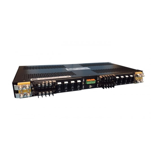
Figure 1 shows the two series of panels. The first is the DPGF1U Series which has 4 or 6 GMT fused circuits on both A and B sides. The second is the DPBF1U Series with up to 4 circuit breaker circuits on both A and B sides. -
Page 5: Features & Options
DPBF1U & DPGF1U SERIES P O W E R I N G T E C H N O L O G Y OPERATING MANUAL FEATURES & OPTIONS The following is a summary of the important features of the Series. Thin Height: 1.75 inches (1RU) ... -
Page 6: Safety & Industry Standards
God, negligence or the failure of customer to fully follow instructions with respect to installation, application or maintenance. For a complete text of UNIPOWER’s warranty conditions please request a copy from your local Sales Office. -
Page 7: Description Of Operation
DPBF1U & DPGF1U SERIES P O W E R I N G T E C H N O L O G Y OPERATING MANUAL DESCRIPTION OF OPERATION Power Distribution Circuits. A simplified schematic diagram of the distribution panels is shown in Figure 2. The battery input to each load connects to a high-current copper bus bar from which the individual fuses or circuit breakers distribute power to the loads. -
Page 8: Specifications
DPBF1U & DPGF1U SERIES P O W E R I N G T E C H N O L O G Y OPERATING MANUAL SPECIFICATIONS The following specifications are typical at 25°C unless otherwise noted. INPUT / OUTPUT ENVIRONMENTAL Panel Capacity ........... See Panel Configuration Table Operating Temp. -
Page 9: Configuration
Gray UNIPOWER recommends Bussman 401-1500-0040 White fuses for this panel. 401-1500-0050 Orange 401-1500-0060 Blue They may be ordered from 401-1500-0070 Green UNIPOWER using the part numbers 401-1500-0080 Red/White shown. 401-1500-0090 Green/Yellow Red/Blue 401-1500-0110 Green/White 401-1523-0000 DUMMY 401-1500-0100 Table 3. GMT Fuse Values Document Number: DPBF-DPGF-MAN Rev. - Page 10 DPBF1U & DPGF1U SERIES P O W E R I N G T E C H N O L O G Y OPERATING MANUAL DPBF1U Configuration Details Model No.: DPBF1U-A -B -- STANDARD CODE VOLTAGE & POLARITY BREAKERS 24/48V (polarity neutral) CODE AMPS 12V (polarity neutral)
-
Page 11: Front Panel Description
DPBF1U & DPGF1U SERIES P O W E R I N G T E C H N O L O G Y OPERATING MANUAL FRONT PANEL DESCRIPTION Front View. Figures 3 and 4 show the front of the DPBF1U and DPGF1U distribution panels respectively. -
Page 12: Figure 6. Output Barrier Strip Detail
AWG wire sizes from no. 1 to 8 and one- or two- hole lugs. These lugs can be ordered directly from the manufacturer, Panduit Corp., using the model numbers shown in table 4. A standard kit of four two-hole crimp type lugs for no. 6 AWG copper wire is available from UNIPOWER. Order kit no. 775-1434-0000. WIRE .25DIA. -
Page 13: Figure 7. Alarm Contact & Ground Detail
ALARM DPBF1U & DPGF1U SERIES P O W E R I N G T E C H N O L O G Y OPERATING MANUAL A Side Breakers Alarm LEDs B Side Breakers REAR VIEW Form C Relay Contact Outputs. The center of the back panel has connections to the Form C relay contact outputs for connection to external audible or visual alarm circuits. -
Page 14: Unpacking And Inspection
10.3 UNIPOWER will cooperate fully in case of any shipping damage investigation. Always save the packing materials for later use in shipping the unit. Never ship the rectifier 10.4... -
Page 15: Setup And Testing
DPBF1U & DPGF1U SERIES P O W E R I N G T E C H N O L O G Y OPERATING MANUAL The Form C relay contact output connections are made to the spring clamp terminal blocks. See Section 9.5. The chassis ground connection is made to the no. 8-32 stud. See Section 9.6. - Page 16 What actions have been taken since the problem occurred? This document is believed to be correct at time of publication and UNIPOWER LLC accepts no responsibility for consequences from printing errors or inaccuracies. Specifications are subject to change without notice.
Need help?
Do you have a question about the DPBF1U Series and is the answer not in the manual?
Questions and answers