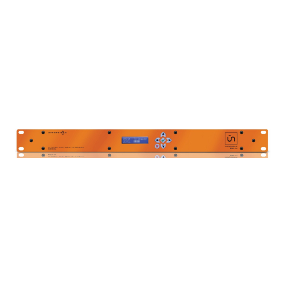
Summary of Contents for Attero Tech unD32 BoB
- Page 1 BoB 32 Channel Dante Break Out Box User Manual Date 04/22/15 Revision 02 Attero Tech, LLC 1315 Directors Row, Suite 107, Ft Wayne, IN 46808 Phone 260-496-9668 • Fax 260-496-9879 www.atterotech.com 614-00012...
- Page 2 Operation of this equipment in a residential area is likely to cause harmful interference, in which case the user will be required to correct the interference at his own expense. © Attero Tech LLC 2015 Page 1 614-00012 Rev 02...
- Page 3 BoB User Manual Credits Bonjour is a trademark of Apple Inc. Dante is a trademark of Audinate Pty Ltd. © Attero Tech LLC 2015 Page 2 614-00012 Rev 02...
-
Page 4: Table Of Contents
5 – Device Specifications ......................................16 5.1 – Architects and Engineering Spec..........................16 5.2 – Device Specifications .............................. 16 6 – LIMITED TWO YEAR WARRANTY .................................. 17 APPENDIX A – Reference Documents ................................A-1 © Attero Tech LLC 2015 Page 3 614-00012 Rev 02... -
Page 5: Overview
The unD32 comes supplied with the following: unD32 unit (710-00149-01) 24V DC Power Supply AC Power Cord (mains connector type determined by part number used to order the unD32) 32 Phoenix-style connector plugs (RIA 31369103) © Attero Tech LLC 2015 Page 4 614-00012 Rev 02... -
Page 6: Und32 Unit Block Diagram
BoB User Manual 1.2 – unD32 Unit Block Diagram Figure 3 - unD32 Block Diagram © Attero Tech LLC 2015 Page 5 614-00012 Rev 02... -
Page 7: Installation
In this mode, the local port can be used as a control port as it can access the device regardless of whether the unD32 is operating on its primary or secondary interface (only one of which will be active for audio transfers at any one time). © Attero Tech LLC 2015 Page 6... -
Page 8: Audio Connections
Connect the GNDs together through the cable shield. If the cable does not have a shield, use a free core instead. Leave the unD32 negative output floating. Figure 5 - unD32 Output to Single Ended Destination © Attero Tech LLC 2015 Page 7 614-00012 Rev 02... -
Page 9: Front Panel Operation
Output Channel respectively. *Note: The channel number wraps from 32 to 1 in the Up direction and 1 to 32 in the down direction. © Attero Tech LLC 2015 Page 8 614-00012 Rev 02... -
Page 10: Channel Select Screen
To transition to another channel or to the Volume Select screen the cursor needs to be in the first character of the Output Channel field. Pressing either the Left or Right buttons will accomplish this. © Attero Tech LLC 2015 Page 9... -
Page 11: Volume Select Screen
LCD goes to “sleep”. If changes have been made to the unD32 settings using the front panel and the unit is then powered down before the LCD has gone to “sleep”, any changes will be lost. © Attero Tech LLC 2015 Page 10... -
Page 12: Configuration Using A Gui
‘######’ is the last six characters of the devices MAC address. Configuration of the unD32 specific features is carried out using the Attero Tech unIFY unD32 Control Panel application. This application is available from the Attero Tech website (http://www.atterotech.com/). It should be used to examine and modify the device specific features such as channel volume and mute settings and master volume and master mute. - Page 13 If you agree to the license agreement, click the “I Accept…” checkbox then click next Enter the user name and Organization details. Then click the “Next” button. Next enter the installation folder. A default location is provided automatically. Click “Next” to continue. © Attero Tech LLC 2015 Page 12 614-00012 Rev 02...
- Page 14 The software will then being installing the files, showing a progress bar as it proceeds. If the installation completes successfully, you will see the screen above. Click finish to conclude the installation. © Attero Tech LLC 2015 Page 13 614-00012 Rev 02...
-
Page 15: Running Und32 Control Panel
4.3 – Running unD32 Control Panel To run the GUI, click on the unIFY unD32 icon under Attero Tech in your programs list. When the GUI opens, the screen above will be presented. The application will start in the offline state, noted in the status bar at the bottom of the application window. -
Page 16: Third Party Control
See the following link for instructions: http://www.itechtalk.com/thread11886.html Check that the device and the PC’s network card both have an IP address and they are both in the same network range. © Attero Tech LLC 2015 Page 15 614-00012 Rev 02... -
Page 17: Device Specifications
20 W maximum at 100V-240VAC Certifications: FCC Part 15 Class A, CE, UL. Compliant with AES48-2005 Grounding/EMI Guidelines Dimensions: 1.75” H x 19” W x 6” D Weight 5 lbs © Attero Tech LLC 2015 Page 16 614-00012 Rev 02... -
Page 18: Limited Two Year Warranty
LLC, shipping costs prepaid, within two year from the date of purchase. This Limited Warranty is governed by the laws of the State of Indiana. It states the entire liability of Attero Tech, LLC and the entire remedy of the purchaser for any breach of warranty as outlined above. -
Page 19: Appendix A - Reference Documents
BoB User Manual APPENDIX A – Reference Documents The following table lists the relevant reference documents. Document Title Revision DANTE Controller User’s Guide V1.0 unIFY Software API manual V1.0 © Attero Tech LLC 2015 Page A-1 614-00012 Rev 02...


Need help?
Do you have a question about the unD32 BoB and is the answer not in the manual?
Questions and answers