Baumer HUBNER BERLIN HMG10 Mounting And Operating Instructions
Absolute encoder ssi with magnetic sensing
Hide thumbs
Also See for HUBNER BERLIN HMG10:
- Mounting and operating instructions (32 pages) ,
- Operating manual (52 pages)

Related Manuals for Baumer HUBNER BERLIN HMG10


Summary of Contents for Baumer HUBNER BERLIN HMG10
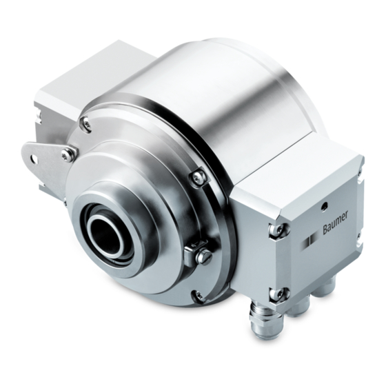
- Page 1 Mounting and operating instructions HMG10 • HMG10P Absolute encoder SSI with magnetic sensing...
-
Page 2: Table Of Contents
TABLE OF CONTENTS TABLE OF CONTENTS 1. IMPORTANT NOTES �������������������������������������������������������������������������������������������������������������1 1�1 Symbol guide ������������������������������������������������������������������������������������������������������������������1 1�2 Intended use �������������������������������������������������������������������������������������������������������������������1 1�3 Exclusion from liability ����������������������������������������������������������������������������������������������������1 1�4 Maintenance and service life ������������������������������������������������������������������������������������������2 1�5 Approvals and warranty ��������������������������������������������������������������������������������������������������2 1�6 Operating and storage temperature range ���������������������������������������������������������������������2 1�7 Disposal (environmental protection) �������������������������������������������������������������������������������2 2. - Page 3 TABLE OF CONTENTS 5. ELECTRICAL CONNECTION ����������������������������������������������������������������������������������������������13 5.1 Terminal significance ����������������������������������������������������������������������������������������������������13 5�2 SSI interface �����������������������������������������������������������������������������������������������������������������14 5�2�1 Data transfer �������������������������������������������������������������������������������������������������������14 5�2�2 Function „RESET“ ����������������������������������������������������������������������������������������������14 5�2�3 Function „Rotating direction“ ������������������������������������������������������������������������������14 5�3 Additional output incremental (option) ��������������������������������������������������������������������������15 5�3�1 Output signals ����������������������������������������������������������������������������������������������������15 5�3�2 Trigger level ��������������������������������������������������������������������������������������������������������15 5�4 Programming interface (only HMG10P) �����������������������������������������������������������������������16 5�5 LED function displays ���������������������������������������������������������������������������������������������������16 5�6 Switching characteristics speed switch (option) �����������������������������������������������������������17...
- Page 4 TABLE OF CONTENTS 7. DIMENSIONS �����������������������������������������������������������������������������������������������������������������������26 7�1 Blind hollow shaft ����������������������������������������������������������������������������������������������������������26 7�1�1 With radial terminal boxes ����������������������������������������������������������������������������������26 7.1.2 With radial flange connectors �����������������������������������������������������������������������������26 7�2 Through hollow shaft ����������������������������������������������������������������������������������������������������27 7�2�1 With radial terminal boxes ����������������������������������������������������������������������������������27 7.2.2 With radial flange connectors �����������������������������������������������������������������������������27 7�3 Cone shaft ��������������������������������������������������������������������������������������������������������������������28 7�3�1 With radial terminal boxes ����������������������������������������������������������������������������������28 7.3.2 With radial flange connectors �����������������������������������������������������������������������������28 8.
-
Page 5: Important Notes
IMPORTANT NOTES IMPORTANT NOTES Symbol guide Warning Disregarding could result in serious injury, death or damage to property Attention Disregarding could result in damage to property or damage/malfunction of the device Information Additional information and recommendations Intended use The encoder HMG10/HMG10P is a precision measurement device for the acquisition of speed/position information for the control of drive units and the provision of electronic out- put signals for downstream devices�... -
Page 6: 1�4 Maintenance And Service Life
Whenever possible, waste electrical and electronic equipment should be disposed locally at the authorized collection point� If necessary, Baumer gives customers the opportunity to dispose of Baumer products professionally� For further information see www�baumer�com�... -
Page 7: Safety And Attention Instructions
SAFETy AND ATTENTION INSTRUCTIONS SAFETY AND ATTENTION INSTRUCTIONS Safety instructions Explosion risk Spark formation can cause a fire or an explosion. » Do not use the device in areas with explosive and/or highly inflammable materials. They may explode and/or catch fire by possible spark formation. Risk of serious injuries due to rotating shafts Hair and clothes may become tangled in rotating shafts� Touching the rotating parts can cause extremely serious injuries� »... -
Page 8: 2�2 Attention Instructions For Mounting And Operation
SAFETy AND ATTENTION INSTRUCTIONS Attention instructions for mounting and operation Risk of destruction due to electrostatic charge Electronic parts contained in the device are sensitive to high voltages� » Do not touch plug contacts or electronic components� » Protect output terminals against external voltages� »... -
Page 9: Preparation
PREPARATION PREPARATION Scope of delivery 7a 6a 6b 6d 6e 6f Housing Blind hollow shaft* or cone shaft*: Cover Blind hollow shaft or cone shaft with spanner flat 17 a/f Torx/slotted screw M4x10 mm, DIN 7964 7b Clamping element, not for cone shaft LED function indicators Through hollow shaft*: Earthing strap, length ~230 mm... -
Page 10: 3�2 Required Accessories For Mounting/Dismounting (Not Included In Scope Of Delivery)
PREPARATION Required accessories for mounting/dismounting (not included in scope of delivery) Connecting cables and respective mating connectors are required for the electrical connection� Details see section 6.2, page 23� Torque arm, length L / order number Standard: 67���70 mm / 11043628 125 (±5) mm, can be shortened to ≥71 mm / 11004078 440 (+20/-15) mm, can be shortened to ≥131 mm / 11002915 Insulated:... -
Page 11: Mounting
MOUNTING / POSITIONING THE SUPPORT PLATE MOUNTING Positioning the support plate TX 20 Loosen the screw 360° Tighten the screw = 2���3 Nm Mounting the torque arm at the device » Note the mounting instructions for the torque arm in section 4.4, page 11�... -
Page 12: 4�3 Mounting To Drive Shaft
MOUNTING / MOUNTING TO DRIVE SHAFT Mounting to drive shaft 4.3.1 Blind hollow shaft Service life restrictions and angle error by runouts High runout of the drive shaft can cause device angle error, see section 4.5, page 12� High runout of the drive shaft can cause vibrations, which can shorten the ser- vice life of the device�... -
Page 13: 4�3�2 Cone Shaft
MOUNTING / MOUNTING TO DRIVE SHAFT 4.3.2 Cone shaft Service life restrictions and angle error by runouts High runout of the drive shaft can cause device angle error, see section 4.5, page 12� High runout of the drive shaft can cause vibrations, which can shorten the ser- vice life of the device�... -
Page 14: 4�3�3 Through Hollow Shaft
MOUNTING / MOUNTING TO DRIVE SHAFT 4.3.3 Through hollow shaft Service life restrictions and angle error by runouts High runout of the drive shaft can cause device angle error, see section 4.5, page 12� High runout of the drive shaft can cause vibrations, which can shorten the ser- vice life of the device�... -
Page 15: 4�4 Drive Side Mounting Of The Torque Arm
MOUNTING / DRIVE SIDE MOUNTING OF THE TORqUE ARM Drive side mounting of the torque arm Service life restrictions and angle error by runouts A play of just ±0�03 mm, results in a runout of the device of 0�06 mm� That may lead to a large angle error, see section 4.5, page 12�... -
Page 16: 4�5 How To Prevent Measurement Errors
MOUNTING / HOW TO PREVENT MEASUREMENT ERRORS How to prevent measurement errors To ensure that the device operates correctly, it is necessary to mount it accurately as de- scribed in section 4�1 to 4�4, which includes correct mounting of the torque arm� The radial runout of the drive shaft should not exceed 0�2 mm (0�03 mm recommended), to prevent an angle error�... -
Page 17: Electrical Connection
ELECTRICAL CONNECTION / TERMINAL SIGNIFICANCE ELECTRICAL CONNECTION Terminal significance Voltage supply Ground Output signal channel 1 A− Output signal channel 1 inverted Output signal channel 2 (offset by 90° to channel 1) B− Output signal channel 2 inverted Zero pulse (reference signal) R−... -
Page 18: 5�2 Ssi Interface
ELECTRICAL CONNECTION / SSI INTERFACE SSI interface 5.2.1 Data transfer Clock Position Speed Data n-1...0 bit m-1...0 bit msb → lsb msb → lsb Clock frequency 100 kHz���2 MHz Monoflop time (t) 20 µs (internal) n, m Number of bits For continous clocking, the SSI word is transmitted only once followed by zero values (no ring register operation)�... -
Page 19: 5�3 Additional Output Incremental (Option)
ELECTRICAL CONNECTION / ADDITIONAL OUTPUT INCREMENTAL (OPTION) Additional output incremental (option) 5.3.1 Output signals At positive rotating direction 90° Zero pulse+ Zero pulse- 5.3.2 Trigger level Trigger level: TTL/RS422 High / Low: ≥2.5 V / ≤0.5 V Transmission length: ≤550 m @ 100 kHz Output frequency ≤600 kHz Trigger level: TTL/HTL (Vin = Vout) High / Low: ≥2.5 V / ≤0.5 V (TTL) ǀ ≥Ub -3 V / ≤1.5 V (HTL) Transmission length: ≤550 m @ 100 kHz (TTL) ǀ ≤350 m @ 100 kHz (HTL) -
Page 20: 5�4 Programming Interface (Only Hmg10P)
ELECTRICAL CONNECTION / PROGRAMMING INTERFACE (ONLy HMG10P) Programming interface (only HMG10P) Encoder parameter like resolution singleturn and/or multiturn (SSI), binary or gray code (SSI), additional output 1 and 2, switch-off and switch-on speeds can get and set via SA and SB� With the Z-PA�SDL�1 WLAN adapter, available as accessory, see section 6.1, it is possible to get access to the encoder via webbrowser�... -
Page 21: 5�6 Switching Characteristics Speed Switch (Option)
ELECTRICAL CONNECTION / SWITCHING CHARACTERISTICS SPEED SWITCH (OPTION) Switching characteristics speed switch (option) The factory setting of the switching speed for the HMG10P is 6000 rpm� The HMG10 without programming interface is delivered with the individually ordered fixed swit- ching speed� Event State of the speed switch output During initialisation High resistance (overspeed) After initialisation and speed ≤ -ns (off) -
Page 22: 5�7 Electrical Connection With Radial Terminal Boxes
ELECTRICAL CONNECTION / ELECTRICAL CONNECTION WITH RADIAL TERMINAL BOXES Electrical connection with radial terminal boxes 5.7.1 Cable connection To ensure the specified protection of the device the correct cable diameter must be used� Connecting cables are not in scope of delivery and can be ordered separately as ac- cessory, see section 6.2.1, page 23�... -
Page 23: 5�7�2 Assignment Connecting Terminal
ELECTRICAL CONNECTION / ELECTRICAL CONNECTION WITH RADIAL TERMINAL BOXES 5.7.2 Assignment connecting terminal Do not connect voltage supply to outputs! Danger of damage! Please, beware of possible voltage drop in long cable leads (inputs and out- puts)! 5.7.2.1 Connecting terminal first terminal box [A] Programming interface (only HMG10P) Additional output incremental 1 (option) dnu / SA... -
Page 24: Electrical Connection With Radial Flange Connectors
ELECTRICAL CONNECTION / ELECTRICAL CONNECTION WITH RADIAL FLANGE CONNECTORS Electrical connection with radial flange connectors 5.8.1 Cable connection mating connector M23 (accessory) To ensure the specified protection of the device the correct cable diameter must be used� Connecting cables and mating connectors are not in scope of delivery and can be ordered separately as accessory, see section 6, page 22�... -
Page 25: Assignment Flange Connectors
ELECTRICAL CONNECTION / ELECTRICAL CONNECTION WITH RADIAL FLANGE CONNECTORS 5.8.2 Assignment flange connectors Do not connect voltage supply to outputs! Danger of damage! Please, beware of possible voltage drop in long cable leads (inputs and out- puts)! 5.8.2.1 First flange connector [C] Programming interface (only HMG10P) Additional output incremental 1 (option) Flange connector M23 (male, 17-pin, clockwise) -
Page 26: Accessories
ACCESSORIES / Z-PA�SDL�1 WLAN ADAPTER: PROGRAMMING DEVICE FOR HMG10P ACCESSORIES Z-PA.SDL.1 WLAN adapter: Programming device for HMG10P The Z-PA�SDL�1 WLAN adapter is a programming device for programming and monitoring HMG10P/PMG10P series encoders� The following encoder parameters can be parameterized (depending on the version of the encoder): •... -
Page 27: 6�2 Sensor Cable And Mating Connector
ACCESSORIES / SENSOR CABLE AND MATING CONNECTOR Sensor cable and mating connector 6.2.1 Sensor cable HEK 8 - Sensor cable with 10 wires for encoder 2 wires AWG21 (power supply), 4 twisted pair signal wires AWG24 (signal), cable length on request� HEK 17 - Sensor cable with 16 wires for encoder 2 wires AWG 21 (power supply), 3 twisted pair signal wires AWG35 (signal), 4 wires AWG35 (signal), 4 wires AWG31 (data),... -
Page 28: 6�2�3 Mating Connector M23, 17-Pin With Sensor Cable Hek 17
ACCESSORIES / SENSOR CABLE AND MATING CONNECTOR 6.2.3 Mating connector M23, 17-pin with sensor cable HEK 17 6.2.3.1 For version without additional output incremental Mating connector M23, 17-pin with sensor cable HEK 17, 11 pins assigned (2x pow- er supply, 1x internal shield, 4x signal, 4x data), female contacts, counter-clockwise (CCW) Suitable for first flange connector [C], see section 5.8.2.1�... -
Page 29: 6�2�3�2 For Version With Additional Output Incremental
ACCESSORIES / SENSOR CABLE AND MATING CONNECTOR 6.2.3.2 For version with additional output incremental Mating connector M23, 17-pin with sensor cable HEK 17, 17 pins assigned (2x power supply, 1x internal shield, 10x signal, 4x data), female contacts, counter-clockwise (CCW) Suitable for first flange connector [C], see section 5.8.2.1�... -
Page 30: Dimensions
DIMENSIONS / BLIND HOLLOW SHAFT DIMENSIONS Blind hollow shaft 7.1.1 With radial terminal boxes Programming interface Additional output incremental 2 (option) (only HMG10P) Speed switch (option) Additional output ød incremental 1 (option) 53 65�5 Accessory Positive rotating direction 7.1.2 With radial flange connectors ød Positive 53 65�5... -
Page 31: 7�2 Through Hollow Shaft
DIMENSIONS / THROUGH HOLLOW SHAFT Through hollow shaft 7.2.1 With radial terminal boxes Programming interface (only HMG10P) Additional output incremental 2 (option) Additional output Speed switch (option) incremental 1 (option) ød = 16 , 20 Accessory Positive rotating direction 7.2.2 With radial flange connectors Positive rotating direction... -
Page 32: 7�3 Cone Shaft
DIMENSIONS / CONE SHAFT Cone shaft 7.3.1 With radial terminal boxes Programming interface Additional output incremental 2 (option) (only HMG10P) Speed switch (option) Additional output incremental 1 (option) Accessory Positive rotating direction 7.3.2 With radial flange connectors Positive rotating direction Accessory Additional output incremental 2 (option) -
Page 33: Dismounting
DISMOUNTING / BLIND HOLLOW SHAFT OR CONE SHAFT DISMOUNTING Risk of serious injuries Disconnect all electrical connections before dismounting� Blind hollow shaft or cone shaft Pictures showing the device with blind hollow shaft� The dismounting steps be identical with cone shaft� 8.1.1 Step 1 17 mm... -
Page 34: 8�1�3 Step 3
DISMOUNTING / BLIND HOLLOW SHAFT OR CONE SHAFT 8.1.3 Step 3 17 mm 6 mm 8.1.4 Step 4 30/35 MB244EN - 11171691, 19A2, Baumer_HMG10-SSI_II_EN... -
Page 35: 8�2 Through Hollow Shaft
DISMOUNTING / THROUGH HOLLOW SHAFT Through hollow shaft TX 10 Loosen the screw 1�6x8 mm 10 mm MB244EN - 11171691, 19A2, Baumer_HMG10-SSI_II_EN 31/35... -
Page 36: Technical Data
TECHNICAL DATA TECHNICAL DATA Technical data - electrical ratings Voltage supply 4,75���30 VDC Short-circuit proof Consumption w/o load ≤100 mA (SSI) Initializing time ≤500 ms after power on Interface Steps per turn 1048576 / 20 Bit Number of turns 1048576 / 20 Bit Additional outputs Square-wave TTL/HTL, TTL/RS422 Sensing method Magnetic Code Gray (factory setting) or binary... -
Page 37: 9�3 Technical Data - Mechanical Design
TECHNICAL DATA Technical data - mechanical design Size (flange) ø105 mm Flange Support plate, 360° freely positionable Protection DIN EN 60529 IP66/IP67 Operating speed ≤12000 rpm Range of switching speed ns (off) = ±2���12000 rpm, (HMG10P: factory setting 6000 rpm) Operating torque typ� 10 Ncm Rotor moment of inertia 950 gcm Admitted shaft load... - Page 38 MB244EN - 11171691, 19A2, Baumer_HMG10-SSI_II_EN...
- Page 39 MB244EN - 11171691, 19A2, Baumer_HMG10-SSI_II_EN...
- Page 40 Baumer Hübner GmbH P.O. Box 12 69 43 · 10609 Berlin, Germany Phone: +49 (0)30/69003-0 · Fax: +49 (0)30/69003-104 info@baumerhuebner.com · www.baumer.com/motion MB244EN - 11171691, 19A2 (19�09�2019), Baumer_HMG10-SSI_II_EN...
Need help?
Do you have a question about the HUBNER BERLIN HMG10 and is the answer not in the manual?
Questions and answers