Greenheck SQ Series Installation, Operation And Maintenance Manual
Direct drive centrifugal inline fans
Hide thumbs
Also See for SQ Series:
Advertisement
Quick Links
READ AND SAVE THESE INSTRUCTIONS
®
Installation, Operation and Maintenance Manual
Installation
Upon receiving unit, check for any damage and report it immediately to shipper. Also check that all accessory items are accounted for.
Move fan to desired location and determine position of access panels, discharge, and motor. Make sure inlet and outlet have at least
2.5 times the wheel diameter (duct diameter) before any obstructions like an elbow or transaction. Attach fan to suitable framework as
specified (hanging or base vibration isolators are recommended). See chart below for dimensions of vibration isolator centerlines
(Fig. 1). See Fig. 2 for physical dimensions.
The voltage rating of the motor must be checked for compatibility to supply voltage prior to final electrical connection. Electrical lead-
in wires are then connected to the factory supplied safety disconnect switch. All wiring must conform to local and national codes.
Vibration Isolator Dimensional Data
A
C
A
C
SQ Dimensional Data
A
1in.
C sq.
Pre-Starting Checks
Check all fasteners for tightness. The
wheel should rotate freely and be
aligned as shown in Fig. 3. Wheel
position is preset and the unit tested
at the factory. However, movement
may occur during shipment, and
realignment may be necessary.
Centering (height alignment) may be
accomplished by loosening the set
screws in the wheel and moving the
wheel to desired position.
Maintenance
Motor maintenance is generally limited to cleaning and lubrication (where applicable). Cleaning should be limited to exterior surfaces
only. Removing dust buildup on motor housing ensures proper motor cooling. Greasing of motors is only intended when fittings are
provided. Many fractional motors are permanently lubricated and should not be lubricated after installation. Motors supplied with
grease fittings should be greased in accordance with manufacturer's recommendations. With motor temperatures under 104°F (40°C),
the grease should be replaced after 2000 hours of running time as a general rule.
Wheels require very little attention when moving clean air. Occasionally, oil and dust may accumulate causing imbalance. When this
occurs, the wheel and housing should be cleaned to ensure smooth and safe operation.
All fasteners should be checked for tightness each time maintenance checks are performed prior to restarting unit.
A proper maintenance program will help these units deliver years of dependable service.
A
B
A
B
B
Fig. 1
B sq.
1in.
B sq.
C sq.
Fig. 2
Overlap 1/4 in.
SQ
100-160
SQ
60-95
Gap 1/8 in.
Fig. 3
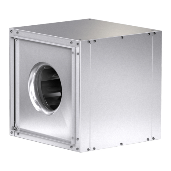
Model SQ Direct Drive
Centrifugal Inline Fans
D
B
D
Unit Size
A
60-75
13
80-95
16
100
21
120
21
130
21
140
22
160
26
All dimensions are in inches.
Wheel Rotation
Direction of wheel rotation is
critical. Reversed rotation will
result in poor air performance,
motor overloading and possible
burnout. Check wheel rotation
all SQ fans have CW wheel
(
rotation when viewed from top of fan)
momentarily energizing the unit. Rotation should be
clockwise as shown in Fig. 4 and correspond to the
rotation decal on the unit.
PN 453077
Unit Size
A
B
C
5
3
1
60-75
10
/
16
/
14
8
4
1
3
1
80-95
13
/
19
/
17
4
4
5
3
1
100
18
/
21
/
19
8
4
5
3
1
120
18
/
23
/
21
8
4
5
3
1
130
18
/
25
/
23
8
4
1
3
1
140
19
/
27
/
25
2
4
1
1
160
23
/
31
28
2
All dimensions are in inches.
Material
Approx. Unit
B
C
Thickness (ga.) Weight (lbs.)
7
12
8
/
20
8
7
15
11
/
20
8
7
17
13
/
20
8
7
19
15
/
20
8
7
21
17
/
20
8
7
23
19
/
18
8
7
26
22
/
18
8
Fig. 4
by
D
7
/
8
/
2
8
7
/
11
/
2
8
7
/
13
/
2
8
7
/
15
/
2
8
7
/
17
/
2
8
7
/
19
/
2
8
7
/
22
/
2
8
25
40
60
75
90
105
130
Advertisement

Related Manuals for Greenheck SQ Series


Summary of Contents for Greenheck SQ Series
- Page 1 READ AND SAVE THESE INSTRUCTIONS PN 453077 Model SQ Direct Drive Centrifugal Inline Fans ® Installation, Operation and Maintenance Manual Installation Upon receiving unit, check for any damage and report it immediately to shipper. Also check that all accessory items are accounted for. Move fan to desired location and determine position of access panels, discharge, and motor.
- Page 2 WARRANTY Greenheck warrants this equipment to be free from defects in material and workmanship for a period of one year from the purchase date. Any units or parts which prove to be defective during the warranty period will be replaced at our option when returned to our factory, transportation prepaid.
Need help?
Do you have a question about the SQ Series and is the answer not in the manual?
Questions and answers