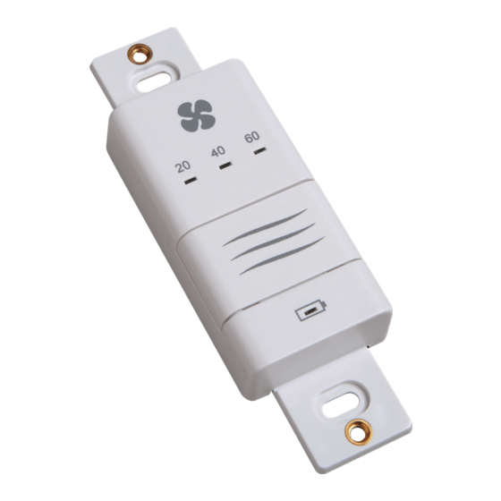
Greenheck ASSURE-120S-S1 Installation, Operation And Maintenance Manual

Greenheck ASSURE-120S-S1 Installation, Operation And Maintenance Manual

Residential energy recovery ventilators

Advertisement

®
Installation, Operation and Maintenance Manual
Please read and save these instructions for future reference. Read carefully before attempting to assemble, install, operate or
maintain the product described. Protect yourself and others by observing all safety information. Failure to comply with these
instructions will result in voiding of the product warranty and may result in personal injury and/or property damage.

Table of Contents

Shipping and Packing List.....................................................................................................................
General Information...............................................................................................................................
Model Numbers and Descriptions.........................................................................................................
Model Number Nomenclature Breakdown............................................................................................
Terms and Definitions............................................................................................................................
Application............................................................................................................................................
Required Tools and Materials................................................................................................................
Specifications........................................................................................................................................
Optional Fan Curve Speeds..................................................................................................................
Dimensional Drawings...........................................................................................................................
Defrost Overview...................................................................................................................................
Required Ventilation...............................................................................................................................
How the Dehumidistat Works................................................................................................................
Two-Speed Switch with Intermittent Mode (435246).............................................................................
Two-Speed Switch with Humidity Sensor (435245)...............................................................................
PrecisionSYNC Control (435244)..........................................................................................................
20/40/60 Minute Timer (435247)...........................................................................................................
20/40/60 Minute Wireless Timer (435248).............................................................................................
Wireless Repeater (435249)...................................................................................................................
Overview of Installation Methods..........................................................................................................
Connecting the Ductwork......................................................................................................................
Shaping Ducting to Fit Oval Ports.........................................................................................................
Installation Methods - Simplified (Return/Return).................................................................................
Installation Methods - Partially Dedicated.............................................................................................
Installation Methods - Fully Dedicated..................................................................................................
Unit Installation Location and Restrictions............................................................................................
Suspending the Unit..............................................................................................................................
Mounting the Unit..................................................................................................................................
Installing the Drain Connection (Optional).............................................................................................
Installing Drain Plug (Optional)..............................................................................................................
ERV Dual Intake and Exhaust Hood Kit.................................................................................................
Terminal Blocks.....................................................................................................................................
Installation of Controls...........................................................................................................................
Installation and Operation of 20/40/60 Minute Wireless Timer (435248)..............................................
Installation and Pairing of Wireless Repeater (435249).........................................................................
Installation of 20/40/60 Minute Timer (435247).....................................................................................
Installation of Third Party Mechanical Timers.......................................................................................
Interlocking ERV to Air Handler/Furnace Blower...................................................................................
Electrical Connections...........................................................................................................................
Unit Dip Switch Orientation...................................................................................................................
Adjusting the EC Motor (SYNC-110SE-S1)...........................................................................................
Balancing the Airflows...........................................................................................................................
Manual Balancing..................................................................................................................................
Precision Balancing...............................................................................................................................
Troubleshooting.....................................................................................................................................
Homeowner Maintenance Information..................................................................................................
®
Models ASSURE-120S-S1, SYNC-110SE-S1,
SYNC-180SCE-S1 and SYNC-270TCE-S1
Residential Energy Recovery Ventilators
2
2
2
3
3
3
3
4
6
7
8
9
10
11
11
12
13
13
13
14
14
14
15
16
17
18
18
19
19
20
20
21
21
22
23
24
24
24
25
28
29
29
29
31
32
33
1

Advertisement

Table of Contents
loading

Summary of Contents for Greenheck ASSURE-120S-S1

  • Page 1: Table Of Contents

    Models ASSURE-120S-S1, SYNC-110SE-S1, SYNC-180SCE-S1 and SYNC-270TCE-S1 Residential Energy Recovery Ventilators ® Installation, Operation and Maintenance Manual Please read and save these instructions for future reference. Read carefully before attempting to assemble, install, operate or maintain the product described. Protect yourself and others by observing all safety information. Failure to comply with these instructions will result in voiding of the product warranty and may result in personal injury and/or property damage.
  • Page 2: Shipping And Packing List

    1 - Assembled ventilator 1 - Accessories Bag assembly contains the following: Table 1. Accessories Bag Assembly Contents UNIT NAME MODEL NUMBER CONTENTS ASSURE120 ASSURE-120S-S1 1x Ventilation Label 4x Mounting Brackets 8x Screws SYNC110 SYNC-110SE-S1 1x Ventilation Label 4x Mounting Brackets...
  • Page 3: Model Number Nomenclature Breakdown

    Model Number Nomenclature Breakdown Example Model Number: SYNC–180SCE – S1 Revision Configuration (Mirror or Standard) Motor Type (ECM or Blank) Climate (Cold or Blank) Port Location (Side or Top) Gross Exhaust Rated CFM @ 0.4 in. wg ERV Family Terms and Definitions •...
  • Page 4: Specifications

    Specifications Table 3. Specifications Specifications Single−Core ERV Units Model No. ASSURE-120S-S1 SYNC-110SE-S1 SYNC-180SCE-S1 SYNC-270TCE-S1 Unit Weight in pounds 34 (15) 34 (15) 42 (19) 57 (26) (kilograms) Unit Dimensions Refer to “Dimensional Drawings” on page 7. High Speed (HVI Certified)
  • Page 5 Specifications Table 3. Specifications (continued) Specifications Single-Core ERV Units Model No. ASSURE-120S-S1 SYNC-110SE-S1 SYNC-180SCE-S1 SYNC-270TCE-S1 Number of speeds available with PrecisionSYNC Control (435244) Ventilator Type Energy Recovery Energy Recovery Energy Recovery Energy Recovery Energy Recovery Core Enthalpic Enthalpic Enthalpic Enthalpic...
  • Page 6: Optional Fan Curve Speeds

    Optional Fan Curve Speeds Table 4. Optional Fan Curves Speeds (Factory Tested) Single-Core ERV Units Model No. ASSURE-120S-S1 SYNC-110SE-S1 SYNC-180SCE-S1 SYNC-270TCE-S1 Speed 5 - High IN. WG (PA) 0.1 (25) 0.2 (50) 0.3 (75) 0.4 (100) 0.5 (125) 0.6 (150) 0.7 (175)
  • Page 7: Dimensional Drawings

    Stale Air from Inside Fresh Air to Inside 5 in. (125 mm) 9-3/4 in. (248 mm) 20 3/4 in. (527 mm) Core Collars Filters Figure 1. ASSURE-120S-S1 & SYNC-110SE-S1 DOOR CLOSED DOOR OPEN VIEW DOOR CLOSED VIEW SIDE VIEW Airflow: Motorized Impellers...
  • Page 8: Defrost Overview

    27°F (−3°C). Fan Defrost Applicable Units: ASSURE-120S-S1, SYNC-110SE-S1, and SYNC-180SCE-S1 During defrost the supply fan shuts off while the exhaust fan continues to operate. This allows the heat from the exhaust air to defrost the unit’s core. During the defrost portion of the cycle, the unit operates with only exhaust ventilation. After the defrost portion of the cycle, the supply fan powers on and operates with balanced ventilation.
  • Page 9: Required Ventilation

    Required Ventilation ASHRAE • ASHRAE 62.2-2019 is a national standard that provides methods for achieving acceptable indoor air quality in typical residences. It was developed and is maintained by the American Society of Heating and Air-Conditioning Engineers (ASHRAE). • This standard recommends Dwelling-Unit Ventilation, which is a mechanical exhaust system, supply system, or combination thereof.
  • Page 10: How The Dehumidistat Works

    How the Dehumidistat Works When using either the Two-Speed Switch with Humidity Sensor (435245) or the PrecisionSYNC Control (435244) a built-in dehumidistat is present. The following information is provided on how it works. High indoor humidity levels, during the heating season, have become a problem in many well insulated, tight homes. Excessive condensation on the windows is a visual sign of high indoor humidity levels.
  • Page 11: Two-Speed Switch With Intermittent Mode (435246)

    Two-Speed Switch with Intermittent Mode (435246) The control offers the following features to control your home’s ventilation. 20 / 40 Mode Indicator Light • Two-speed fan setting (LOW / HIGH) Fan Speed On / OFF • Standby setting (fan OFF) Indicator Light •...
  • Page 12: Precisionsync Control (435244)

    PrecisionSYNC Control (435244) The control offers the most advanced features to control your home’s ventilation. • Five-speed fan setting • Standby setting (fan speed 0) • Electronic dehumidistat • 20/40/60 HIGH speed override button • Compatible with Wireless Timer • Easy to read back-lit LCD screen •...
  • Page 13: 20/40/60 Minute Timer (435247)

    20/40/60 Minute Timer (435247) Timers are available as wired or wireless. The timer will override the operational mode of the control (regardless of the setting) and initiate HIGH fan speed Ventilation for 20, 40 or 60 minutes. The ERV will return to the selected operational mode and fan speed setting upon completion of the timer cycle.
  • Page 14: Overview Of Installation Methods

    Overview of Installation Methods There are three methods of installation for the ERV: • Simplified installation - See “Installation Methods - Simplified (Return/Return)” on page 15. • Partially dedicated installation - See “Installation Methods - Partially Dedicated” on page 16. •...
  • Page 15: Installation Methods - Simplified (Return/Return)

    Installation Methods - Simplified (Return/Return) The simplified method draws stale air from the cold air return duct of the air handler/furnace and introduces an equal amount of fresh air farther downstream into the cold air return as illustrated in the following figures. Key Points The ERV unit must be balanced.
  • Page 16: Installation Methods - Partially Dedicated

    Installation Methods - Partially Dedicated The partially dedicated installation draws stale air from specific points in the house and introduces an equal amount of fresh air into the cold air return as illustrated in the following building figures. Key Points The ERV unit must be balanced.
  • Page 17: Installation Methods - Fully Dedicated

    Installation Methods - Fully Dedicated The fully dedicated installation draws stale air from specific points in the building and delivers fresh air to specific locations of the building. This system is not connected to an air handler/ furnace (see the following figures). KEY POINTS The ERV unit must be balanced.
  • Page 18: Unit Installation Location And Restrictions

    Unit Installation Location It is recommended that the ERV unit be located in a conditioned space where it will be possible to conveniently service the unit: • Complexity of work to install, • Freezing conditions in the attic, • Difficulty of access for service and cleaning. Sufficient clearance in front/below (depending on model) of the access door is required for servicing the air filters and core.
  • Page 19: Mounting The Unit

    Install the unit to the mounting surface, using the mounting brackets provided. Note: The ASSURE-120S-S1 and SYNC-110SE-S1 can only be ceiling mounted. The SYNC 180SCE-S1 can be either ceiling mounted or wall mounted.
  • Page 20: Installing Drain Plug (Optional)

    Installing Drain Plug (Optional) Applicable Unit: SYNC-270TCE-S1 The plugs are located in the ERV accessories bag. The plugs will be installed into the two holes located in the bottom tray of the ERV. They must be inserted from the inside of the unit to ensure the holes are fully sealed. Figure 24.
  • Page 21: Terminal Blocks

    NO NC DH Figure 27. Type A Figure 28. Type B The ASSURE-120S-S1, SYNC-110SE-S1 and SYNC-270TCE-S1 The SYNC-180SCE-S1 has a terminal block Type B as shown in have a terminal block Type A as shown in Figure 27. Figure 28.
  • Page 22: Installation And Operation Of 20/40/60 Minute Wireless Timer (435248)

    Installation and Operation of 20/40/60 Minute Wireless Timer (435248) NOTE: Wireless timers can only be used with wall mounted Two-Speed Switch or PrecisionSYNC Control (435244). The wireless timers may be installed onto a flush mounted electrical switch BOX A Back Plate BOX B box or it may be surface mounted onto a wall.
  • Page 23: Installation And Pairing Of Wireless Repeater (435249)

    Installation and Operation of 20/40/60 Minute Wireless Timer (435248) (cont’d.) Unpairing Remove the battery from the back of the wireless timer. Press and hold the button on the front of the 20/40/60 Minute Wireless Timer. While holding the button, reinsert the battery in the 20/40/60 Minute Wireless Timer. Continue holding the button until the LED under 40 begins flashing.
  • Page 24: Installation Of 20/40/60 Minute Timer (435247)

    Installation of 20/40/60 Minute Timer (435247) Installation Requirements The following installation requirements must be followed: • Timers mount in standard 2 x 4” (51 x 102 mm) electrical boxes. • If multiple timers are used, individually wire each timer to the unit. •...
  • Page 25: Electrical Connections

    Electrical Connections Plug the ERV directly into a standard designated 120 VAC electrical outlet. Use of an extension cord is NOT RECOMMENDED for this appliance. If further wiring is required, then a licensed electrician should make all electrical connections. It is recommended that a separate 15 A/120 V circuit be used.
  • Page 26 Unit Wiring Diagrams Applicable Unit: Applicable Unit: ASSURE-120S-S1 SYNC-110SE-S1 Figure 37. ASSURE-120S-S1 Wiring Diagram Figure 38. ERV-110E-S1 Wiring Diagram Residential Energy Recovery Ventilators ®...
  • Page 27 Unit Wiring Diagrams Applicable Units: SYNC-180SCE-S1 & SYNC-270TCE-S1 CAUTION: ELECTRICAL CONTROL PANEL, SERVICE BY ELECTRICIAN ONLY LEGEND Note: If any of the original wires supplied must be replaced, use only TEW certified wire. High Voltage Important: Control wiring low voltage communication 12V Low Voltage only.
  • Page 28: Unit Dip Switch Orientation

    3 (Hi 1). Refer to the specification pages in the manual for the air flow rates for speeds 5, 4 and 3. The factory setting is speed 5 (Hi 3). Applicable Units: ASSURE-120S-S1 and SYNC-110SE-S1 Table 12. Dip Switch Orientation for ASSURE-120S-S1 & SYNC-110SE-S1 SWITCH 1 Speed...
  • Page 29: Adjusting The Ec Motor (Sync-110Se-S1)

    ERV will not defrost properly The ASSURE-120S-S1 and SYNC-110SE-S1 are considered “factory balanced”. Due to the design of the unit, if the supply and exhaust static pressure of the duct installation are within 0.3 (in w.g.) of each other, the supply and exhaust airflows will be within 10% of each other.
  • Page 30 Manual Balancing (continued) Airflow: Stale Air to Outside Fresh Air from Outside Stale Air from Inside Fresh Air to Inside Figure Callouts: 1. 3/16 in. Hole 2. Pitot Tube Tip 3. Digital Manometer 4. Balancing Damper Steps: Drill a 3/16 in. hole in the duct, ideally 3 ft. downstream and 1 ft. upstream of any elbows or bends in the fresh air and stale air streams.
  • Page 31: Precision Balancing

    Precision Balancing Precision balancing enables the installer to dial in precise airflow to meet design and code requirements and the units will maintain the airflows through auto balancing after they are set. Balance Indicator – will Exhaust Supply Applicable units: Fan speed spin to indicate Airflow...
  • Page 32: Troubleshooting

    Troubleshooting Table 16. Troubleshooting Symptom Cause Solution • Clean exterior hoods or vents • Mesh on outside hoods plugged • Remove and clean both filter and core • Filters plugged • If unit is equipped with MERV 13 filters, • Core obstructed replace every 3 months.
  • Page 33: Homeowner Maintenance Information

    Homeowner Maintenance Information WARNING Electric Shock Hazard. Can cause injury or death. Disconnect all remote electrical power supplies before servicing. Unit may have multiple power supplies. Unit must be connected to a grounded power supply in accordance with national and local codes. Inspect exterior hoods and vents at least once a month and make sure exhaust and fresh air supply hoods are not blocked or restricted by leaves, grass, or snow.
  • Page 34 CIRCUIT BOARD MOTOR/CAPACITOR TERMINAL BLOCK TRANSFORMER FILTER MOTOR/CAPACITOR FILTER CORE Figure 42. Replacement Components Table 17. Replacement Parts Summary Replacement Part Description ASSURE-120S-S1 SYNC-110SE-S1 SYNC-180SCE-S1 SYNC-270TCE-S1 MERV-6 Filters (Packs of 2) 485462 485462 485464 485466 MERV-13 Filters (Packs of 4) 485463...
  • Page 35 As a result of our commitment to continuous improvement, Greenheck reserves the right to change specifications without notice. Product warranties can be found online at Greenheck.com, either on the specific product page or in the literature section of the website at Greenheck.com/Resources/Library/Literature.

This manual is also suitable for:

Sync-110se-s1Sync-180sce-s1Sync-270tce-s1

Table of Contents