Table of Contents
Advertisement
Quick Links
Advertisement
Table of Contents

Related Manuals for Hitecsa KUBIC RMXRBA HE Series


Summary of Contents for Hitecsa KUBIC RMXRBA HE Series
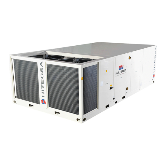
- Page 1 RMXRBA HE Heat Pump ROOF TOP UNITS – AXIAL FANS 40.3 │ 45.3 │ 57.3 │ 71.3 │ 77.3 Models: 102.3 │ 114.2 │ 125.2 │ 135.2 │ 171.4 │ 200.4 │ 219.4 Cooling capacities: from 39.5 kW to 218.5 kW Heating capacities: from 42.4 kW to 226.7 kW IOM_RMXRBA HE_40.3a219.4_207816_200308_EN...
- Page 2 ROOF TOP UNITS – AXIAL FANS Thank you for trusting the Hitecsa Products. Our company has been offering the market an extended range of specialized equipment for air conditioning and cooling installations for over 35 years. Our approach is based on efficiency, flexibility and on practical solutions.
-
Page 3: Table Of Contents
RMXRBA HE ROOF TOP UNITS – AXIAL FANS RMXRBA HE INDEX INTRODUCTION ................................. 6 Name plate ................................8 REGULATIONS AND CERTIFICATIONS ........................9 SAFETY INSTRUCTIONS............................10 TECHNICAL SPECIFICATIONS ..........................12 Models 40.3 – 77.3 ............................12 RMXRBA HE 40.3-77.3 RCF / VRC modules ...................... 14 RMXRBA HE 102.3-219.4............................. - Page 4 RMXRBA HE ROOF TOP UNITS – AXIAL FANS SERVICE AREA ..............................32 MODELS 40.3 – 77.3 ............................32 MODELS 102.3 – 114.2 ............................ 32 MODELS from 125.2 to 135.2 ........................... 33 MODELS from 171.4 to 219.4 ........................... 33 MODELS from 40.3 to 77.3 with RCF ....................... 34 MODELS 102.3-114.2 with RCF ........................
- Page 5 RMXRBA HE ROOF TOP UNITS – AXIAL FANS MAINTENANCE ............................... 54 CONSERVATION AND CLEANING ........................54 INDOOR FANS WITH EC MOTOR ........................56 Diagnosis / Faults ............................56 Status Out with flash code ..........................57 OUTDOOR FANS WITH PKDM / PKDT....................... 58 Led of internal state, diagnosis through flash codes...................
-
Page 6: Introduction
RMXRBA HE ROOF TOP UNITS – AXIAL FANS INTRODUCTION Purpose of this Manual The present manual together with any other technical document such as refrigeration or hydraulic lines drawings and electrical diagrams among others have been issued to provide the necessary information for installation, start-up and maintenance of the unit. - Page 7 RMXRBA HE ROOF TOP UNITS – AXIAL FANS INTRODUCTION Utilization The unit will be used only for the purpose it has been designed for. Any other use does not imply any kind of liability or responsibility from the manufacturer. Incorrect Operation In case of breakdowns or operation faults, turn the unit off.
-
Page 8: Name Plate
RMXRBA HE ROOF TOP UNITS – AXIAL FANS INTRODUCTION Name plate Description of the name plate placed on the unit 20. Number of phases (three-phase ±N, single phase, etc.) Name of the unit. and voltage at which this unit must be supplied. Production year 21. -
Page 9: Regulations And Certifications
CE MARKING: Our products are CE marked according to the essential requirements of the applicable EC directives and their last modifications and comply with the national legislation of each country. EUROVENT CERTIFICATION: HITECSA participates in the EUROVENT Certification program. Please check which models are certified on the web. -
Page 10: Safety Instructions
RMXRBA HE ROOF TOP UNITS – AXIAL FANS SAFETY INSTRUCTIONS Before starting any installation, service or maintenance operation, turn the main power switch off in order to avoid electrical discharges that may cause personal injuries. DANGER Do not touch or adjust the safety devices inside the unit. For repairs use only original spare parts and install them properly in the same position where the old parts were fitted. - Page 11 RMXRBA HE ROOF TOP UNITS – AXIAL FANS SAFETY INSTRUCTIONS ATTENTION! Only qualified and trained service staff (technical service) is authorized to carry out installation, commissioning and maintenance. Unqualified personnel will carry out basic tasks only such as cleaning and replacement of filters, or filter cleaning (excluding the refrigerant filters), etc…...
-
Page 12: Technical Specifications
RMXRBA HE ROOF TOP UNITS – AXIAL FANS TECHNICAL SPECIFICATIONS Models 40.3 – 77.3 KUBIC HE range 40.3 45.3 57.3 71.3 77.3 CAPACITIES COOLING MODE (1) Cooling capacity 39.5 45.2 57.2 76.9 Power input 16.4 18.7 23.7 29.4 31.9 EER Coefficient kW/ kW 2.41 2.41... - Page 13 RMXRBA HE ROOF TOP UNITS – AXIAL FANS TECHNICAL SPECIFICATIONS RMXRBA 40.3-77.3 KUBIC HE range 40.3 45.3 57.3 71.3 77.3 OUTDOOR FAN Axial Fan – Aluminium-copper Coil Type Quantity Maximum air flow m³/h 27200 32800 Available pressure Maximum Power input 2x1.25 2x2.06 Maximum absorbed Current...
-
Page 14: Rmxrba He 40.3-77.3 Rcf / Vrc Modules
RMXRBA HE ROOF TOP UNITS – AXIAL FANS TECHNICAL SPECIFICATIONS RMXRBA HE 40.3-77.3 RCF / VRC modules KUBIC HE RCF / VRC range 40.3 45.3 57.3 71.3 77.3 NOMINAL CAPACITIES COOLING MODE Cooling capacity RCF 52.53 60.11 76.07 94.42 102.27 Total absorbed Power RCF 18.69 21.31... -
Page 15: Rmxrba He 102.3-219.4
RMXRBA HE ROOF TOP UNITS – AXIAL FANS TECHNICAL SPECIFICATIONS RMXRBA HE 102.3-219.4 KUBIC HE range 102.3 114.2 125.2 135.2 171.4 200.4 219.4 CAPACITIES COOLING MODE Cooling capacity 101.5 113.6 125.3 134.8 218.5 Power input 32.7 39.5 44.4 49.9 53.9 69.1 77.8 EER Coefficient... - Page 16 RMXRBA HE ROOF TOP UNITS – AXIAL FANS TECHNICAL SPECIFICATIONS RMXRBA HE 102.3-219.4 KUBIC HE range 102.3 114.2 125.2 135.2 171.4 200.4 219.4 OUTDOOR FAN Axial Fan – Aluminium-copper Coil Type Quantity Nominal air flow m³/h 45500 58500 76200 Available static pressure Maximum absorbed power (Unit) 2 x 2.06 4 x 1.25...
-
Page 17: Rmxrba He 102.3-219.4 Rcf / Vrc
RMXRBA HE ROOF TOP UNITS – AXIAL FANS TECHNICAL SPECIFICATIONS RMXRBA HE 102.3-219.4 RCF / VRC KUBIC HE RCF/VRC range 102.3 114.2 125.2 135.2 171.4 200.4 219.4 NOMINAL CAPACITIES COOLING MODE Cooling capacity RCF 135,0 151,1 166,6 179,3 227,4 266,0 290,6 Total absorbed Power RCF 37,3... -
Page 18: Operation Limits
RMXRBA HE ROOF TOP UNITS – AXIAL FANS OPERATION LIMITS COOLING MODE Temperature of return air mixture Temperature of return air mixture Temperature of return air mixture HEATING MODE Temperature of return air mixture IOM_RMXRBA HE_40.3a200.4_207816_200308_EN... -
Page 19: Transport & Reception
(within 48h). Verify the correct voltage of the nameplate and make sure it is in accordance with local power supply. In case of any flaw or anomaly detected, please contact HITECSA. RIGGING Before moving the unit, make sure that all panels are fixed properly. -
Page 20: Dimensions And Weight
RMXRBA HE ROOF TOP UNITS – AXIAL FANS DIMENSIONS AND WEIGHT WEIGHT OF STANDARD MODELS WEIGHT REACTIONS (kg) MOD. 40.3 1080 45.3 1087 57.3 1155 71.3 1169 77.3 1217 102.3 1577 114.2 1594 125.2 1704 135.2 1721 171.4 2454 200.4 2624 219.4 2844... -
Page 21: Dimensions
RMXRBA HE ROOF TOP UNITS – AXIAL FANS DIMENSIONS Models 40.3 – 77.3 LEGEND Standard air supply Option air supply Standard air return Option air return Electrical panel board Main switch Supply connection Condensates removal INDOOR Ø3/4” Ø3/4” couplings, prepared for OUTDOOR drainage. - Page 22 RMXRBA HE ROOF TOP UNITS – AXIAL FANS DIMENSIONS Models 40.3 – 77.3 RCF and VRC LEGEND Standard air supply Option air supply Standard air return Option air return Electrical panel board Main switch Inlet electrical supply Indoor condensate water drain Ø 3/4” Condensate water drain RCF Ø...
-
Page 23: Models 102.3 - 114.2
RMXRBA HE ROOF TOP UNITS – AXIAL FANS DIMENSIONS Models 102.3 - 114.2 LEGEND Standard air supply Option air supply Standard air return Option air return Condensates drainage Indoor Ø3/4” Power supply inlet Electrical box Main switch Access for filter replacement Support point Ø... -
Page 24: Models 102.3 - 114.2 Rcf And Vrc
RMXRBA HE ROOF TOP UNITS – AXIAL FANS DIMENSIONS Models 102.3 - 114.2 RCF and VRC LEGEND Condensate water drainage Ø 3/4” Standard air supply indoor Condensate water drainage Ø 3/4” Option air supply RCF module Standard air return Electrical box RCF module Option air return Main switch RCF module Electrical panel board... -
Page 25: Models 125.2 And 135.2
RMXRBA HE ROOF TOP UNITS – AXIAL FANS DIMENSIONS Models 125.2 and 135.2 LEGEND Standard air supply Option air supply Standard air return Option air return Condensates drainage Indoor Ø3/4” Power supply inlet Electrical box Main switch Access for filter replacement Support point Ø... -
Page 26: Models 125.2 And 135.2 Rcf And Vrc
RMXRBA HE ROOF TOP UNITS – AXIAL FANS DIMENSIONS Models 125.2 and 135.2 RCF and VRC LEGEND Condensate water drainage Ø 3/4” Standard air supply indoor Condensate water drainage Ø 3/4” Option air supply RCF module Standard air return Electrical box RCF module Option air return Main switch RCF module Electrical panel board... -
Page 27: Models From 171.4 To 219.4
RMXRBA HE ROOF TOP UNITS – AXIAL FANS DIMENSIONS Models from 171.4 to 219.4 LEGEND Standard air supply Option air supply Standard air return Option air return Condensates drainage Indoor Ø3/4” Power supply inlet Electrical box Main switch Access for filter replacement Support point Ø... -
Page 28: Models From 171.4 To 219.4 Rcf And Vrc
RMXRBA HE ROOF TOP UNITS – AXIAL FANS DIMENSIONS Models from 171.4 to 219.4 RCF and VRC LEGEND Standard air supply Option air supply Standard air return Option air return Electrical panel board Main switch Inlet electrical supply Indoor condensate water drain Ø 3/4” Condensate water drain RCF Ø... -
Page 29: Installation
RMXRBA HE ROOF TOP UNITS – AXIAL FANS INSTALLATION REFRIGERATION DIAGRAMS MODELS 40.3 to 77.3 MODEL 102.3 LEGEND Axial external fan Compressor External coil 4-way valve Radial EC internal fan Thermal expansion valve Internal coil Check valve Biflow filter PAM - High pressure switch with manual reset - Pressure Transmitter Suction accumulator (Optional) IOM_RMXRBA HE_40.3a200.4_207816_200308_EN... -
Page 30: Models 114.2 - 135.2
RMXRBA HE ROOF TOP UNITS – AXIAL FANS INSTALLATION REFRIGERATION DIAGRAMS MODELS 114.2 – 135.2 LEGEND 7. Axial outdoor fan 1. Compressor 8. Outdoor coil 2. 4-way valve 9. Radial EC indoor fan 3. Thermostatic expansion valve 10. Indoor coil 4. -
Page 31: Models From 171.4 To 219.4
RMXRBA HE ROOF TOP UNITS – AXIAL FANS INSTALLATION REFRIGERATION DIAGRAMS Models from 171.4 to 219.4 LEGEND Compressor Biflow filter Suction accumulator 4-way valve Thermostatic expansion valve (TC) Water container Check valve 10. Axial outdoor fan Radial EC indoor fan 11. -
Page 32: Installation Location
RMXRBA HE ROOF TOP UNITS – AXIAL FANS INSTALLATION INSTALLATION LOCATION Read and comply with the local rules and regulations applying to the installation of air conditioning systems. Choose a clean place without dust nor debris. Remain within the appropriate service area prepared for the equipment. ... -
Page 33: Models From 125.2 To 135.2
RMXRBA HE ROOF TOP UNITS – AXIAL FANS INSTALLATOIN SERVICE AREA MODELS from 125.2 to 135.2 MODELS from 171.4 to 219.4 IOM_RMXRBA HE_40.3a200.4_207816_200308_EN... -
Page 34: Models From 40.3 To 77.3 With Rcf
RMXRBA HE ROOF TOP UNITS – AXIAL FANS INSTALLATION SERVICE AREA MODELS from 40.3 to 77.3 with RCF MODELS 102.3-114.2 with RCF IOM_RMXRBA HE_40.3a200.4_207816_200308_EN... -
Page 35: Models 125.2 - 135.2 With Rcf
RMXRBA HE ROOF TOP UNITS – AXIAL FANS INSTALLATION SERVICE AREA MODELS 125.2 - 135.2 with RCF MODELS from171.4 to 219.4 with RCF IOM_RMXRBA HE_40.3a200.4_207816_200308_EN... -
Page 36: Water Drain
RMXRBA HE ROOF TOP UNITS – AXIAL FANS INSTALLATION WATER DRAIN The indoor drain unit (of condensate water) has a 3/4” gas (ISO 228-1, BSPP) male connection. The condensate drain pipe diameter should be equal or larger than the unit connection depending on the line length and general building configuration. -
Page 37: Assembly Types
RMXRBA HE ROOF TOP UNITS – AXIAL FANS INSTALLATION Assembly types Air supply configurations BOTTOM LEFT LATERAL RIGHT LATERAL Return configurations BOTTOM LEFT LATERAL RIGHT LATERAL FRONT TOP FRONT BOTTOM Free-cooling configurations BOTTOM + FRONT TOP BOTTOM + RIGHT LATERAL BOTTOM + RIGHT LATERAL FRONT LATERALS... -
Page 38: Assembly Types For Units With Rcf Module
RMXRBA HE ROOF TOP UNITS – AXIAL FANS INSTALLATION Assembly types for units with RCF module Lateral return configurations Lower supply Top supply Lateral supply Lower return configurations Lower supply Top supply Lateral supply I: Supply / R: Return / FA: Fresh air / EX: Extraction air IOM_RMXRBA HE_40.3a200.4_207816_200308_EN... -
Page 39: Electrical Installation
Unit power supply should be within 10% of volts indicated on the unit nameplate. Damage caused by the start-up of the unit in an incorrect voltage line is not covered by Hitecsa’s warranty. Always use the unit wiring diagram when making electrical connections. -
Page 40: Installation
- Connection to PGD by 6 wire telephone cable. For cable lengths superior to 50 m and less than 200 m intersperse with TCONN bypass (through 2 shielded and twisted pairs, see diagram). For distances longer than 200 m, please contact Hitecsa. IOM_RMXRBA HE_40.3a200.4_207816_200308_EN... -
Page 41: Installation
RMXRBA HE ROOF TOP UNITS – AXIAL FANS INSTALLATION ELECTRICAL CONNECTION DIAGRAM TCONN bypass device connection A TCONN device will be necessary when the pGD or Mini pGD shall be connected at more than 50 meters. Connect two TCONN devices interspersed between the control board and the pGD (or Mini pGD). Maximum distance between the devices: 200 m. -
Page 42: Operation
The power supply of the unit must comply with the data stated on the serial plate. Damage caused by the start-up of the unit with an incorrect voltage line will not covered by Hitecsa’s warranty. The unit must not be supplied with any other voltage than that indicated on the serial plate. The power supply to the unit must be within 10% of the voltage indicated on the serial plate. -
Page 43: Indoor Centrifugal Fan Transmission Adjustment (Optional)
RMXRBA HE ROOF TOP UNITS – AXIAL FANS OPERATION INDOOR CENTRIFUGAL FAN TRANSMISSION ADJUSTMENT (optional) The motor transmits the movement to the fan by two fixed pulleys, which diameter is chosen according to the air flow and the wanted available pressure. Revolutions = Revolutions * Diameter... -
Page 44: Th Tune Control
RMXRBA HE ROOF TOP UNITS – AXIAL FANS OPERATION TH TUNE CONTROL Standard thermostat for the Kubic HE range. Screen LCD backlighted display. Two alphanumeric strings of 4 characters. Mode Complete set of symbols to obtain all the information about the operation On /Off Clock simultaneously in the same display. -
Page 45: Time Schedule
RMXRBA HE ROOF TOP UNITS – AXIAL FANS OPERATION TH TUNE CONTROL Time Schedule Keep pressed the CLOCK button for at least 3 seconds until “CLOCK” is displayed. (Make sure the thermostat time is correct by selecting “Time band”). - In general, to move through the different displays, turn the central button and select by pressing it. -
Page 46: Alarms
RMXRBA HE ROOF TOP UNITS – AXIAL FANS OPERATION Alarms The alarms shown by a code on the thermostat will cause the stoppage of the unit. Reset the Alarm Codes Press several times the central button until it All the alarms whose causes have disappeared appears RES (only available when there is at or have been solved, are cancelled. -
Page 47: Pgd Or Mini Pgd Thermostat
RMXRBA HE ROOF TOP UNITS – AXIAL FANS OPERATION PGD or Mini pGD THERMOSTAT Thermostat available as an option for the Kubic HE models. KEYBOARD ALARM KEY: Press for display of the alarms on the screen. When the key is highlighted in red (only pGD control), there is one alarm on the unit. -
Page 48: Clock Adjustment
RMXRBA HE ROOF TOP UNITS – AXIAL FANS OPERATION PGD or Mini PGD THERMOSTAT Clock adjustment 1. Press the “Prog” key 2. Select menu 5. TIME SCHEDULE 3. Modify Hour, Date and Enable or disable DST (Daylight Saving Time). By default, commonly stablished by the EU: Last Sunday of March move the clock forward one hour (from 02:00 to 03:00) and last Sunday of October set back one hour (form 03:00 to 02:00). -
Page 49: Local Network
RMXRBA HE ROOF TOP UNITS – AXIAL FANS OPERATION PGD or Mini PGD THERMOSTAT Local Network It is possible to have only one terminal to act over different machines connected forming a LOCAL NETWORK (LAN). Addressing of the units in the NETWORK: Connect the pGD terminal to the board that you want to address, disconnected from any network, pLan, Modbus, etc. -
Page 50: Alarms
RMXRBA HE ROOF TOP UNITS – AXIAL FANS OPERATION PGD or Mini PGD THERMOSTAT Information represented in the selected unit: - Represents the number of the unit which is connected to the terminal. Unit: 01 - Shows the actual time (only if the clock card has been installed, this configuration is optional) 12:00 - Indicates the mode and the operation of the unit, cold and... -
Page 51: Diagnosis Of The Alarms
RMXRBA HE ROOF TOP UNITS – AXIAL FANS MAINTENANCE DIAGNOSIS OF THE ALARMS Alarm messages Actions to Reset Description of the alarm Possible causes Auto/ PGD - mini pGD Man. Tune Outdoor temperature probe - Probe disconnected B01 probe alarm broken or AL01 alarm broken or - Probe damaged... - Page 52 RMXRBA HE ROOF TOP UNITS – AXIAL FANS MAINTENANCE DIAGNOSIS OF THE ALARMS Alarm messages Actions to Reset Description of the alarm Possible causes Auto/ Man. PGD - mini pGD Tune Critical High pressure circuit 42 bar pressure surpassed in - Cooling mode –...
- Page 53 RMXRBA HE ROOF TOP UNITS – AXIAL FANS MAINTENANCE DIAGNOSIS OF THE ALARMS Alarm messages Actions to Reset Description of the alarm Possible causes Auto/ Man. PGD - mini pGD Tune 42 bar pressure surpassed in - Cooling mode – Outdoor fan flow shortage High pressure circuit 1 alarm Auto OFF --...
-
Page 54: Maintenance
RMXRBA HE ROOF TOP UNITS – AXIAL FANS MAINTENANCE WARNING! Before completing any service or maintenance operation, turn the main power switch off to avoid any personal injuries. Lock it so that anybody else than a qualified technician can switch it on. - Page 55 RMXRBA HE ROOF TOP UNITS – AXIAL FANS MAINTENANCE Fans: Check the direction of rotation of the fans, verify their carriers. Check the transmission elements and the operating status. - Before handling the fan, make sure that it is disconnected from the mains, even if it is already stopped and no one can start during the intervention.
-
Page 56: Indoor Fans With Ec Motor
RMXRBA HE ROOF TOP UNITS – AXIAL FANS MAINTENANCE INDOOR FANS WITH EC MOTOR Waiting period of at least 3 minutes! Before accessing the controller. Through use of capacitors, danger of death exists even after switching off the device through directly touching the energized parts or due to parts that have become energized due to faults. -
Page 57: Status Out With Flash Code
RMXRBA HE ROOF TOP UNITS – AXIAL FANS MAINTENANCE INDOOR FANS WITH EC MOTOR Status Out with flash code LED Code Alarm relay * Cause (Explanation) Open No line voltage Closed Normal operation without fault Closed Not enable = OFF Closed Active temperature management Open... -
Page 58: Outdoor Fans With Pkdm / Pkdt
RMXRBA HE ROOF TOP UNITS – AXIAL FANS MAINTENANCE OUTDOOR FANS WITH PKDM / PKDT Led of internal state, diagnosis through flash codes. Reaction of the controller LED code Relay K1 Explanation Omission of the error Does not receive voltage No voltage on the network When the voltage of the Terminals 11-12 bypassed... - Page 59 RMXRBA HE ROOF TOP UNITS – AXIAL FANS MAINTENANCE OUTDOOR FANS WITH PKDM Reaction of the controller LED code Relay K1 Explanation Omission of the error Open Heat sink sensor The supervision of the power Terminals 11-14 bypassed Interrupted the cable to the semiconductor temperature sensor on the heat sink.
-
Page 60: Repairing Operations
RMXRBA HE ROOF TOP UNITS – AXIAL FANS MAINTENANCE REPAIRING OPERATIONS In every maintenance and repairing operation, the current safety rules of each country have to be checked. It is forbidden to do brazing repairing operations on mechanic elements such as fans, compressors, valves, etc. ... -
Page 61: Options
○ ○ ○ ○ ○ Indoor coil with ALUZINC treatment Indoor coils with corrosion-resistant coating Contact Hitecsa for available coating types Outdoor coils with corrosion-resistant coating Contact Hitecsa for available coating types Condensates tray for outdoor coil ○ ○ ○... - Page 62 Fireproof insulation Euroclass A1 (M0) ○ ○ ○ ○ ○ ○ Indoor coil with ALUZINC treatment Contact Hitecsa for available coating types Indoor coils with corrosion-resistant coating Contact Hitecsa for available coating types Outdoor coils with corrosion-resistant coating ○ ○ ○ ○...
-
Page 63: Appendix: Safety Data R-410A
RMXRBA HE ROOF TOP UNITS – AXIAL FANS APPENDIX: SAFETY DATA R-410A Refrigerant Data Safety Data: R-410A Toxicity Liquid spatters can cause freeze burns. It is impossible skin absorption could result dangerous. It can be slightly irritating. Liquid has a degrease effect. Defrost with water the Contact with Skin affected zones. - Page 64 RMXRBA HE ROOF TOP UNITS – AXIAL FANS APPENDIX: SAFETY DATA R-410A Refrigerant Data Safety Data: R-410A Do not inhale concentrated vapours. Their concentration in the atmosphere should not exceed the minimum pre-set values and should General Precautions be maintained below the professional threshold. Being weightier than the air, the vapour concentrates on the bottom, in narrow areas.
- Page 65 RMXRBA HE ROOF TOP UNITS – AXIAL FANS Subject to modifications without prior notice. IOM_RMXRBA HE_40.3a200.4_207816_200308_EN...
Need help?
Do you have a question about the KUBIC RMXRBA HE Series and is the answer not in the manual?
Questions and answers