Table of Contents
Advertisement
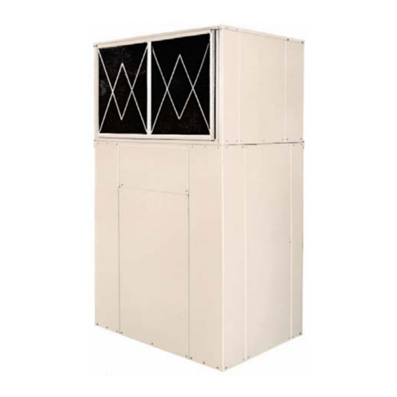
VERTICAL AIR COOLED AIR CONDITIONERS
Self Contained (ACVZ, ACVBZ series)
& Split Systems (CCVZ/ECVZ, CCVBZ/ECVBZ series)
and maintenance instructions
Self Contained
Split, outdoor sectio
Split, indoor section
Nom inal cooling capacity
Self Containe
Split, outdoor section
Split, indoor sectio
Nom inal cooling capacity
Nom inal heating capac ity
& AIR TO AIR HEAT PUMPS
Installation, operation
COOLING MODELS
ACVZ
351 401 501 701 721 751 801 1001 1002 1201 1402 1502 2002 2302 2402
CCVZ
351 401 501 701 721 751 801 1001 1002 1201 1402 1502 2002 2302 2402
ECVZ
351 401 501 701 721 751 801 1001 1002 1201 1402 1502 2002 2302 2402
k W
10,0 11,5 14,9 18.7 19,5 22,2 23,4 30,0 29,8 36,0 37,4 44,4 60,0 67,0 72,0
HEAT PUMP MODELS
ACVBZ 351 401 501 701 721 751 801 1001 1201 1402 1502 1602 2002 2302 2402
CCVBZ 351 401 501 701 721 751 801 1001 1201 1402 1502 1602 2002 2302 2402
ECVBZ 351 401 501 701 721 751 801 1001 1201 1402 1502 1602 2002 2302 2402
k W
9,8 11,5 14,7 18.6 19,4 22,1 23,2 29,7 35,0 37,2 44,2 46,4 59,4 66,0 70,0
k W
10,4 12,7 15,6 19.6 20,6 23,5 24,4 31,7 37,0 39,2 46,6 48,8 63,4 70,0 74,0
IOM 3.2 / HE OCT 2002
HITECSA
ISO 9002
EN29002
UNE66902
Advertisement
Table of Contents

Related Manuals for Hitecsa ECVBZ Series


Summary of Contents for Hitecsa ECVBZ Series
- Page 1 IOM 3.2 / HE OCT 2002 HITECSA VERTICAL AIR COOLED AIR CONDITIONERS & AIR TO AIR HEAT PUMPS Self Contained (ACVZ, ACVBZ series) & Split Systems (CCVZ/ECVZ, CCVBZ/ECVBZ series) Installation, operation and maintenance instructions COOLING MODELS Self Contained ACVZ 351 401 501 701 721 751 801 1001 1002 1201 1402 1502 2002 2302 2402...
-
Page 2: Physical And Electrical Data
PHYSICAL AND ELECTRICAL DATA COOLING MODELS MODEL ACVZ 1001 1002 1201 1402 1502 2002 2302 2402 Power supply + 400/3/50 Unit Operating Weight Refrigerant Charge 2x3,6 2x4,7 2x4,8 2x7,8 2x8,6 2x9,0 Control Circuit Voltage OUTDOOR SECTION CCVZ Operating Weight COMPRESSOR Type Reciprocating Scroll... -
Page 3: Heat Pump Models
PHYSICAL AND ELECTRICAL DATA HEAT PUMP MODELS MODEL ACVBZ 1001 1201 1402 1502 1602 2002 2302 2402 400/3/50 Power supply + Unit Operating Weight 1080 1115 1135 Refrigerant Charge 2x5,8 2x6,7 2x6,7 2x7,0 2x8,3 2x8,3 Control Circuit Voltage OUTDOOR SECTION CCVBZ Voltage 400-3-50... -
Page 4: Installation Location
GENERAL INSTALLATION LOCATION Check the following points: This manual reviews general rules which must be re- spected during the installation and maintenance of air 1. The construction must be able to support the unit conditioning systems. operating weight. 2. Allow sufficient space for servicing and air flow ac- Before starting the system installation read this cess around the outdoor units. -
Page 5: Air Ducts
3. Provide a trap properly sized for correct water evacu- ATTENTION: To avoid electrical shock, injury or ation (see Fig. 1). equipment damage, be sure that the ON-OFF power 4. Drain piping should be located below the drain con- switch is in OFF position. Field wiring must comply nection and should have inclination to assure proper with all local regulations and codes. - Page 6 RIGGING spreaders prevent 3. Never tip or roll the unit more damage to the panels and coils. than 15º. 2. Avoid violent movements of the 4. Check if all panels are in unit. correct location and are firmly fastened with the screws. Min.
- Page 7 RECOMMENDED SERVICE SPACE (mm) WEIGHT DISTRIBUTION WEIGHT DISTRIBUTION (kg) Self-contained units Outdoor units M O D E L M O D E L 3 51 3 51 4 01 4 01 5 01 5 01 1 02 7 01 7 01 1 28 7 21 7 21...
- Page 8 SPLIT SYSTEMS VERSION REFRIGERANT LINES REFRIGERANT LINES SELECTION CONNECTIONS AND When designing refrigerant lines you have to consider REFRIGERANT CHARGE different piping arrangements: Units are shipped from the factory with nitrogen LAYOUT ACCORDING TO FIGURE 2 charge and soldered piping connections. Piping con- nections should be made by qualified installer.
- Page 9 Suction / discharge line. Vertical pipe run - Fig. 3 For heat pump systems use a trap at the base of the vertical pipe run. There is no need for intermediate trap. For cooling only systems traps are not required. For heat pump systems keep veloc- ity in the vertical run of suction or discharge line more than 6 m/s.
-
Page 10: Unit Start-Up
LINE DIAMETER DIAMETER OF GAS LINES In the cooling operation suction line hold gas refrigerant and in the heat pump operation discharge line is also gas line. Line diameter is selected in the most unfavourable conditions. It is nec- essary to check for both cases. In the case of the layout shown on fig- ure 2 the suction line velocity will pro- duce the worse conditions and gas line... - Page 11 DEFROST (Heat pump systems) At low outdoor temperature during heating cycle and producing defrost by hot gas injection. depending on air humidity, frost will appear on the outdoor coil. It is necessary to remove the ice for proper During this cycle, the auxiliary electrical heating coil continuation of the heating cycle.
-
Page 12: Maintenance
MAINTENANCE It is advisable to make maintenance visits every 1000 necessary to make a leak test. If result is not satisfac- hours of the system operation, or every cooling sea- tory follow with gas tightness test using compressed son. nitrogen. It has to be performed by an experienced service technician. -
Page 13: Remote Control Operation
REMOTE CONTROL OPERATION CONTROL SYSTEM COOLING - Select "COOL" position with selector Adjust required room temperature with knob . If this temperature is below the effective room temperature The unit is controlled from a remote room thermostat. the compressor will operate after a time delay. Type of thermostat is indicated in the following table: HEATING - Select "HEAT."... -
Page 14: Operating Mode Selection
OPERATING MODE SELECTION: Heat pump systems: If this temperature is above the effective room temperature the compressor will oper- Cooling Heating ate after a time delay (or for two compressors models, Automatic OFF Disables controller if necessary the second compressor will be energized after the first one). -
Page 15: Start-Up Checklist
START-UP CHECK LIST Equipment sold by: ........... Start-up date: ............Installed by: .............. Site address: ................................Equipment type and serial number: ........................ELECTRICAL DATA Supply voltage Ph 1: ..... Volts Ph 2: ..... Volts Ph 3: ..... Volts Nominal voltage: ......... Volts % network voltage: ...... - Page 16 Subject to change without notice.
Need help?
Do you have a question about the ECVBZ Series and is the answer not in the manual?
Questions and answers