
Related Manuals for Geosense IPI-V-1


Summary of Contents for Geosense IPI-V-1
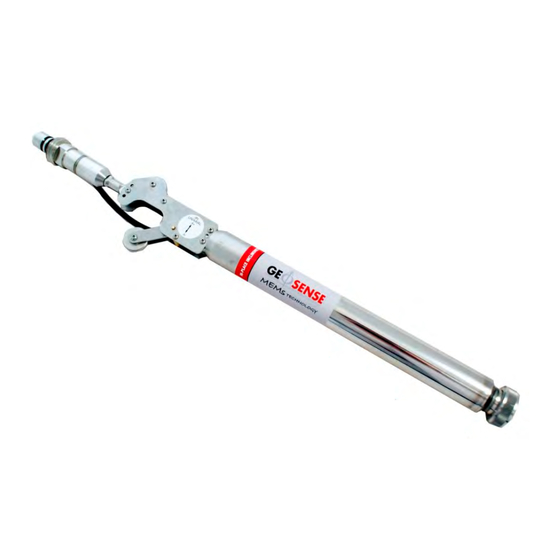
- Page 1 V1.0 September 2017 MEMS Digital Vertical In-Place Inclinometer...
-
Page 2: Table Of Contents
V1.0 September 2017 CONTENTS PAGE INTRODUCTION General Description Theory of operation Measurement of tilt CONFORMITY MARKINGS DELIVERY Packaging Handling Inspection Storage INSTALLATION Preparation for installation System components - extension rod Installation with extension rods System components - wire rope Installation with wire rope Wiring 5.6.1 Colour coding... -
Page 3: Introduction
Embankment stability and safety monitoring Stability of retaining walls Dam monitoring Horizontal pile testing Slope stability monitoring ® Particular features of Geosense IPI’s are:- Reliable long term performance. Ruggedness; suitable for demanding environments. Simple, cable free interconnection. High accuracy. Digital output, therefore insensitive to long cable lengths and joints ®... - Page 4 Digital signals are capable of long transmission distances without degradation. ® Each Geosense IPI has a unique identification number, thereby simplifying the interconnection using 4 wire digital protocols. ®...
-
Page 5: Theory Of Operation
Since they are digital, the cable from the IPI modules can be connected together in a ‘string’, thereby minimising the cables from each installation. ® In most cases, Geosense IPI’s are mechanically inter-connected using ‘Universal joints’ so as to maintain a physically connected profile of measurement. -
Page 6: Measurement Of Tilt
V1.0 September 2017 (Continued from page 5) 1.3 The measurement of tilt The A axis is the primary axis and the B axis is the secondary axis. Uni-axial IPI sensors only detect changes in the A axis. After their installation, the vertical profile of the inclinometer casing is established from the readings of individual IPI sensors. -
Page 7: Conformity
Declaration of Conformity ® ® We Geosense Ltd at above address declare under our sole responsibility that the Geosense products detailed below to which this declaration relates complies with protection requirements of the following harmonized EU Directives:- The Electromagnetic Compatibility Directive 2014/30/EU... -
Page 8: Markings
Digital MEMS In-place Inclinometer systems are labelled with the following information:- Manufacturers telephone number & website address Product group: MEMS Inclinometer system Product type: MEMS In-place inclinometer system Model: IPI-V-1, IPI-V-2, IPI-I-1, IPI-I-2, IPI-H-1, IPI-H-2 Range: +/- 15º Orientation: Uni-axial or biaxial Input supply: 8-15 Volts DC... -
Page 9: Delivery
V1.0 September 2017 4.0 DELIVERY ® This section should be read by all users of IPI’s manufactured by Geosense 4.1 Packaging ® Geosense IPI’s are packed for transportation to site. Packaging is suitably robust to allow normal handling by transportation companies. Inappropriate handling techniques may cause damage to the packaging and the enclosed equipment. -
Page 10: Storage
V1.0 September 2017 (Continued from page 9) 4.4 Storage All equipment should be stored in an environment that is protected from direct sunlight. It is recommended that cables be stored in a dry environment to prevent moisture migrating along inside them in the event of prolonged submersion of exposed conductors. -
Page 11: Installation
V1.0 September 2017 5.0 INSTALLATION ® This section of the manual is intended for all installers of Geosense IPI’s and is intended to provide guidance with respect to their installation. It must be remembered that no two installations will be the same and it is inevitable that some ‘fine tuning’... - Page 12 V1.0 September 2017 (Continued from page 11) Cable Cables should be marked with a unique identification system. Where multiple cables are to be grouped together along one route, markings should be repeated at regular intervals along the cable, so that in the event of cable damage, there may be a chance that the identification could be exposed and the cables re-joined.
-
Page 13: System Components - Extension Rod
V1.0 September 2017 System components - extension rod version Illustrated below are the typical components of a typical IPI installation 1 - TOP HANGER Used to suspend the complete IPI string. Placed on the top of the 70mm inclinometer casing INSTALLATION FORK - (not shown) Used to support the IPI string during installation. -
Page 14: Installation With Extension Rods
V1.0 September 2017 5.3 Installation with extension rods STEP 1 - Assemble the component parts required for a the installation. STEP 2 - Remove the BLACK end cap from the end of one of the rods. Note the locating socket on this ‘male’... - Page 15 V1.0 September 2017 (Continued from page 14) 5.3.Installation with extension rods contd…. Note the corresponding locating pin in the ‘Female’ end of the interconnection on the IPI sensor STEP 4 - Offer the two sides of the connector together, aligning the positions of the locating pin and socket STEP 5 - Push the two halves of the joint together until the threads meet...
- Page 16 V1.0 September 2017 (Continued from page 15) Geosense IPI’s always have the IPI module at the top of any extension rod 5.3 Installation with extension rods contd…. The bottom wheel assembly should always be installed first To reduce the installation time it all the rods and sensors can be pre-assembled.
- Page 17 V1.0 September 2017 (Continued from page 16) 5.3 Installation with extension rods contd…. 8. Remove the red end cap from the end of the extension rod that is going to be connected to the lowest sensor. STEP 8 - Connect the first extension rod to the bottom wheel assembly making sure to check the ‘pin - socket’...
- Page 18 V1.0 September 2017 (Continued from page 17) Consequently, the ‘sprung’ wheel should be located in the keyway in the inclinometer casing opposite to the direction of expected movement. 5.3 Installation with extension rods contd…. STEP 9 - Lower the wheel assembly into the inclinometer casing, taking care to orientate the wheels correctly.
- Page 19 V1.0 September 2017 (Continued from page 18) 5.3 Installation with extension rods contd…. STEP 12 - Remove the dust cap from the lower connector of the next extension rod and sensor assembly to be installed STEP 13 - Remove the top BLACK dust cap from the previously installed IPI sensor and carefully align the Check to ensure that all...
- Page 20 V1.0 September 2017 (Continued from page 19) lower the assemblies into the inclinometer casing ensuring the wheels are in the same keyways as the bottom wheel assembly Repeat steps 15 to 20 until all the IPI modules are connected. 5.3 Installation with extension rods Top hanger contd….
- Page 21 V1.0 September 2017 (Continued from page 20) 5.3 Installation with extension rods contd…. STEP 21 - with the assembly The top fly lead assembly is a universal component which acts as the top suspension adaptor and cable connector suitably and safely supported remove the spport tool STEP 22 - Loosen the safety rope and lower the assemblies into the inclinometer...
- Page 22 V1.0 September 2017 (Continued from page 21) 5.3 Installation with extension rods contd…. STEP 21 - Continue lowering the a assembly until the top IPI ASSEMBLIES SHOULD ALWAYS BE SUSPENDED NEVER REST THEM ON THE BOTTOM WHEEL ASSEMBLY hanger unit rests on the top the inclinometer casing (It is good practice to mark the position of the top hanger on the...
-
Page 23: System Components - Wire Rope
V1.0 September 2017 System components - wire rope Illustrated below are the typical components of a typical wire rope IPI installation 1 - TOP HANGER Used to suspend the complete IPI string. Placed on the top of the 70mm inclinometer casing INSTALLATION FORK - (not shown) Used to support the IPI string during installation. -
Page 24: Installation With Wire Rope
V1.0 September 2017 5.5 Installation with wire rope STEP 1 - Assemble the component parts required for a the installation. STEP 2 - Identify which sensor is to be located at the base of the installation and remove the plug . STEP 3 - Remove the BLACK cap from the end of the bottom wheel/termination assembly... - Page 25 V1.0 September 2017 5.5 Installation with wire rope contd... Note the corresponding locating pin in the ‘Female’ end of the interconnection on the IPI sensor STEP 4 - Offer the male connection on the bottom wheel assembly to the female connection on the bottom sensor aligning the positions of the locating pin and socket.
- Page 26 V1.0 September 2017 5.5 Installation with wire rope contd... STEP 7 - Connect a length of safety rope to the bottom wheel assembly using the loop provided. Shown here is the rope passing through the plastic cable clip, for neatness, but this is not essential.
- Page 27 V1.0 September 2017 5.5 Installation with wire rope contd... STEP 10 - once the top of the assembly nears the top of the casing place the installation fork into the slots on the top of the connector to support the assembly ready for the next part of the installation STEP 11 - identify the next IPI sensor to be installed and remove the...
- Page 28 V1.0 September 2017 5.5 Installation wire rope contd... STEP 13 - tighten the two connectors together as in STEP 6 STEP 14 - connect the Rapid Link on one end of an intermediate wire rope support onto the top of the IPI sensor STEP 15 - lift to remove the installation fork and lower the assembly into the casing...
- Page 29 V1.0 September 2017 5.5 Installation with wire rope contd... STEP 16 - continue to lower the assembly into the casing REPEAT FOR ALL SENSORS STEP 17 - identify the top IPI sensor and connect one end of the top support wire rope using the Rapid Link STEP 18 - attach the other end of the top support wire to the top collar...
- Page 30 V1.0 September 2017 5.5 Installation with wire rope contd... STEP 19 - lower the assembly gently into the casing STEP 20 - once the top collar hanger rests on the top of the casing secure the support rope to its final location. IPI ASSEMBLIES SHOULD ALWAYS BE SUSPENDED NEVER REST THEM ON THE...
-
Page 31: Wiring
5.6.2 RS-485 to RS-232 Interface Depending on what type of readout (Windows tablet) or datalogger (e.g. Campbell Scientific) being used with the Geosense IPI an RS-485 to RS-232 Interface module may be required (see below). Various types of screened cables are available and the Interface has been designed to be used with DIN 47100 colour coding. -
Page 32: Wi-Sos 480 Digital Node
5.6 Wiring contd... 5.6.3 WI-SOS 480 Digital Node ® The Geosense In-Place Inclinometer (IPI) is fully compatible with the WI-SOS 480 Digital Node and is wired as shown below. (Please refer to the WI-SOS 480 manual for further details on configuration) -
Page 33: Windows Tablet
V1.0 September 2017 5.6 Wiring contd... 5.6.4 Windows Tablet ® The Geosense In-Place Inclinometer (IPI) can be read directly with a Windows Tablet such as the Linx shown below. The accessories that will be needed in addition are:- RS-485 to RS-232 Interface •... -
Page 34: Data Handling
IPI’s are excited and interrogated using RS-485 digital protocols. A digital interface unit is required to connect from a standard RS-232C connection (as ® used by dataloggers, tablets, PCs, Notebooks or similar). Geosense supply a dedicated RS232 to RS485 interface to be used with a Windows based device. - Page 35 V1.0 September 2017 C. Connect the USB cable from the Digital Interface to the machine running the software D. If Windows does not automatically install the device drivers for the Digital Interface, it may be necessary to perform a Windows Update to locate the drivers from the internet E.
- Page 36 V1.0 September 2017 (Continued from page 35) H. Select the preferred Temperature Units from the drop down list - Celsius, Fahrenheit or Kelvin J. Enter the Serial number of the sensor to be interrogated and press the ‘Connect to Sensor’ button K.
-
Page 37: Data Reduction
V1.0 September 2017 6.2 Data reduction The output from the sensor must be compared with its calibration sheet to calculate the amount of tilt. Each IPI sensor has a unique calibration sheet and the simple calculation converts the sensor output to engineering units, commonly degrees or mm/metre. The readings generated by Digital IPIs are in ‘Sine of the Angle’. - Page 38 V1.0 September 2017 6.2 Data reduction contd... Readings from the IPI will be in sine of the angle Sine of angle to degrees –1 –1 ∆Y = (Base reading Sin ) - (Current reading Sin –1 –1 Example ∆Y = (0.08716 Sin ) - (0.17365 Sin ∆Y = (5.000) - (10.000) = - 5.000º...
-
Page 39: Calibration Certificate
V1.0 September 2017 6.3 Calibration certificate... -
Page 40: Temperature Considerations
V1.0 September 2017 6.4 Temperature Considerations ® Geosense has carried out significant research into temperature effects on the IPI and has found that the thermal effects are very small. Where the IPI is installed in an inclinometer access tube in a borehole or other subsurface structure, there is usually little variation in temperature, so thermal effects will be small and corrections will not be necessary. -
Page 41: Maintenance
V1.0 September 2017 7.0 MAINTENANCE ® The Geosense IPI is a maintenance free device for most applications. This is because it is intended for sub-surface installation and would normally be suspended in access tubes within boreholes or attached to structures. - Page 42 V1.0 September 2017 8.0 TROUBLESHOOTING contd…. Fault finding assistance for the cabling :- Using a Resistance meter or Electrical Multi-meter set to measure resistance, check the resistance between each conductor and between each conductor and the drain wire or screen. There should be a VERY high, or infinite electrical resistance between the conductors and the drain or screen (a value in MΩ’s is acceptable).
-
Page 43: Specification
V1.0 September 2017 9.0 SPECIFICATION MODELS Orientation Range Uniaxial Biaxial Vertical ±15° from vertical IPI-V-1 IPI-V-2 Inclined ±15° from 45° IPI-I-1 IPI-I-2 Horizontal ±15° from horizontal IPI-H-1 IPI-H-2 PERFORMANCE Accuracy ±0.004°, ±13.5 arc sec, ±0.065 mm/m, ±0.0125% FS Resolution 0.0005°, 2 arc sec, 0.01 mm/m, 0.0017% FS Repeatability ±0.002°, ±7.2 arc sec, ±... -
Page 44: Return Of Goods
11.2 Packaging and Carriage All used goods shipped to the factory must be sealed inside a clean plastic bag and ® packed in a suitable carton. If the original packaging is not available, Geosense should ® be contacted for advice. Geosense will not be responsible for damage resulting from inadequate returns packaging or contamination under any circumstances. -
Page 45: Limited Warranty
V1.0 September 2017 12.0 LIMITED WARRANTY The manufacturer, (Geosense Ltd), warrants the MEMS Digital In-Place Inclinometer manufactured by it, under normal use and service, to be free from defects in material and workmanship under the following terms and conditions:- ®... - Page 46 V1.0 September 2017...
Need help?
Do you have a question about the IPI-V-1 and is the answer not in the manual?
Questions and answers