Table of Contents
Advertisement
Quick Links
Advertisement
Table of Contents

Related Manuals for Geosense VWCM-4000


Summary of Contents for Geosense VWCM-4000
- Page 1 V 1.3 Feb 19 VWCM-4000 CRACK METER...
- Page 2 V 1.3 Feb 19...
-
Page 3: Table Of Contents
V 1.3 Feb 19 CONTENTS Page INTRODUCTION General description Theory of operation CONFORMITY MARKINGS DELIVERY Packaging Handling Inspection Storage INSTALLATION Getting started Preliminary tests Setting distances Installation - using re-bar anchors Installation - using mechanical anchors Installation - using welded anchors DATA HANDLING Taking readings 6.1.1... -
Page 4: Introduction
V 1.3 Feb 19 1.0 INTRODUCTION This manual is intended for all users of VWCM-4000 Crack Meters manufactured by ® Geosense and provides information on their installation, operation and maintenance. It is VITAL that personnel responsible for the installation and use of the VW Crack Meter READ and UNDERSTAND the manual, prior to working with the equipment. -
Page 5: Theory Of Operation
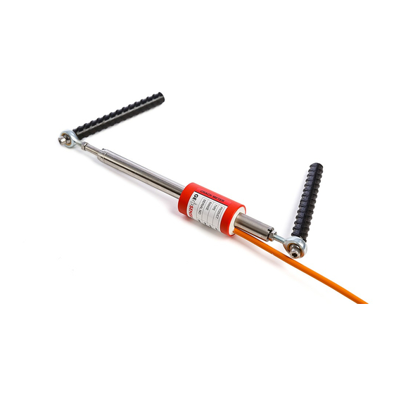
® The Geosense VWCM-4000 Crack Meter is an stainless steel instrument that contains a VW transducer that is connected to a Calibrated Spring which is in turn connected to an extending shaft. The ends of the instrument are connected to either side of a crack or joint so that, as structural movement occurs, the shaft is moved within the housing. -
Page 6: Conformity
Rougham, Bury St Edmunds Email: info@geosense.co.uk Declaration of Conformity We Geosense Ltd at above address declare under our sole responsibility that the Geosense products detailed below to which this declaration relates complies with protection requirements of the following harmonized EU Directives,... -
Page 7: Markings
V 1.3 Feb 19 3.0 MARKINGS Geosense VW Crack Meter are labelled with the following information:- Manufacturers name & contact details Product name Product Type Operating Range Serial number Electrical Input & Output details CE mark... -
Page 8: Delivery
V 1.3 Feb 19 4.0 DELIVERY This section should be read by all users of VWCM-4000 Crack Meters manufactured ® by Geosense 4.1 Packaging VWCM-4000 Crack Meters are packed for transportation to site. Packaging is suitably robust to allow normal handling by transportation companies. Inappropriate handling techniques may cause damage to the packaging and the enclosed equipment. -
Page 9: Storage
V 1.3 Feb 19 4.4 Storage All equipment should be stored in an environment that is protected from direct sunlight. It is recommended that cables be stored in a dry environment to prevent moisture migrating along inside them in the event of prolonged submersion of exposed conductors. -
Page 10: Installation
V 1.3 Feb 19 5.0 INSTALLATION This section of the manual is intended for all users of VWCM-4000 Crack Meters ® manufactured by Geosense and is intended to provide guidance with respect to their installation. It must be remembered that no two installations will be the same and it is inevitable that some ‘fine tuning’... -
Page 11: Preliminary Tests
/1000 ( Linear Digits ) units, since the calibration sheet is presented in Hertz /1000 units. The Geosense Readout model VW200 displays the readings in ‘Period’. The RST readout / logger unit Model Number VW2106 displays the readings in Linear Digits. See Section 6 of this manual for more information about units and conversion routines. - Page 12 V 1.3 Feb 19 5.3 Anchor spacing distance The positioning of the fixing anchors (spacing distance) will depend on the range of the crack meter and whether extension or compression is to be monitored. If this is unknown gauges are typically set to mid-range. The Table below shows the suggested anchor spacing distances for various operating ranges and measurement configurations.
-
Page 13: Installation - Using Re-Bar Anchors
V 1.3 Feb 19 5.4 Installation - using Re-bar anchors INSTALLATION TEMPLATE It is recommended to make and use a ‘site specific’ spacing template for the following reasons:- Maintains a consistent setting distance between the anchors • Makes marking of drill holes easier •... - Page 14 V 1.3 Feb 19 5.4 Installation - using Re-bar anchors contd... 7. Cleaning out the drill holes BE SURE NO ELECTRICAL CABLES OR OTHER SERVICES ARE DIRECTLY BELOW SURFACE TO BE DRILLED before inserting bonding resin is essential . A small brush is a good tool for cleaning out the loose debris and the bicycle pump is good for blowing out the dust so that the resin can adhere well to the inner walls of...
- Page 15 V 1.3 Feb 19 5.4 Installation - using Re-bar anchors contd... SELECT A NON-SHRINKING RIGID RESIN SUITABLE FOR THE MATERIAL INTO WHICH ANCHORS ARE BEING PLACED 10. Thoroughly mix an adequate amount of resin and fill the anchor holes. Where a resin cartridge is being used, insert the cartridge nozzle into the base of the holes and fill from the base upwards.
- Page 16 V 1.3 Feb 19 5.4 Installation - using Re-bar anchors contd... 13. Fix the M6 bolt through the Rose joint on the transducer end of the crack meter and into the rebar anchor. 14. Fit the M5 bolt through the Rose joint on the shaft end of the gauge and carefully extend the shaft.
- Page 17 V 1.3 Feb 19 5.4 Installation - using Re-bar anchors contd... ensuring the alignment pins engage with the slots on the housing tube. Tighten the locking nut to ensure that the rose joint is tight. 18. Re-fix the crack meter to the anchor and tighten the screw using the Allen key.
-
Page 18: Installation - Using Mechanical Anchors
V 1.3 Feb 19 5.5 Installation - using mechanical type anchors INSTALLATION TEMPLATE It is recommended to make and use a ‘site specific’ spacing template for the following reasons:- Maintains a consistent setting distance between the anchors • Makes marking of drill holes easier •... - Page 19 V 1.3 Feb 19 5.5 Installation - using mechanical type anchors - cont... 5. Clean out the drill hole to ensure it is free from dust. A bicycle pump is useful here. BE SURE NO ELECTRICAL CABLES OR OTHER SERVICES ARE DIRECTLY BELOW SURFACE TO BE DRILLED 6.
- Page 20 V 1.3 Feb 19 5.5 Installation - using mechanical type anchors - cont... 8. Fit both the mounting blocks to the anchors. Remember that one end has a larger and one a smaller threaded crack meter mounting. Use the second nut on the fixing to ‘lock’ the mounting block onto the anchor.
- Page 21 V 1.3 Feb 19 5.5 Installation - using mechanical type anchors - cont... 11. Tighten the bolt using the 5mm Allen key ( use a spanner on the locking nut as a tightening reaction ) 12. Check that smaller Rose joint is screwed into the other end of the Crack meter.
- Page 22 V 1.3 Feb 19 5.5 Installation - using mechanical type anchors - cont... DO NOT ROTATE THE SHAFT 15. When the reading is correct remove the fixing and carefully allow the gauge to close, ensuring the alignment pins engage with the slots on the housing tube.
-
Page 23: Installation - Using Welded Anchors
V 1.3 Feb 19 5.6 Installation - using Welded anchors INSTALLATION TEMPLATE It is recommended to make and use a ‘site specific’ spacing template for the following reasons:- Makes marking of mounting positions easier • Can be used to support the anchor blocks during welding •... - Page 24 V 1.3 Feb 19 5.6 Installation - using Welded anchors - cont…. attached to the Crack meter by checking that it fully tightened to its locking nut. 5. Fit the larger end of the crack meter ( sensor end ) to its mounting, using the M6 bolt through the Rose joint, and tighten the Allen screw.
- Page 25 V 1.3 Feb 19 5.6 Installation - using Welded anchors - cont…. crack meter. To adjust, undo M5 bolt and carefully remove Rose joint from the anchor. Ensure that the Rose joint locking nut is loose and turn the Rose joint clockwise to lower the crack meter readings and anticlockwise to raise the readings.
-
Page 26: Data Handling
A number of data loggers are available to automatically excite, interrogate and record the reading from Vibrating Wire instruments. These include devices manufactured and supplied by Geosense in both single and multi-channel configurations, as well as equipment manufactured by other suppliers. - Page 27 For most Vibrating Wire sensors, these factors are unique and are detailed on the sensor calibration sheet. A unique calibration sheet is supplied with each Geosense VW crack Meter. An example of the calibration sheet is shown on page 39.
- Page 28 The instrument calibration sheet similar to the example on page 31 of this manual includes the following information: Model This refers to the Geosense model number. Serial This is a unique sensor identification number that can be found on the body of the crack meter and, for long cables, at the end of the cable.
- Page 29 V 1.3 Feb 19 (Continued from page 28) Lin. Error % FSO Non Linearity expressed as a percentage of the crack meters Full Scale. Poly. Error % FSO Non Linearity expressed as a percentage of the crack meters Full Scale. Deviation Non Linearity expressed in Digits (Hz /1000)
-
Page 30: Temperature Considerations
6.3 Temperature Considerations ® Geosense VWCM-4000 Crack Meters include temperature sensors. Where a crack meter are installed in a zone where its temperature is likely to fluctuate significantly, records of temperature data should be recorded. This can then be used to assess any temperature effects on the crack meter readings and on the structure being monitored . -
Page 31: Thermistor Linearization
V 1.3 Feb 19 6.3.1Thermistor Linearization USING STEINHART & HART LOG Thermistor Type. YSI 44005, Dale 1C 3001 B3, Alpha 13A3001-B3 Resistance/ temperature equation:- T= (1 / (A + B (LnR) + C(LnR) )) –273.2 Where:- T = Temperature in degrees Centigrade LnR= Natural log of Thermistor resistance. -
Page 32: Maintenance
V 1.3 Feb 19 MAINTENANCE The VWCM-4000 Crack Meter is a maintenance free device for most applications. This is because it is intended for installation in areas that may normally be inaccessible. Where accessible, the primary maintenance issue would be to ensure that it is free from the build up of debris and dust that may affect its performance. - Page 33 V 1.3 Feb 19 8.0 TROUBLESHOOTING - cont.
-
Page 34: Specification
V 1.3 Feb 19 9.0 SPECIFICATION VWCM-4000 Crack Meter Range 5, 12.5, 25, 50, 100, 150, 200, 300, 500mm Resolution <0.025% FS Accuracy ±0.1 to ±0.5% FS Non-linearity <0.5% FS Frequency range 1650-2700 Hz Nominal zero value 1850 Hz Body material... -
Page 35: Spare Parts
V 1.3 Feb 19 10.0 SPARE PARTS As a VWCM-4000 Crack Meter is a sealed unit, it is neither serviceable nor does it contain any replaceable parts. Civil engineering sites are hazardous environments and instrument cables can be easily damaged if they are not adequately protected. Geosense can therefore provide the following parts that may be required to effect repairs to instrument cables: PU coated 4 Core cable with foil shield and copper drain. -
Page 36: Return Of Goods
11.2 Chargeable Service or Repairs Inspection & estimate It is the policy of Geosense Ltd that an estimate is provided to the customer prior to any repair being carried out. A set charge for inspecting the equipment and providing an estimate is also chargeable. -
Page 37: Limited Warranty
Sufficient site data has been provided to Geosense Ltd by the purchaser as regards the nature of the installation to allow Geosense Ltd to select the correct type and range of VWCM-4000 Cracks Meters and other component parts. - Page 38 V 1.3 Feb 19 NOTES:...
- Page 39 V 1.3 Feb 19...
Need help?
Do you have a question about the VWCM-4000 and is the answer not in the manual?
Questions and answers