Table of Contents
Advertisement
Quick Links
Advertisement
Table of Contents
Troubleshooting

Subscribe to Our Youtube Channel
Related Manuals for Geosense WI-SOS 480


Summary of Contents for Geosense WI-SOS 480
- Page 1 Instruction Manual WI-SOS 480 LS-G6 Laser Node V1.0...
-
Page 2: Table Of Contents
CONTENTS Overview of the Laser node Equipment provided Laser node installation Supports Fixed mounting for vertical surfaces Fixed mounting for horizontal surfaces Adjustable mounting plate Swivel mounting bracket Vertical mounting plate (pole mounting) Mounting the Laser node Mounting the Laser node on a swivel mounting bracket Mounting the Laser node on an adjustable mounting bracket Powering the laser node Laser node configuration... -
Page 3: Overview Of The Laser Node
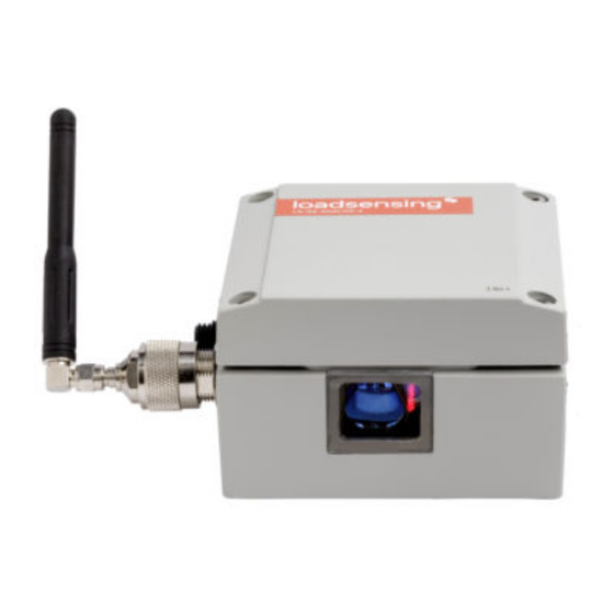
Overview of the Laser node This user guide explains the basic procedure for configuring and making operational the WI-SOS 480 LS-G6-Laser Node. Further technical description is available in the datasheets. The WI-SOS 480 LS-G6-Laser Node is a low-power long-range wireless datalogger and distance meter in a single compact box. - Page 4 5. Laser module case 6. Connector male RP N to RP - SMA male and aerial with RP - SMA male See the labels in the photos below for the position of each component. Laser node and its labelled component parts Antenna with N-connector...
-
Page 5: Laser Node Installation
Laser node installation The first task of getting your WI-SOS 480 LS-G6-Laser Node up and running on your site is to install it. There are three major factors to consider when installing the Laser node: the various supports you might use, the mounting of the Laser node, and powering the Laser node once it is installed. We discuss each of these three here. -
Page 6: Fixed Mounting For Vertical Surfaces
Fixed mounting for vertical surfaces The fixed mounting does not allow any movement. It is possible to use the same fixed mounting brackets and plates compatible with the WI-SOS 480 Wireless Tiltmeter. Vertical mounting plate (aluminium). Wall mounting. (Anchor bolts are not included) In this case, the laser beam is perpendicular to the vertical surface plane. -
Page 7: Adjustable Mounting Plate
In this case, the laser beam is parallel to the surface plane. Adjustable mounting plate For use on vertical surfaces, this support allows limited rotation in two axis with respect to the reference surface. It can be fixed to the surface with the same bolts as the fixed mounting plate. This support is proper for fine aiming of the laser beam. -
Page 8: Swivel Mounting Bracket
Adjustable mounting plate Swivel mounting bracket The swivel mounting bracket allows swivelling around the vertical axis (+/- 90 ) and a minor rotation ° ). It can be mounted on a wall or on a convergence bolt with ⅜” of the enclosure on the plate (+/- 3 °... - Page 9 Swivel mounting bracket Swivel mounting bracket, exploded diagram...
-
Page 10: Vertical Mounting Plate (Pole Mounting)
Vertical mounting plate (pole mounting) In the vertical mounting configuration, the Laser node can be mounted on a pole using metallic supports. The installation of the pole and its stability will be critical for the reliability of the readings. Depending on the installation, a pole can be more sensitive to deformation caused by environmental loads, such as wind, rain, snow, groundwater, or frost, than other structures. -
Page 11: Mounting The Laser Node
Mounting the Laser node See the images below for mounting the Laser node on a swivel mounting bracket and an adjustable mounting plate. The process is the same for installing the tiltmeter node on a fixed vertical bracket, so we have omitted images for that process. Mounting the Laser node on a swivel mounting bracket Drill the surface, place the anchor on the wall Adjust the upper bolt to fix the swivel support... -
Page 12: Mounting The Laser Node On An Adjustable Mounting Bracket
Mounting the Laser node on an adjustable mounting bracket Take off the lateral plate from the adjustable Insert the bolts provided inside the holes of the support by unscrewing the bolts. plate. Turn the four screws inside the device. Drill the three holes on the wall following the instruction and screw the four bolts onto the rectangular plate. -
Page 13: Powering The Laser Node
Powering the laser node The WI-SOS 480 Laser Distance Meter Node is shipped closed and may not have batteries installed. In order to initialise it, you should follow these steps: 1. Open the laser node (using a 2.5 mm Allen wrench) 2. -
Page 14: Laser Node Configuration
Connect your device to the node using the USB-OTG cable (see Accessories list above). Make sure the node has the required batteries. The app will automatically launch and display the node’s basic information. See Wi-SOS 480 G-Log Android Application Manual V1.0.12... - Page 15 Node information If the node needs to be recovered for some reason, an error prompt will be displayed on the screen. Once the user clicks on OK, a warning message about firmware corruption will also be displayed. After that, a firmware update will be needed to recover the node.
-
Page 16: Step 2: Glog Main Menu
Firmware screens Step 2: GLog main menu 1) Node info: Basic information about the node, such as version, ID, and temperature 2) Sensors data: Access to real time sensor readings and downloaded data stored in the node 3) Node configuration: Access this menu to configure the node a) Change node ID: Optional. - Page 17 Laser pointing tool screens To start node configuration, go to Node configuration from the main menu and then Setup Wizard. Node configuration...
-
Page 18: Step 3: Sensors Data
Node configuration - Setup wizard Step 3: Sensors Data The Sensors data screen displays the current readings of the unit. Sensors data ● Distance in meters, Temperature in degrees Celsius, Signal Strength, and Gain results are displayed ● The node takes a new reading every time the Refresh button (top right) is clicked ●... - Page 19 ● MultiGW for Connectivity Suite Radio type Sampling rate also needs to be set. Several sampling rates are displayed on the screen, and their availability will depend on the Network Size. Choose the desired reading frequency from the drop- down menu. The highest possible sampling rate is limited by the network size and vice versa. Smaller networks can read up to every 30 seconds and frequency is progressively reduced on bigger networks.
-
Page 20: Radio Configuration Advanced Options
Sampling rate Select the correct Region of radio frequency that matches with the LoRa region regulations. For successful communication, the same region must be applied in the Gateway radio configuration. The Network size is the number of nodes. We strongly recommend initially setting it to the final number of nodes that the wireless network will have since this parameter determines the available sampling rates. -
Page 21: Step 5: Radio Signal Coverage Test
4. Remember that the GLog saves and maintains radio settings to simplify configuration of all the nodes in a network. To modify these settings, Radio must be enabled again 5. Correct configuration of these two parameters (network size and sensor sampling rate) is crucial to prevent data transmission collisions, which translates to data loss on the Gateway. - Page 22 Radio signal coverage When doing the Radio signal coverage test, the position of the Android device is saved (if you gave the app permission to access the GPS data) and a security token number identifies each test. If the Gateway and/or the Android device are not connected to the Internet during the test, the online test will fail and you will need to perform an Offline test.
-
Page 23: Step 6: Test Results Interpretation
SFs reach smaller distances. During the radio signal coverage test, the WI-SOS 480 LS-G6-Laser Node sends five or ten data packages at SF7 to SF12. The number of data packages that reach the Gateway can be viewed in the... -
Page 24: Safely Closing The Laser Node
This is a very important step to ensure water tightness and durability of the laser node. Close the cover by tightening the indicated 2 Nm torque. The WI-SOS 480 Laser Distance Meter Node has undergone watertightness testing by an external laboratory and is rated IP67 (One meter for 30 minutes) and IP68 for extended immersion (One meter for seven days). -
Page 25: Understanding Data
Note that box screws shouldn’t be torqued more than 2 Nm, even though they can support a maximum torque of 3.5 N.m. If the torque is exceeded, the Helicoil insert may be damaged. We do not recommend using electric drills or electric screwdrivers. Understanding data The Laser node reads and transmits four values: ●... -
Page 26: Deployment Recommendations
Deployment recommendations The signal can be influenced by several factors, such as type or nature of the target and weather conditions of the environment. The following is a list of common conditions and the recommendation to follow for Target and Environment when deploying the Laser node. -
Page 27: Environment
Environment Environment, luminity, dust, wind and in general any weather condition also affects the quality of the signal (Signal Strength). The following is a table with a list of typical conditions and how they affect it. Luminity Implication Cave Signal Strength not affected. Optimal scenario. Artificial light or natural light exposure Signal Strength is affected depending on the direction of the external light;... -
Page 28: Maintenance And Troubleshooting
Laser beam is between 512 and 350000 uV). Outside these values, the Laser will return an error. Geosense recommends that for deployment in severely dusty environments the Laser node be cleaned if the Signal Strength is lower than 2000 uV. - Page 29 Company: Avery Dennison ( http://graphics.averydennison.eu/ ) Series: Avery 500 Event Film Type: Avery 501 EM - (white, matt) The foil can be easily stuck to the surface of the relevant fixture designed according to your monitoring need. Below are listed different types of LEICA Disto target plates models. These are some examples suitable for the Laser node, but they have been designed for manual readings (to be added at the support and take some measurements).
- Page 30 GZM26 for measurements on poorly reflective surfaces. Two sided: grey side for shorter distances and brown side for longer GZM30 stick-on target plates for placing on ground markers An additional suitable target will be the one, considering the conditions exposed on the previous paragraphs, with a combination of a white target with black edges.
-
Page 31: Battery Lifespan And Data Storage
Battery lifespan and data storage The following table provides the battery lifespan indicated for two SAFT LSH14 batteries lifetime estimates are based on distance measurements in the range 10 to 20 m and a model following a Barcelona temperature profile. Bear in mind that consumption varies depending on the sampling rate and environmental conditions. -
Page 32: Data Acquisition
Data acquisition Data is stored in the laser node in comma-separated variable (CSV) files. These files are available to download using the Android GLog application. Both readings and Health files can be downloaded. For this purpose, an Android device must be connected to the node Mini USB port with a USB-OTG cable. -
Page 33: Troubleshooting
● Water ingress - the WI-SOS 480 LS-G6-Laser Node ingress protection is IP67 (1 m of water column for 30 minutes). The tiltmeters should never be submerged in water. Water damage to the internal components voids the warranty. -
Page 34: Technical Specifications
Geosense is not liable for damages or erroneous decisions caused by defective units, since it is only responsible for the warranty of the equipment. For further information regarding the warranty conditions and the RAN process please refer to the Sales and Condition terms. - Page 35 Box dimensions (WxLxH) 100 x 100 x 61 mm Overall dimensions 150 x 100 x 61 mm (excluding antenna) Operating Temperature (º) -10 to +50 Storage temperature (º) -25 to +70 Weather protection IP67 External antenna 100 mm length (including connector) External port MiniUSB port for configuration and data access.
- Page 36 For completeness, find below a list of favourable/unfavourable conditions for measuring: Favourable average measuring Materials with good reflecting characteristics, meaning conditions they reflect the Laser beam in a divergent (not mirrored!) manner Laser dot is brighter than the ambient light Operating within the allowable temperature range 14°...
-
Page 37: Faq
What is the temperature influence on the measurement? The change of temperature and weather conditions of the deployment can affect the measurements of the Laser Node. However, temperature influence is included on the accuracy of the sensor according to reading conditions. See the technical specifications from the sensor. For further information and real scenario data signal analysis regarding temperature and weather conditions please refer to “Laser node data analysis under different scenarios”... -
Page 38: Safety Instructions
Safety instructions Laser beams emitted by the node are Class 2 according to IEC60825-1: 2014 Radiation safety of Laser products. WARNING Looking directly into the Laser beam with optical aids (e.g. binocular, telescopes) can be hazardous. CAUTION Looking into the Laser beam may be hazardous to the eyes. -
Page 39: Laser Classification Certificate
Laser Classification Certificate...
Need help?
Do you have a question about the WI-SOS 480 and is the answer not in the manual?
Questions and answers