
Related Manuals for Geosense DRI-1000


Summary of Contents for Geosense DRI-1000
- Page 1 MEMS Digital Portable Horizontal Inclinometer (USB-C) From Serial DRI-1000...
-
Page 2: Table Of Contents
MEMS Digital Portable Horizontal Inclinometer (USB-C) V1.0 25/10/2024 TABLE OF CONTENTS VERSION CONTROL INTRODUCTION 2.1. ENERAL ESCRIPTION 2.2. HEORY OF PERATION 2.3. EASUREMENT OF NCLINATION CONFORMITY MARKINGS DELIVERY 5.1. ACKAGING 5.2. ANDLING 5.3. NSPECTION UNCTIONALITY HECK EADINGS 5.4. TORAGE INCLINOMTER CASING INSTALLATION THEORY 6.1. - Page 3 MEMS Digital Portable Horizontal Inclinometer (USB-C) V1.0 25/10/2024 12.2. ASD R EADOUT 12.3. EEL AND ABLE SPARE PARTS RETURN OF GOODS 14.1. ETURNS ROCEDURE iii. Chargeable Service or Repairs Warranty Claim 14.2. ACKAGING AND ARRIAGE 14.3. & S RANSPORT TORAGE LIMITED WARRANTY...
-
Page 4: Version Control
Oct 2024 2. INTRODUCTION This manual is intended for all users of the Horizontal Portable Inclinometer Systems manufactured by Geosense® and provides information on their operating principles, conventions, operation and maintenance. It is VITAL that all personnel responsible for the use of the Portable Inclinometer... -
Page 5: General Description
Analogue to a Digital signal, making it particularly suitable for the demanding environments of geotechnical and civil engineering applications. Geosense® Inclinometer probes carry ‘onboard’ calibration data so that probe / cable / reel / readout combinations are all interchangeable. Each element also has a unique serial number. -
Page 6: Theory Of Operation
Theory of Operation Special tubes, commonly referred to as Casing or Access Tubes, are installed into or fixed onto the structure or formation to be monitored. (see Geosense® Inclinometer Casing Installation Manual). Inclinometer casing is a specially machined ABS tube that has 4 equally spaced, parallel ‘keyways’... - Page 7 MEMS Digital Portable Horizontal Inclinometer (USB-C) V1.0 25/10/2024 The Geosense® Digital Horizontal Inclinometer Probe houses a pair of extremely sensitive Micro Electro-Mechanical System (MEMS) Tilt Sensors. In the Horizontal probe, the ‘A’ axis is mounted with its ‘Null’ or ‘Zero’ output at 0 degrees from horizontal.
-
Page 8: The Measurement Of Inclination
(see sketch) and another reading is taken. This process is repeated up the full length of the casing. To minimise the issue of ‘Human Error’, Geosense® has introduced the option of ‘Automatic Inclinometer Data Acquisition’ into its proprietary software. This utilises the... -
Page 9: Conformity
MEMS Digital Portable Horizontal Inclinometer (USB-C) V1.0 25/10/2024 3. CONFORMITY... - Page 10 V1.0 25/10/2024 47 CFR § 2.1077 Compliance Information Unique Identifier: Geosense Ltd “Portable Inclinometer” This device complies with part 15 of the FCC Rules. Operation is subject to the following two conditions: (1) This device may not cause harmful interference, and (2) this device must accept any interference received, including interference that may cause undesired operation.
-
Page 11: Markings
V1.0 25/10/2024 4. MARKINGS Figure 3: Geosense Inclinometer Probe Markings All Geosense® Digital MEMS Inclinometer systems are labelled with the following information and each component carries a unique identification serial number that is included on the labels. Product group: MEMS Inclinometer system •... -
Page 12: Delivery
MEMS Digital Portable Horizontal Inclinometer (USB-C) V1.0 25/10/2024 5. DELIVERY This section should be read by all users of equipment manufactured by Geosense®. 5.1. Packaging Geosense® Inclinometers are packed for transportation to site. Packaging is suitably robust to allow normal handling by transportation companies. Inappropriate handling techniques may cause damage to the packaging and the enclosed equipment. -
Page 13: Storage
6.1. Baseline Prior to any survey taking place, the appropriate Geosense® Inclinometer Casing will need to have been installed on site. The Geosense® Horizontal Inclinometer system can be used to measure the profile of the casing in relation to a presumed fixed point. -
Page 14: Zone Of Influence
6.3. Zone of Influence The Geosense® Horizontal Inclinometer measures absolute angle, however the system as a whole is relative when referring to a measurement of displacement over a profile. This means that movement (displacement as a result of heave or settlement) in the vertical plane must be measured in relation to a fixed end of the system. -
Page 15: Operational Modes
MEMS Digital Portable Horizontal Inclinometer (USB-C) V1.0 25/10/2024 6.4. Operational Modes The Geosense® Portable Horizontal Inclinometer is designed to be used on installations where either both ends, or only one end of the inclinometer casing is accessible. Installation where both ends are accessible Access End... - Page 16 V1.0 25/10/2024 Where one end is not accessible, Geosense® are able to supply a dead-end pully which allows for the rope to be looped back and to the operator. Figure 6: Dead-end pulley (pipe fittings may vary dependent on casing used)
-
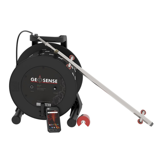
Page 17: Operation
25/10/2024 7. OPERATION This section of the manual is intended for all users of portable Geosense® inclinometer equipment and is intended to provide guidance with respect to its use. It must be remembered that no two installations will be the same and it is inevitable that some ‘fine tuning’... - Page 18 MEMS Digital Portable Horizontal Inclinometer (USB-C) V1.0 25/10/2024 Illustrated below (Figure 10: Inclinometer Components) are the components of the Geosense® Inclinometer and Readout System A. INCLINOMETER PROBE B. CABLE C. CABLE REEL/ASD CHARGER and CABLE D. ASD (ANDROID SMART DEVICE) and STYLUS E.
-
Page 19: System Component Descriptions
USB charger / power supply. 5) CABLE SUPPORTS For fitting into the top of all Geosense® Inclinometer casing (and the casing from most other manufactures), these are used to position the probe at a repeatable location within the casing. -
Page 20: Battery Charging
MEMS Digital Portable Horizontal Inclinometer (USB-C) V1.0 25/10/2024 7.3. Battery Charging Whilst the Reel and ASD have long battery lives, fully charging the equipment prior to visiting site is strongly recommended. As with most handheld equipment, the ASD can be easily charged using most USB chargers and power banks. - Page 21 MEMS Digital Portable Horizontal Inclinometer (USB-C) V1.0 25/10/2024 5) Remove the dust cap from the reel connector and fit the charger lead to the reel. (Figure 12: Charge Port - Inclinometer Reel) 6) Connect the charger to a mains electrical supply, switch it on and allow the readout to charge fully.
-
Page 22: Installing The Inclinometer Application On The Asd
7.4. Installing the Inclinometer Application on the ASD It is necessary to install the Geosense® software Inclinometer Application onto the ASD from the Google® Play Store. This will ensure the latest version is downloaded. For this it will be necessary to establish an ‘Identity’ with Google® and establish a connection to the internet. -
Page 23: System Assembly And Operation
MEMS Digital Portable Horizontal Inclinometer (USB-C) V1.0 25/10/2024 8. SYSTEM ASSEMBLY AND OPERATION 8.1. Assembling the System Most of the components of the Inclinometer Readout System are contained within the hard carry case. Only the cable, reel and its charger are housed within the soft case. 5) Remove the probe from the hard case and remove the black cable connector cap (Item F - Figure 10: Inclinometer Components) 6) Remove the cable reel from its case and remove the cable connector cover. - Page 24 MEMS Digital Portable Horizontal Inclinometer (USB-C) V1.0 25/10/2024 7) The Geosense® Horizontal Inclinometer has a connection at each end. This is so the probe can be rotated around the Z-axis to allow for the entry end to be changed between surveys.
- Page 25 MEMS Digital Portable Horizontal Inclinometer (USB-C) V1.0 25/10/2024 Machined mating guides must be aligned 8) Remove the Android ASD from the hard case and turn it on. (For detailed ASD specific instructions see Section 9 later in this manual).
- Page 26 10) On the ASD, check that the ‘Bluetooth’ symbol is showing in the top bar. (By default, it is set to turn on but if it is not, go to the ASD settings and turn it on). 11) Open the Geosense® Inclinometer Application ‘IncloPRO’. For detailed ‘App’ operating instructions, see Section 9.
- Page 27 MEMS Digital Portable Horizontal Inclinometer (USB-C) V1.0 25/10/2024 Figure 16: Paired Reels Screen 12) When using the App for the first time, it will be necessary to search for the Reel to carry out this pairing operation. Once paired, the ASD memorises the configuration.
- Page 28 MEMS Digital Portable Horizontal Inclinometer (USB-C) V1.0 25/10/2024 14) Tap the ‘Connect’ icon again if you wish to break the Bluetooth connection. It should return to an ‘all white’ colour. (If you are about to conduct a survey, leave the reel connected for now). 15) It is good practice to make sure the connection to the probe is good and the readings are relatively stable before the probe is inserted into the casing.
- Page 29 MEMS Digital Portable Horizontal Inclinometer (USB-C) V1.0 25/10/2024 16) Remove the cover from the inclinometer access tube if there is one. (A secure cover is strongly recommended to stop any foreign objects or animals entering the pipe work. Horizontal installations if not sealed can house rodents which can deposit nesting material that will block the access casing) Prior to any horizontal survey, the pull rope must have been installed within the inclinometer casing.
- Page 30 MEMS Digital Portable Horizontal Inclinometer (USB-C) V1.0 25/10/2024 II. If using a double ended installation, pull the rope through to the access end from the far end. Have someone stationed at the far end to make sure the loose end of the rope does not enter the installation. If you lose the end of the rope it may be difficult or impossible to recover.
- Page 31 MEMS Digital Portable Horizontal Inclinometer (USB-C) V1.0 25/10/2024 18) Release the brake screw on the side of the Cable Reel.
- Page 32 MEMS Digital Portable Horizontal Inclinometer (USB-C) V1.0 25/10/2024 19) Attach the dead-end pulley rope that is present inside of the inclinometer casing to the base end of the inclinometer probe. (For the first survey run, attach the eyelet to the end of the probe marked by 2 rings). Figure 19: Eyelet cap attached to second end of the probe, marked with 2 rings in later models (a 2 is shown in this model) It is CRITICAL that the pulley rope is FIRMLY ATTACHED...
- Page 33 MEMS Digital Portable Horizontal Inclinometer (USB-C) V1.0 25/10/2024 21) With tension applied to the “tension-end” of the rope, insert the Inclinometer probe into the casing in the vertical keyways. The fixed wheels must run at the base, with the sprung wheels gently slotted into the start of the access casing by hand.
- Page 34 MEMS Digital Portable Horizontal Inclinometer (USB-C) V1.0 25/10/2024 22) With tension applied to the “tension-end” of the rope, insert the Inclinometer probe into the casing, with the wheels engaged into the keyways. The sprung wheels will always be at the top, with the fixed set at the base. Figure 22: Inclinometer probe inserted into access casing.
- Page 35 MEMS Digital Portable Horizontal Inclinometer (USB-C) V1.0 25/10/2024 23) Once the probe has entered the casing fully, the probe should be pulled to the far end using the “tension-end” of the rope for the start of the survey. The survey should always be started from the far end. You must always start the survey from the same position (i.e.
- Page 36 MEMS Digital Portable Horizontal Inclinometer (USB-C) V1.0 25/10/2024 25) Using the rope and the cable, move the Inclinometer Probe to the far end of the casing, stopping when the ferrule marking the correct distance (depth if compared to the vertical system) is reached. Keep tension on the rope and cable at all times to avoid any slack.
- Page 37 MEMS Digital Portable Horizontal Inclinometer (USB-C) V1.0 25/10/2024 30) Once you reach the top/access end with the probe, the survey needs to be repeated, with the probe rotated 180 degrees around the Z-Axis. First Survey Orientation – 1 ring end connected to reel Second Survey Orientation –...
-
Page 38: Using Inclopro Software Application (Android)
MEMS Digital Portable Horizontal Inclinometer (USB-C) V1.0 25/10/2024 9. USING INCLOPRO SOFTWARE APPLICATION (ANDROID) 9.1. Recording a Survey The following steps detail how the readings can be taken with the IncloPRO Android application. Section 8. SYSTEM ASSEMBLY AND OPERATION must be followed for the operation of the survey. - Page 39 MEMS Digital Portable Horizontal Inclinometer (USB-C) V1.0 25/10/2024 I. If this is the first time a site has been visited for a survey, add the site/project that the Inclinometer survey is to be conducted on. i. Press the “+” symbol to the right and below the “Site List” and add the name of your site or project.
- Page 40 MEMS Digital Portable Horizontal Inclinometer (USB-C) V1.0 25/10/2024 Table 1: Borehole configuration settings Borehole Settings Description Borehole Name Text entry for the name of the borehole the survey is being conducted on Borehole Type The orientation of the survey. Different probes are required for different orientations First Reading Depth...
- Page 41 MEMS Digital Portable Horizontal Inclinometer (USB-C) V1.0 25/10/2024 4) When you are ready to begin the survey, select the “TAKE READINGS” button Figure 28: Take readings...
- Page 42 MEMS Digital Portable Horizontal Inclinometer (USB-C) V1.0 25/10/2024 5) With the probe inserted to the far end of the casing and at the first depth to be recorded, wait for the probe temperature to stabilise Figure 29: Probe stabilising...
- Page 43 MEMS Digital Portable Horizontal Inclinometer (USB-C) V1.0 25/10/2024 6) Once the probe has stabilised, you will be notified, and the survey can begin by pressing “Begin Survey”. Figure 30: Begin survey once the probe has stabilised...
- Page 44 MEMS Digital Portable Horizontal Inclinometer (USB-C) V1.0 25/10/2024 7) Once the survey begins, the first reading will show the live readings, the depth will be the furthest point from the access end, as set in the borehole information in the app. Make sure that the depth marked on the cable matches the depth shown in the app for each reading.
- Page 45 MEMS Digital Portable Horizontal Inclinometer (USB-C) V1.0 25/10/2024 1) Once the reading has been accepted, the app will move to the next depth (in this example, 7.5m as the probe is 0.5m long (as set in the borehole setup)). The probe will always move through three stages regardless of whether it is in manual or auto mode.
- Page 46 MEMS Digital Portable Horizontal Inclinometer (USB-C) V1.0 25/10/2024 5) At any time, the “QUICK DATA CHECK” can be activated, but “AUTO ACCEPT MODE” must be cancelled first. Figure 33: Quick data check screen 6) Use the “QUICK DATA CHECK” button to view the readings stored in memory, so far, at any point in the survey.
-
Page 47: Viewing Data
MEMS Digital Portable Horizontal Inclinometer (USB-C) V1.0 25/10/2024 If an error is detected, the depth can be changed to retake a reading from another position, by using the UP / DOWN buttons. 9.2. Viewing Data All completed surveys can be accessed from the “VIEW DATA” screen, located within the Borehole selection screen. - Page 48 MEMS Digital Portable Horizontal Inclinometer (USB-C) V1.0 25/10/2024 Table 2: View Data - Options available to the user View Settings Description Survey Data Table On screen display of the survey data (one survey selected at a time) Upload Selected Survey to FTP Creates an output file (in select output format) and uses FTP details entered into the settings menu to FTP the file for...
-
Page 49: Initial / Base Surveys
MEMS Digital Portable Horizontal Inclinometer (USB-C) V1.0 25/10/2024 9.3. Initial / Base Surveys It is common to carry out three sets of Initial Readings to form the Base Data file. Therefore, IncloPRO can use one, two or three sets of data to form the Base Data file, to which subsequent readings are compared. - Page 50 MEMS Digital Portable Horizontal Inclinometer (USB-C) V1.0 25/10/2024 To select data set(s) for use as the Base Data: 1) tap the “SET BASE SURVEYS” at the top of the Surveys list. 2) Select the suitable files and tap “OK”. This selection is stored on the ASD (Android Smart Device) so that it is not necessary to make this selection each time the data is viewed.
-
Page 51: Upload Selected Survey To Ftp
MEMS Digital Portable Horizontal Inclinometer (USB-C) V1.0 25/10/2024 9.4. Upload Selected Survey to FTP Where data is to be sent directly to a remote server, this option creates a file in the selected output format (CSV or RPP) and uses FTP details entered into the settings menu, to send the transmission. -
Page 52: Data Handling
If ‘.csv’ format is selected, the exported data file format is ASCII, making it commonly accessible via many software packages, and small in size. Geosense® has worked closely with ‘Deep Excavations Inc’, to enable PC based data handling via their ‘Site Master’ Inclinometer Data Presentation Software package. - Page 53 MEMS Digital Portable Horizontal Inclinometer (USB-C) V1.0 25/10/2024 Opened in a spreadsheet, each comma should be set to delineate a column so the header information would be presented as follows: Table 3: Manually entered borehole information – these details are commonly entered manually at the setup stages, and automatically populated when the data is exported.
- Page 54 MEMS Digital Portable Horizontal Inclinometer (USB-C) V1.0 25/10/2024 The following highlighted line of the file identifies the sequence of the variable values. Figure 36: Sequence of variable value columns Table 4: Variable value descriptions reading sequence (top of the tube = highest No.) DEPTH_METRES depth of a readings (cable marker value)
-
Page 55: Data Reduction
MEMS Digital Portable Horizontal Inclinometer (USB-C) V1.0 25/10/2024 The following figure (Figure 37: Format of raw .csv file format from export) shows the formatting of a typical raw .csv file export. ID, DEPTH_METRES, A_POSITIVE_SINX, B_POSITIVE_SINX, A_POSITIVE_MM, B_POSITIVE_MM, etc 19,0.5,0.0083666,0.0019453,4.1833,0.97265,-0.0083284,0.0216397,-4.1642,10.8198, 17.246,17,532 18,1,0.0083852,0.0019631,4.1926,0.98155,-0.0083313,0.021654,-4.16565,10.827,17.253,17.545 17,1.5,0.0074967,0.0019666,3.74835,0.9833,-0.0074857,0.0215836,-3.74285,10.7918,17.251,17.538 16,2,0.0075014,0.0019636,3.7507,0.9818,-0.0074974,0.0215763,-3.7487,10.7881,17.260,17.545... - Page 56 These are quite normal and the reason for recording both ‘+’ and ‘-’ values is to remove these differences. Geosense® calculate the Checksums using the following equation: Checksum A = (Reading A+) + (Reading A-)
- Page 57 MEMS Digital Portable Horizontal Inclinometer (USB-C) V1.0 25/10/2024 The position of the tube at a particular depth is represented by the accumulation of the Deviations at that depth. To calculate the total deviation from top to bottom use the following equation: Tot.
-
Page 58: Temperature Considerations
25/10/2024 10.3. Temperature Considerations Geosense® has carried out significant research into temperature effects on the Probe and its electronics and has found that the thermal effects are very small. However, at the beginning of a survey it is strongly recommended that the temperatures in the probe be allowed to ‘normalise’, (referred to as the stabilising period) thereby removing... -
Page 59: Maintenance
Silicon Grease to maintain ease of connection. Contact Geosense for information on how to service the connectors should they become dirty. A dirty connection will impede the function of the system, it is important to keep all connectors clean and free from debris at all times. -
Page 60: Storage
Possible Cause Remedy Difficulty connecting cable Keyways Align keyways aligned Lack of lubrication Damaged/bent pins Return to Geosense for repair Dirt/debris Clean with fresh water and remove all contaminants, then dry Threaded collars cross Do not force threaded parts threaded... - Page 61 MEMS Digital Portable Horizontal Inclinometer (USB-C) V1.0 25/10/2024 Wheelset does not return to fully extended position Presence of dirt / lack Clean with fresh water and dry, then lubricate with light of lubrication machine oil. problem persists, replace wheel sets* Wheels do not turn freely Presence of dirt / lack Clean with fresh water and...
-
Page 62: Asd Readout
Bluetooth devices items such as speakers that are linked to the same ASD Bluetooth fails Return Geosense connect despite using inspection the app The ASD freezes after extended periods of use Bluetooth connection Power cycle the reel and... -
Page 63: Reel And Cable
Possible Cause Remedy Reel will not turn on Flat battery Charge battery and check charger is functioning Fault with battery Replace battery – refer to Geosense support Cable becomes kinked/twisted Allowing probe Replace cable freefall incorrect deployment/recovery Do not allow probe to freefall... -
Page 64: Spare Parts
MEMS Digital Portable Horizontal Inclinometer (USB-C) V1.0 25/10/2024 13. SPARE PARTS Under normal use spare parts are not generally required for Geosense® Inclinometer Systems. However, the following items are available. It is strongly recommended that replacement service components be fitted by Geosense® or their qualified... -
Page 65: Return Of Goods
Inspection & Estimate It is the policy of Geosense® that an estimate is provided to the customer prior to any repair being carried out. A set fee for inspecting the equipment and providing an estimate is also chargeable. Inspection or repairs will not be undertaken without formal order coverage. -
Page 66: Packaging And Carriage
All used goods shipped to the factory must be sealed inside a clean plastic bag and packed in a suitable carton. If the original packaging is not available, Geosense® should be contacted for advice. Geosense® will not be responsible for damage resulting from inadequate returns packaging or contamination, under any circumstances. -
Page 67: Limited Warranty
Sufficient site data has been provided to Geosense® by the purchaser as regards the nature of the installation to allow Geosense® to select the correct type and range of MEMS Digital Inclinometer and other component parts. - Page 68 V1.0 25/10/2024 HEAD OFFICE NORTH AMERICA OFFICE Nova House 15 West 38th Street Rougham Industrial Estate Suite 632 Rougham, Bury St Edmunds New York Suffolk IP30 9ND NY 10018 England +44 (0)1359 270457 +1 518-920-3483 sales@geosense.com sales@geosense.com support@geosense.com support@geosense.com www.geosense.com...
Need help?
Do you have a question about the DRI-1000 and is the answer not in the manual?
Questions and answers