Advertisement
Quick Links
Advertisement

Related Manuals for Velleman VMA501


Summary of Contents for Velleman VMA501
- Page 1 VMA501 DIY STARTER KIT FOR ARDUINO ® USER MANUAL...
-
Page 2: Safety Instructions
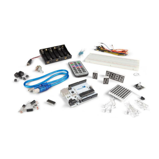
Nor Velleman nv nor its dealers can be held responsible for any damage (extraordinary, incidental or indirect) – of any nature (financial, physical…) arising from the possession, use or failure of this product. - Page 3 VMA501 Contents 1 x ATmega328 UNO DEVELOPMENT BOARD (VMA100) 15 x LED (different colors) 8 x 220 Ω resistor (RA220E0) 5 x 1k resistor (RA1K0) 5 x 10k resistor (RA10K0) 1 x 830 hole breadboard ...
-
Page 4: Operation
VMA501 USB interface 16 MHz clock reset button Atmel mega328p (DIL) digital I/O 7-12 VDC power input Atmel mega16U2 power and ground pins ICSP analogue input pins microcontroller ....................ATmega328 operating voltage ....................... 5 VDC input voltage (recommended) ................7-12 VDC input voltage (limits) ..................... - Page 5 VMA501 Chips have legs that come out of both sides and fit perfectly over the ravine. Since each leg on the IC is unique, we do not want both sides to be connected to each other. That is where the separation in the middle of the board comes in handy.
- Page 6 VMA501 Connection Programming Code Result After programming, you will see the LED connected to pin 10 blinking, with an interval of approximately one second. Congratulations, the experiment is now successfully completed! V. 02 – 05/04/2019 ©Velleman nv...
- Page 7 VMA501 PWM Gradational LED PWM (Pulse Width Modulation) is a technique used to encode analogue signal levels into digital ones. A computer cannot output analogue voltage but only digital voltage values. So, we will be using a high-resolution counter to encode a specific analogue signal level by modulating the duty cycle of PWM. The PWM signal is also digitalized because in any given moment, fully on DC power is either 5 V (on) of 0 V (off).
- Page 8 VMA501 Required Hardware 1 x variable resistor 1 x red M5 LED 1 x 220 Ω resistor 1 x breadboard jumper wires as needed Connection Programming Code V. 02 – 05/04/2019 ©Velleman nv...
- Page 9 VMA501 In this code, we are using the analogWrite (PWM interface, analogue value) function. We will read the analogue value of the potentiometer and assign the value to PWM port, so there will be corresponding change to the brightness of the LED. One final part will be displaying the analogue value on the screen. You can consider this as the analogue value reading project adding the PWM analogue value assigning part.
- Page 10 VMA501 Programming Code V. 02 – 05/04/2019 ©Velleman nv...
- Page 11 VMA501 The Active Buzzer An active buzzer is widely used on computers, printers, alarms, etc. as a sound-making element. It has an inner vibration source. Simply connect it with a 5 V power supply to make it buzz constantly. Required Hardware ...
- Page 12 VMA501 Connection Programming Code Result After programming, the buzzer should ring. V. 02 – 05/04/2019 ©Velleman nv...
- Page 13 VMA501 The Photosensitive Transistor A phototransistor is a transistor whose resistance varies according to different light strengths. It is based on the photoelectric effect of a semiconductor. If the incident light is intense, the resistance reduces; if the incident light is weak, the resistant increases. A phototransistor is commonly applied in the measurement of light, light control and photovoltaic conversion.
- Page 14 VMA501 Programming Code Result After programming, change the light strength around the phototransistor and observe the LED changing! The Flame Sensor A flame sensor (IR receiving diode) is specifically used on robots to find the fire source. This sensor is highly sensitive to flames.
- Page 15 VMA501 Connection Connect the negative to the 5 V pin and the positive to the resistor. Connect the other end of the resistor to GND. Connect one end of a jumper wire to a clip, which is electrically connected to sensor positive, the other end to the analogue pin.
- Page 16 VMA501 The LM35 Temperature Sensor The LM35 is a common and easy-to-use temperature sensor. It does not require other hardware, you just need an analogue port to make it work. The difficulty lies in compiling the code to convert the analogue value it reads to Celsius temperature.
- Page 17 VMA501 Programming Code Result After programming, open the monitoring window to see the current temperature. The Tilt Sensor Switch A tilt sensor will detect orientation and inclination. They are small, low power and easy-to-use. If used properly, they will not wear out. Their simplicity makes them popular for toys, gadgets and other appliances. They are referred to as mercury, tilt or rolling ball switches.
- Page 18 VMA501 Programming Code V. 02 – 05/04/2019 ©Velleman nv...
- Page 19 VMA501 7.10 The IR Receiver Infrared communication is a common, inexpensive and easy-to-use wireless communication technology. IR light is very similar to visible light, except that it has a slightly longer wavelength. This means that IR is undetectable to the human eye – perfect for wireless communication. Example: When you hit a button on your TV remote, an IR LED repeatedly turns on and off, 38000 times a second, to transmit information to an IR photo sensor on your TV.
- Page 20 VMA501 Programming Code 7.11 One-Digit Seven-Segment Display LED segment displays are common for displaying numerical information. They are widely applied on displays of ovens, washing machines, etc. the LED segment display is a semiconductor light-emitting device. Its basic unit is an LED (light-emitting diode). Segment displays can be divided into 7-segment and 8-segment displays.
- Page 21 VMA501 For the common anode display, connect the common anode (COM) to +5 V. When the cathode level of a certain segment is low, the segment is on; when the cathode level of a certain segment is high, the segment is off. For the common cathode display, connect the common cathode (COM) to GND.
- Page 22 VMA501 7.12 Four-Digit Seven-Segment Display V. 02 – 05/04/2019 ©Velleman nv...
- Page 23 VMA501 Connection Programming Code This is an example of how to drive a 7-segment LED display without the use of current limiting resistors. This technique is very common but requires some knowledge of electronics – you do run the risk of dumping too much current through the segments and burning out parts of the display.
- Page 24 VMA501 V. 02 – 05/04/2019 ©Velleman nv...
- Page 25 VMA501 V. 02 – 05/04/2019 ©Velleman nv...
- Page 26 VMA501 V. 02 – 05/04/2019 ©Velleman nv...
- Page 27 VMA501 V. 02 – 05/04/2019 ©Velleman nv...
- Page 28 VMA501 V. 02 – 05/04/2019 ©Velleman nv...
- Page 29 VMA501 7.13 8x8 LED Matrix With low-voltage scanning, LED dot-matrix displays have advantages such as power saving, long service life, low cost, high brightness, wide angle of view, long visual range, being waterproof… LED dot-matrix displays can meet the needs of different applications and thus have a broad development prospect.
- Page 30 © COPYRIGHT NOTICE The copyright to this manual is owned by Velleman nv. All worldwide rights reserved. No part of this manual may be copied, reproduced, translated or reduced to any electronic medium or otherwise without the prior written consent of the copyright holder.
- Page 31 • Velleman® can decide to replace an article with an equivalent article, or to refund the retail value totally or partially when the complaint is valid and a free repair or replacement of the article is impossible, or if the expenses are out of proportion.
Need help?
Do you have a question about the VMA501 and is the answer not in the manual?
Questions and answers
Existe o manual em português