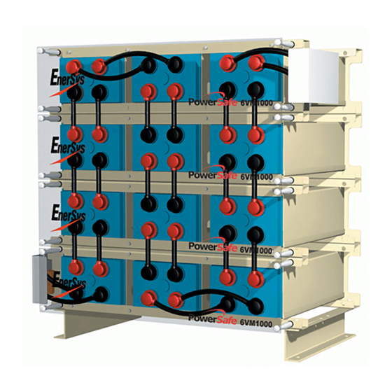
EnerSys PowerSafe VM Series Installation, Operation And Maintenance Manual
Hide thumbs
Also See for PowerSafe VM Series:
Advertisement
Advertisement
Table of Contents

Summary of Contents for EnerSys PowerSafe VM Series
- Page 1 BATTERY INSTALLATION, OPERATION AND MAINTENANCE MANUAL RESERVE POWER...
- Page 2 General Information 1. General Information IMPORTANT NOTE - IT IS MOST IMPORTANT TO READ AND FULLY UNDERSTAND THESE PowerSafe VM is a range of valve regulated ® INSTRUCTIONS BEFORE COMMENCING THE Safety Precautions sealed lead-acid batteries. The utilisation of gas UNPACKING AND INSTALLATION OF THE recombination technology ensures that, in normal BATTERY.
-
Page 3: Technical Specifications
EnerSys representative. EnerSys is not responsible for damage or missing If the cells are to be stored at high temperatures for prolonged periods you items not reported as above. The terminal voltage of each cell should be should consult your EnerSys representative for further advice on freshening checked to ensure that none are below 2.12 volts. - Page 4 7. Unpacking and Module Assembly e) take one of the two lifting strap/hook assemblies provided and attach it to a module. DO NOT USE THE HOLE IN THE SHORT SIDE OF THE U CHANNEL - USE ONLY THE HOLE DEPICTED IN FIG 3 . WARNING - THESE BATTERIES ARE HEAVY.
-
Page 5: Electrical Connections
i) repeat E, F and G. 8.1 Inter-tier and inter-row Connections. j) attach the two lifting strap/hook assemblies provided to the module and a) before despatch from the factory each individual cell terminal is cleaned using the lifting device position the module on top of the first and bolt and coated with a layer of non-oxide grease. - Page 6 a) fit the inner-shield to the module. The assembly of the battery is now completed to the stage where external electrical connections can be made to commence the Commissioning Charge. b) bolt the terminal plate insulating bracket to the frame of the steel module. The connections between the battery and it’s associated charger are made at the main terminal plates.
-
Page 7: Routine Operation
11.2). a) repeat the three monthly inspection. It is recommended that batteries should be recharged within 24 hours b) if any cell is continuing to show adverse trends in it’s voltage reading following a discharge. contact your EnerSys ® representative. -
Page 8: Good Housekeeping
Stainless steel bolt (Terminal) 15 (132) f) using the key provided by your EnerSys representative slowly undo the Stainless steel bolt (Terminal plate to flame arrestor/valve assembly just sufficiently to allow the gas to escape... - Page 9 APPENDIX ‘C’ Table: Floor Loading / Anchor Detail (mm) Battery Type Battery Type 12VM-200 615±0.5 163±0.5 50+2 6VM-1500 865±0.5 356±0.5 50+2 6VM-1600 1095±0.5 382±0.5 50+2 12VM-300 843±0.5 163±0.5 50+2 12VM-400 793±0.5 348±0.5 50+2 6VM-1700 922±0.5 356±0.5 50+2 12VM-500 907±0.5 348±0.5 50+2 4VM-2000 741±0.5...
-
Page 10: Battery Record Sheet
Battery Record Sheet Works Order No: Customer Ref: Installed At: Battery Title: No. of Cells: Type: Date Installed: Total Battery Voltage Across Terminals: Ambient Temperature: °C Battery Charging Current: Average Vpc: Remarks/Recommendations: Engineer in Charge: Date of Service: Individual Cell Readings Cell No. - Page 11 Notes:...
- Page 12 Gateway East Building Reading, 6300 Zug #11-08, PA 19605, USA Switzerland Singapore 189721 Tel: +1-610-208-1991 / Tel: +65 6416 4800 www.enersys.com © 2019 EnerSys. All rights reserved. +1-800-538-3627 Trademarks and logos are the property of EnerSys and its affiliates unless otherwise noted.


Need help?
Do you have a question about the PowerSafe VM Series and is the answer not in the manual?
Questions and answers