Table of Contents
Advertisement
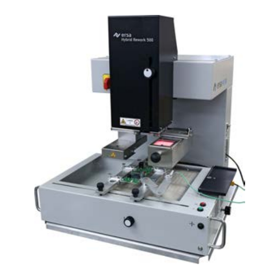
HR 500
Rework-System
Translation of the original operating manual: 3BA00246-01 | Serial
No.: ..........................................
Ersa GmbH
Leonhard-Karl-Str. 24
97877 Wertheim
www.ersa.de
Rev. 1
Printing date: 26/03/2020
Phone +49 9342/800-136
Fax +49 9342/800-132
Mobile +49 171 241 846 8
service-ersa@kurtzersa.de
Advertisement
Table of Contents

Related Manuals for Kurtz Ersa HR 500


Summary of Contents for Kurtz Ersa HR 500
- Page 1 HR 500 Rework-System Translation of the original operating manual: 3BA00246-01 | Serial No.: .......... Ersa GmbH Leonhard-Karl-Str. 24 97877 Wertheim Phone +49 9342/800-136 www.ersa.de Fax +49 9342/800-132 Rev. 1 Mobile +49 171 241 846 8 Printing date: 26/03/2020 service-ersa@kurtzersa.de...
-
Page 3: Table Of Contents
Scope of delivery............................. 27 Available options............................. 27 Unpacking, setting up and connecting the Rework System ................ 29 4.6.1 Unpacking ............................ 29 4.6.2 Set up.............................. 29 4.6.3 Remove the transport lock ....................... 30 4.6.4 Connecting the machine........................ 30 Ersa GmbH Operating_instructions HR 500 DE 3BA00246-01 | Rev. 1 iii / 124... - Page 4 6.14 The display and switch row top right ...................... 94 6.15 Switching off the Rework System........................ 96 Tutorial – Soldering or unsoldering a component.................... 98 Insert the PCB.............................. 98 Adjust the pipette size to the component ...................... 99 Ersa GmbH Operating_instructions HR 500 DE 3BA00246-01 | Rev. 1 iv / 124...
- Page 5 Performing a HRSoft 2 update ........................ 119 Spare and wear parts............................ 121 Read this first! ............................... 122 9.1.1 Target readers, permitted spare parts ................... 122 Nameplate and machine number ......................... 122 Spare parts .............................. 123 Ersa GmbH Operating_instructions HR 500 DE 3BA00246-01 | Rev. 1 v / 124...
-
Page 7: Introduction
Information about this manual ......................... 9 1.2.1 Pictogram and symbol explanations.................... 10 1.2.1.1 Prevailing term definitions in this instruction manual............ 11 1.2.1.2 Warnings......................... 12 1.2.1.3 Rule notices ........................ 13 1.2.1.4 Prohibition notices...................... 14 1.2.2 Target readers group ........................ 15 1.2.3 Copyright, liability.......................... 15 Ersa GmbH Operating_instructions HR 500 DE 3BA00246-01 | Rev. 1 7 / 124... -
Page 8: Product Information
To the extent permitted by law, liability for direct, consequential and indirect dam- age resulting from the purchase of this product is ruled out. Ersa GmbH Operating_instructions HR 500 DE 3BA00246-01 | Rev. 1 8 / 124... -
Page 9: Information About This Manual
In addition, for the machine operation, local safety and accident prevention regu- lations must also be complied with! d) Always keep these instructions near the machine, in a place accessible to all users at any time! Ersa GmbH Operating_instructions HR 500 DE 3BA00246-01 | Rev. 1 9 / 124... -
Page 10: Pictogram And Symbol Explanations
If not avoided, death, serious injury or material damage can result. a) Measures are described in the following text to avert a danger. NOTE The hereinafter highlighted text passages contain explanations, further information or tips. Ersa GmbH Operating_instructions HR 500 DE 3BA00246-01 | Rev. 1 10 / 124... -
Page 11: Prevailing Term Definitions In This Instruction Manual
Adjust the (A) regulator air pressure to 2.5 bar. ð The symbol on the screen turns green. b) Reinstall the cover panel. ð The air pressure has been properly set. Ersa GmbH Operating_instructions HR 500 DE 3BA00246-01 | Rev. 1 11 / 124... -
Page 12: Warnings
We use the following pictograms for warnings: WARNING Dangerous electrical voltage! Danger of electrocution! WARNING Hot surfaces, hot gases! Burn hazard! WARNING Laser beam! Risk of retinal burns! WARNING Risk of injury! Hand injury risk! Ersa GmbH Operating_instructions HR 500 DE 3BA00246-01 | Rev. 1 12 / 124... -
Page 13: Rule Notices
1 | Introduction Information about this manual 1.2.1.3 Rule notices NOTE Read the operating instructions! NOTE Wear protective goggles! NOTE Disconnect power! NOTE ESD-hazardous components! Ersa GmbH Operating_instructions HR 500 DE 3BA00246-01 | Rev. 1 13 / 124... -
Page 14: Prohibition Notices
Information about this manual 1.2.1.4 Prohibition notices We use the following pictograms for prohibition notices: Prohibition, in general! Do not touch! No fire and naked light! Eating and drinking prohibited! No smoking!! Ersa GmbH Operating_instructions HR 500 DE 3BA00246-01 | Rev. 1 14 / 124... -
Page 15: Target Readers Group
\product_data\049\] folder on the drive of your machine PC. All other available lan- guages are translations of the original operating instructions. Should any discrepan- cies occur in the translated text, consult the original operating instructions (German) for clarification or contact the machine manufacturer. Ersa GmbH Operating_instructions HR 500 DE 3BA00246-01 | Rev. 1 15 / 124... - Page 16 1 | Introduction Information about this manual Ersa GmbH Operating_instructions HR 500 DE 3BA00246-01 | Rev. 1 16 / 124...
-
Page 17: Technical Data
2 Technical data Connection data.............................. 18 Printed circuit boards and components...................... 18 General data.............................. 18 Ambient conditions............................ 18 Heating system.............................. 18 Axis system.............................. 19 Cameras ................................ 19 PC system requirements .......................... 19 Ersa GmbH Operating_instructions HR 500 DE 3BA00246-01 | Rev. 1 17 / 124... -
Page 18: Connection Data
(%, non condensing) 40…60 2.5 Heating system Bottom radiator Designation Heating type Keramic heating elements, medium wave, infrared, reactive Radiator cassette dimensions 270 x 270 (width x depth, mm) Number of heating zones Ersa GmbH Operating_instructions HR 500 DE 3BA00246-01 | Rev. 1 18 / 124... -
Page 19: Axis System
2.8 PC system requirements For the PC configuration required for your Rework System, refer to the PDF docu- ment 3BA00212 “PC-Konfigurationsempfehlung_Ersa-IRSOFT-HRSoft-ImageDoc”. This document can found on the Ersa Rework USB stick (3BA000149). Ersa GmbH Operating_instructions HR 500 DE 3BA00246-01 | Rev. 1 19 / 124... - Page 20 2 | Technical data PC system requirements Ersa GmbH Operating_instructions HR 500 DE 3BA00246-01 | Rev. 1 20 / 124...
-
Page 21: For Your Safety
Safety instructions for maintenance, service, specific work, troubleshooting .......... 23 Safety instructions for certain machine and system parts................ 24 3.5.1 Hot device............................ 24 3.5.2 Laser equipment .......................... 24 3.5.3 Using a solder fume extractor, plug available .................. 24 Retrofitting and changes.......................... 24 Ersa GmbH Operating_instructions HR 500 DE 3BA00246-01 | Rev. 1 21 / 124... -
Page 22: General Safety Instructions
Risk of burns when dealing with fuels, additives and liquid metal! a) Be aware of the in-house provision for protective clothing! b) Work on the hot machine must only be carried out by trained and qualified per- sonnel! Ersa GmbH Operating_instructions HR 500 DE 3BA00246-01 | Rev. 1 22 / 124... -
Page 23: Safety Instructions For Certain Operating Phases
During commissioning, ensure switching on and off processes and monitoring dir- ections are in accordance with the operating instruction manual! NOTE Disposal a) Provide safe and environmentally friendly disposal of packaging materials! Ersa GmbH Operating_instructions HR 500 DE 3BA00246-01 | Rev. 1 23 / 124... -
Page 24: Safety Instructions For Certain Machine And System Parts
ü So, please always make sure that retrofitting or modifying the machine does not pose any problem: a) Prior to making any changes to the machine, or altering its parameters, contact the machine manufacturer! Ersa GmbH Operating_instructions HR 500 DE 3BA00246-01 | Rev. 1 24 / 124... -
Page 25: Transport, Installation, Storage, Disposal
Remove the transport lock ....................... 30 4.6.4 Connecting the machine........................ 30 4.6.5 Assembling an RPC camera (Optional) ..................... 33 4.6.6 Assembling the Accu-TC holder and air deflector ................ 35 Transporting the Rework System........................ 36 Disposal ................................ 37 Ersa GmbH Operating_instructions HR 500 DE 3BA00246-01 | Rev. 1 25 / 124... -
Page 26: Information Concerning Machine Transport And Storage
If the indicator has turned blue, this means that: during transport the machine was excessively tilted. d) If the indicator has turned blue, this must be specified in the consignment note! Fig. 1: Indicator not coloured Ersa GmbH Operating_instructions HR 500 DE 3BA00246-01 | Rev. 1 26 / 124... -
Page 27: Scope Of Delivery
Item number Nozzle Ø 1 mm, metallic 0HR5520-05010 Nozzle Ø 2 mm, metallic 0HR5520-10020 Nozzle Ø 3.3 mm with silicone cup Ø 2 0HR5520-20033 RPC camera 0HR510 Dip & Print station 0PR100 Ersa GmbH Operating_instructions HR 500 DE 3BA00246-01 | Rev. 1 27 / 124... - Page 28 0HR504-01 AccuTC 2.0 thermocouple 0HR645 K-type thermocouple wire with plug 0IR4510-02 The following devices can be connected to the HR 500 unit. They can be controlled via the HR 500 unit: Designation Item number Fume extraction Ersa EASY ARM 1...
-
Page 29: Unpacking, Setting Up And Connecting The Rework System
Fig. 2: Do not lift the Rework System at the bottom heating a) The Rework System should be grasped by two people at the authorized lifting points and lifted out of the carton box. The Rework System weighs about 55 kg. Ersa GmbH Operating_instructions HR 500 DE 3BA00246-01 | Rev. 1 29 / 124... -
Page 30: Remove The Transport Lock
Close the opening on the machine upper side with the sealing plug included in the accessory package (4). 4.6.4 Connecting the machine ü Connecting the machine: a) remove all accessories from the packaging, unwrap them and lay them out. Ersa GmbH Operating_instructions HR 500 DE 3BA00246-01 | Rev. 1 30 / 124... - Page 31 Plug the modular cable (RJ-12, 2 m, order no. 317096) into the socket (1) of the soldering station. ð The fume extractor switches on automatically at working temperatures above 120° C. For this purpose, please also read Chapter Assembling an RPC camera (Optional) [} 33]. Ersa GmbH Operating_instructions HR 500 DE 3BA00246-01 | Rev. 1 31 / 124...
- Page 32 Ersa “Easy Arm” with prefilter, HEPA, particle filter and ac- tivated carbon filter. The device is equipped with a suitable connection for the solder- ing fume extraction system. The soldering fume extraction system prevents the device from accumulating dirt quickly. Ersa GmbH Operating_instructions HR 500 DE 3BA00246-01 | Rev. 1 32 / 124...
-
Page 33: Assembling An Rpc Camera (Optional)
2 RPC camera with adjustment 4 Telescopic rail with spacer plate b) Assemble the camera. Fix the screw of the camera mount (6) to the telescopic rail, as shown in the following picture: Ersa GmbH Operating_instructions HR 500 DE 3BA00246-01 | Rev. 1 33 / 124... - Page 34 Rework System, see the following example picture. Fig. 6: Mounted RPC camera d) Connect the Ethernet cable and the LED lighting cable to the Rework System. For this purpose, please read Chapter Connecting Ersa GmbH Operating_instructions HR 500 DE 3BA00246-01 | Rev. 1 34 / 124...
-
Page 35: Assembling The Accu-Tc Holder And Air Deflector
Select an air deflector and let the lower end of the heating head snap in from below. Ersa GmbH Operating_instructions HR 500 DE 3BA00246-01 | Rev. 1 35 / 124... -
Page 36: Transporting The Rework System
Screw in the shipping/restraining bolt on the Rework System upper part (3). b) Screw in the shipping/restraining bolt between the heating head and the Vis- ion-Box (4). c) Use the original packing for shipping the Rework System. Ersa GmbH Operating_instructions HR 500 DE 3BA00246-01 | Rev. 1 36 / 124... -
Page 37: Disposal
ð Only after these operations are concluded is it possible to start the disposal procedure. ü If it is not possible to properly scrap the machine at the user’s premises: a) Appoint a certified disposal company. Ersa GmbH Operating_instructions HR 500 DE 3BA00246-01 | Rev. 1 37 / 124... - Page 38 This way, you can make your contribution to the reuse or other forms of use of waste to protect the en- vironment and human health. Ersa GmbH Operating_instructions HR 500 DE 3BA00246-01 | Rev. 1 38 / 124...
-
Page 39: Commissioning
5 | Commissioning 5 Commissioning Setting up the PC............................. 40 Calibrate the pipette distances and the optical axle.................. 42 Mount the pipette............................ 49 Ersa GmbH Operating_instructions HR 500 DE 3BA00246-01 | Rev. 1 39 / 124... -
Page 40: Setting Up The Pc
Click on the Windows start button once and enter “Network.” b) Click on the “Network status” line in the Windows start menu. c) Click on “Change adapter options” in the “Status” dialog. ð The network adapters will be displayed. Ersa GmbH Operating_instructions HR 500 DE 3BA00246-01 | Rev. 1 40 / 124... - Page 41 Install the HRSoft 2 program. a) In the HRSoft2_xxx folder search for the installation program “setup.exe” for HRSoft 2. Double click on this file. To do so, follow the instructions and confirm dialogues with OK/Continue. Ersa GmbH Operating_instructions HR 500 DE 3BA00246-01 | Rev. 1 41 / 124...
-
Page 42: Calibrate The Pipette Distances And The Optical Axle
ð The HRSoft 2 program starts. The Rework System and Rework processes can be controlled via the HRSoft 2 program. HRSoft 2 starts in the administrator mode and shows the tab [Rework]. Ersa GmbH Operating_instructions HR 500 DE 3BA00246-01 | Rev. 1 42 / 124... - Page 43 Calibration Step 1: Calibrating the pipette distances through function [Start device setup] a) In the header, select tab [Administration]. b) In the left menu bar, select menu item [Device options]. Ersa GmbH Operating_instructions HR 500 DE 3BA00246-01 | Rev. 1 43 / 124...
- Page 44 Style Rework Archive User administration Profile management Administration Back Next HRSoft 2 options Zero Point Teach In Tray Table Teach In Vision Box Teach In Graph options Device options Ersa GmbH Operating_instructions HR 500 DE 3BA00246-01 | Rev. 1 44 / 124...
- Page 45 In field [Process automation] deactivate the first work step [Desoldering], the second work step [Placement] must be activated. d) Click button [Start/Reference]. ð The wizard starts at work step 4 [Provide]. Ersa GmbH Operating_instructions HR 500 DE 3BA00246-01 | Rev. 1 45 / 124...
- Page 46 Use the mouse wheel or the zoom control on the screen to enlarge the calibra- tion target to full screen. Move the camera image with the mouse until the cal- ibration target reaches the screen centre, see the picture below. Ersa GmbH Operating_instructions HR 500 DE 3BA00246-01 | Rev. 1 46 / 124...
- Page 47 With a 2.5 mm Allen wrench slightly loosen the screw in the centre behind the Visionbox (approx. ¼ rotation), see the picture below. ð Now the optical axles can be modified. Ersa GmbH Operating_instructions HR 500 DE 3BA00246-01 | Rev. 1 47 / 124...
- Page 48 After rotation, slide the Visionbox to the left below the camera and verify the outcome on the screen. Repeat this process until the calibration target is displayed congruently on the background and with a uniform border. Ersa GmbH Operating_instructions HR 500 DE 3BA00246-01 | Rev. 1 48 / 124...
-
Page 49: Mount The Pipette
Click tab [Manual Mode] to view the button row for manual operation. c) Click the “Pipette” pushbutton ð A submenu with further pushbuttons is displayed: d) Press the pushbutton (10) until the pipette and its holder have moved far enough downwards. Ersa GmbH Operating_instructions HR 500 DE 3BA00246-01 | Rev. 1 49 / 124... - Page 50 Screw on the pipette and tighten it only slightly. The pipette is then driven upwards by the Rework System. For this purpose, please also read Chapter Spare parts where you can find a list of available pipettes. Ersa GmbH Operating_instructions HR 500 DE 3BA00246-01 | Rev. 1 50 / 124...
-
Page 51: Function Description
The [device settings] dialog ...................... 88 6.12.3.1 The button [Start Adjustment] .................. 90 6.13 The button [Manual Mode] .......................... 92 6.14 The display and switch row top right ...................... 94 6.15 Switching off the Rework System........................ 96 Ersa GmbH Operating_instructions HR 500 DE 3BA00246-01 | Rev. 1 51 / 124... -
Page 52: Read This First
ESD (ESD = electrostatic discharge) safe workplace will be suitable. The HR 500 can be easily integrated into such an environment. Through one of the pushbuttons on the front, the user can connect an ESD wrist band. The housing of the HR 500 is connected to the protective conductor of the voltage supply network via the interconnection cable. -
Page 53: Overview Of The Machine Parts
15 Setscrew for fine adjustment of the board in Y direction. 5 Visionbox with camera. Red lighting above, white 16 Thermocouple holder lighting below 6 Handle for Visionbox and heating head displace- 17 Bottom heating, 2 zones ment Ersa GmbH Operating_instructions HR 500 DE 3BA00246-01 | Rev. 1 53 / 124... -
Page 54: Switching On The Rework System And Starting Hrsoft 2
[Administrator] or [Standard user]. ð If the network connection icon top right or next to the temperature display turns green, the connection between the Rework System and the PC is es- tablished. Ersa GmbH Operating_instructions HR 500 DE 3BA00246-01 | Rev. 1 54 / 124... -
Page 55: The Top Bar In The Hrsoft 2 Program
– Display and button row on the right: Temperature display, network display, user name and system status. With regard to this, please read Chapter The dis- play and button sequence in the right upper corner. Ersa GmbH Operating_instructions HR 500 DE 3BA00246-01 | Rev. 1 55 / 124... -
Page 56: Temporarily Editing The Soldering Profile In The [Rework] Tab
[Profile management] tabu- made to the soldering profile will lator. be lost. With regard to this, please read Chapter The chart in the [Rework] tabulator. Ersa GmbH Operating_instructions HR 500 DE 3BA00246-01 | Rev. 1 56 / 124... - Page 57 “standard user,” you may not save changes, and the [0502] tab is not vis- ible.Profile management The functions of tab [Rework] are described in detail in the following chapter. Ersa GmbH Operating_instructions HR 500 DE 3BA00246-01 | Rev. 1 57 / 124...
-
Page 58: Use Of The Soldering Profile In The [Rework] Tabulator
(5). With regard to this, please read the Chapters on The chart in the [Profile manage- ment] tabulator [} 82]. Ersa GmbH Operating_instructions HR 500 DE 3BA00246-01 | Rev. 1 58 / 124... -
Page 59: The Tabulators [Information], [Heating Setting] And The Arrow Key [Image Processing]
For all changes made in tab [Rework], the following applies: changes are accepted but cannot be saved. If you switch from tab [Rework] to another tab, all changes will be lost. Ersa GmbH Operating_instructions HR 500 DE 3BA00246-01 | Rev. 1 59 / 124... - Page 60 [Drop]: Dropping the component via the PCB. – [Drop height]: During soldering. Height above the PCB at which the component is dropped onto the PCB. Can only be changed when parameter [Drop] is selec- ted. Ersa GmbH Operating_instructions HR 500 DE 3BA00246-01 | Rev. 1 60 / 124...
- Page 61 The correct soldering profile settings should be specified in tabProfile manage- ment] beforehand. Only possible as an “Administrator” user. For this purpose, please read Chapter The [Information] tabulator under the [User management] tabulator. Ersa GmbH Operating_instructions HR 500 DE 3BA00246-01 | Rev. 1 61 / 124...
-
Page 62: The [Heating Setting] Tabulator Under The [Rework] Tabulator
[Heater config] will now apply to all heating phases. If button [Change all zones] is disabled, different heating parameters can be assigned to each of the four heat- ing phases. The following parameters can be changed in tab [Heater config]: Ersa GmbH Operating_instructions HR 500 DE 3BA00246-01 | Rev. 1 62 / 124... - Page 63 The correct soldering profile settings should be specified in tabProfile manage- ment] beforehand. Only possible as an “Administrator” user. For this purpose, please read Chapter The [Heating setting] tabulator under the [Rework] tabulator [} 62]. Ersa GmbH Operating_instructions HR 500 DE 3BA00246-01 | Rev. 1 63 / 124...
- Page 64 6.5.3.4 The tab with the arrow buttons [Image processing] under the tab [Rework] Do not use the functions under tab [Image processing]. In the field [Comment:] the user can read the information saved by the Adminis- trator in the soldering profile. Ersa GmbH Operating_instructions HR 500 DE 3BA00246-01 | Rev. 1 64 / 124...
-
Page 65: The Chart In The [Rework] Tabulator
For the temperature values of the thermocouples, the left Y-scale of the chart with the temperature values applies. For correcting variables (e.g. TC infrared coil, Outer IR emitter) the right Y scale in the chart indicating maximum values of 100% ap- plies. Ersa GmbH Operating_instructions HR 500 DE 3BA00246-01 | Rev. 1 65 / 124... -
Page 66: The [Process Automation] Button Row
The correct soldering profile settings should be specified in the [Profile manage- ment] tab beforehand. Only possible as “Administrator” user. With regard to this, please read Chapter The [Process automation] buttons under the [Profile manage- ment] tabulator [} 84]. Ersa GmbH Operating_instructions HR 500 DE 3BA00246-01 | Rev. 1 66 / 124... -
Page 67: The [Archive] Tabulator
– [Lens]: Lens used in the process. Without function, can be freely adjusted in the chart. – [pipette]: Pipette specified in the process. Without function, can be freely ad- justed in the chart. Range [Process automation] under the table shows the process steps adopted. Ersa GmbH Operating_instructions HR 500 DE 3BA00246-01 | Rev. 1 67 / 124... -
Page 68: The [Show Chart] Button
The right Y scale of the chart with up to 100% percentages applies to them. – Trash button on chart key: Delete the selected measuring line. Tab [Information]: Display of the soldering process parameters. Ersa GmbH Operating_instructions HR 500 DE 3BA00246-01 | Rev. 1 68 / 124... - Page 69 – [Device info] tab: Display of basic information about the device and software versions. – Tab [Image processing]: Display of image processing settings. The X button to close the chart is located on the top right of the chart. Ersa GmbH Operating_instructions HR 500 DE 3BA00246-01 | Rev. 1 69 / 124...
-
Page 70: The [User Management] Tabulator
– Button [Duplicate]: Creates a copy of a user. Select a user and click on button [Duplicate] to create a copy of this user. Then enter all parameter fields for the new user into the greyed-out column on the right. Ersa GmbH Operating_instructions HR 500 DE 3BA00246-01 | Rev. 1 70 / 124... - Page 71 Highlight the user to be deleted. ð A button will appear in the user line as a red trash icon. b) Click on the trash button. ð The user has been deleted. Ersa GmbH Operating_instructions HR 500 DE 3BA00246-01 | Rev. 1 71 / 124...
-
Page 72: Editing The Soldering Profile In The [Profile Management] Tab And Changing It Permanently
– Button “User name” to change user – Button to open dialog [System state] Button to close the HRSoft 2 program For this purpose, please read Chapter The top bar in the HRSoft 2 program [} 55]. Ersa GmbH Operating_instructions HR 500 DE 3BA00246-01 | Rev. 1 72 / 124... -
Page 73: Create, Copy, Delete And Save Soldering Profiles In The [Profile Management] Tabulator
Create a new soldering profile a) Click on the “plus symbol” on the soldering profile list. ð The [Select a profile name] window opens. Ersa GmbH Operating_instructions HR 500 DE 3BA00246-01 | Rev. 1 73 / 124... - Page 74 Click on the [Confirm] button. ð The new profile is added at the end of the profile list. d) Save the profile with the “floppy disk” button on the soldering profile list. Ersa GmbH Operating_instructions HR 500 DE 3BA00246-01 | Rev. 1 74 / 124...
- Page 75 In the soldering profile list, click on the soldering profile you wish to save. b) Click on the “floppy disk” button on the soldering profile list. ð The copied profile was saved. Ersa GmbH Operating_instructions HR 500 DE 3BA00246-01 | Rev. 1 75 / 124...
-
Page 76: The Tabulators [Information], [Heating Setting] And The Arrow Key [Image Processing]
Adaptor (head) Heating head position Distance 50 mm Heating head L-head Lens pipette Pipette 1 Placement Dip mode No automation Placement mode Placement Drop height Process automation Desoldering Placement Inspection Soldering Inspection Ersa GmbH Operating_instructions HR 500 DE 3BA00246-01 | Rev. 1 76 / 124... - Page 77 PCB. Can only be changed when parameter [Drop] is selec- ted. For the temporary modification of the soldering profile parameters, please read Chapter The [Information] tabulator under the [Rework] tabulator. Ersa GmbH Operating_instructions HR 500 DE 3BA00246-01 | Rev. 1 77 / 124...
-
Page 78: The [Heating Setting] Tabulator Under The [Profile Management] Tabulator
– Horizontal controller: Distribution of the upper heating in % between hot-air heating (fan symbol) and infrared heating (heating element symbol). Infrared heating is not suitable for heating shiny surfaces. Ersa GmbH Operating_instructions HR 500 DE 3BA00246-01 | Rev. 1 78 / 124... - Page 79 This will ensure a safe process. To learn more on how to change the heating parameters, read the The [Heating setting] tabulator under the [Rework] tabulatorchapter. Ersa GmbH Operating_instructions HR 500 DE 3BA00246-01 | Rev. 1 79 / 124...
-
Page 80: The [More] Tab Under The [Profile Management] Tab / Create User
List of users, who can view and use this soldering profile in tab [Rework]. This may only be assigned here. Assigning a user to the soldering profile a) Click the “plus“ sign. Ersa GmbH Operating_instructions HR 500 DE 3BA00246-01 | Rev. 1 80 / 124... - Page 81 Move the mouse over the user name to be deleted. ð A red trash icon will appear behind the username. c) Click the trash icon. ð A user was removed from the soldering profile. Ersa GmbH Operating_instructions HR 500 DE 3BA00246-01 | Rev. 1 81 / 124...
-
Page 82: The Chart In The [Profile Management] Tabulator
– Heating phase [Tinit] – T1, T1 – T2 and T2 – T3: Heating-up phases that allow for different configurations. The heating phases of the soldering and unsolder- ing process may differ starting from T2 . Ersa GmbH Operating_instructions HR 500 DE 3BA00246-01 | Rev. 1 82 / 124... - Page 83 Please remember that the components should not be heated as quickly as possible: in fact, only a slower heating process can ensure an even temperature distribution. This will ensure a safe process Ersa GmbH Operating_instructions HR 500 DE 3BA00246-01 | Rev. 1 83 / 124...
-
Page 84: The [Process Automation] Buttons Under The [Profile Management] Tabulator
– [Inspection]: Final check of the soldering results with the vision box. For an example of soldering process, please refer to the Tutorial – Soldering or un- soldering a component chapter. Ersa GmbH Operating_instructions HR 500 DE 3BA00246-01 | Rev. 1 84 / 124... -
Page 85: The [Management] Tabulator With Three Dialog Windows
The database stores user profiles and soldering processes among other things. In field [Database information] (see the description of the following functions), cor- rect parameters must be entered to access the database. Ersa GmbH Operating_instructions HR 500 DE 3BA00246-01 | Rev. 1 85 / 124... - Page 86 A file with *.bak extension is created. Use this function to send the data- base data to another computer. – Button [Database restore]: A secured database (file extension *.bak) can be read. Ersa GmbH Operating_instructions HR 500 DE 3BA00246-01 | Rev. 1 86 / 124...
-
Page 87: The [Chart Settings] Dialog
The measured curves in the chart can be displayed/hidden also during the current soldering process. – Column [Show]: to display/hide the measured curve. – Column [Colour]: colour of the measured curve. Click on the coloured square to display all available colours. Ersa GmbH Operating_instructions HR 500 DE 3BA00246-01 | Rev. 1 87 / 124... -
Page 88: The [Device Settings] Dialog
[Channel TC 1] to [Channel TC 2] to offset them. Button [Send] The temperature correction values were adopted and the Rework System will dis- play the calibrated values of the temperature sensors. Ersa GmbH Operating_instructions HR 500 DE 3BA00246-01 | Rev. 1 88 / 124... - Page 89 – Before transporting the Rework System to another location, use button [Travel in transport position] to move the axis system to the safe transport position, thus avoiding any damage in transit! For this purpose, please also read Chapter [Deactivate the HR 550]. Ersa GmbH Operating_instructions HR 500 DE 3BA00246-01 | Rev. 1 89 / 124...
-
Page 90: The Button [Start Adjustment]
Click button [Next] or press the “Next” button. Ersa GmbH Operating_instructions HR 500 DE 3BA00246-01 | Rev. 1 90 / 124... - Page 91 Move the Visionbox to the left position, until the Vision Box is below the pipette. b) Click button [Next] or press the “Next” button. ð The pipette touches the Visionbox. ð The calibration ends and the result is saved. Ersa GmbH Operating_instructions HR 500 DE 3BA00246-01 | Rev. 1 91 / 124...
-
Page 92: The Button [Manual Mode]
– 7: Switch on/off the Vision Box lighting. This opens a submenu for selection: red component camera at the top, white PCB camera at the bottom. – 8: Manually trigger motor movements. A submenu with further pushbuttons is displayed: Ersa GmbH Operating_instructions HR 500 DE 3BA00246-01 | Rev. 1 92 / 124... - Page 93 – 11. The pipette moves down up to the contact. – 12. Stop the pipette movement. – 13. No function. For details about the machine parts, please also read Chapter Overview of the ma- chine parts. Ersa GmbH Operating_instructions HR 500 DE 3BA00246-01 | Rev. 1 93 / 124...
-
Page 94: The Display And Switch Row Top Right
Range [System information] – At the top: Display of the statuses of the basic Rework System components. – Below [System Parameters]: Current levels of the installed HRSoft 2 version and firmware Ersa GmbH Operating_instructions HR 500 DE 3BA00246-01 | Rev. 1 94 / 124... - Page 95 – Feedback menu item: Dialog box to give the manufacturer (Ersa) a positive or negative feedback on the Rework System. Red button to the far right – Closes the HRSoft 2 program. Ersa GmbH Operating_instructions HR 500 DE 3BA00246-01 | Rev. 1 95 / 124...
-
Page 96: Switching Off The Rework System
ð After editing the HRS file, you will be asked if you want to save the changes. b) Use the main switch to turn off the Rework System. c) Shut down the PC. Ersa GmbH Operating_instructions HR 500 DE 3BA00246-01 | Rev. 1 96 / 124... - Page 97 6 | Function description Switching off the Rework System Ersa GmbH Operating_instructions HR 500 DE 3BA00246-01 | Rev. 1 97 / 124...
-
Page 98: Tutorial - Soldering Or Unsoldering A Component
Tighten the four knurled screws (3). e) After loosening the knurled screws (4), the clamping can be adjusted to the po- sition and the angle of unsymmetrical PCBs as well. Ersa GmbH Operating_instructions HR 500 DE 3BA00246-01 | Rev. 1 98 / 124... -
Page 99: Adjust The Pipette Size To The Component
Press the pushbutton (10) until the pipette and its holder have moved far enough downwards. e) Screw on the pipette and tighten it only slightly For this purpose, please also read Chapter Spare parts where you can find a list of available pipettes. Ersa GmbH Operating_instructions HR 500 DE 3BA00246-01 | Rev. 1 99 / 124... -
Page 100: Position A Thermocouple
PCB. For exact values, the thermocouple should be in contact with conductive trace areas, e.g. trace or mass. Note: The infrared sensor is not suitable for glossy and reflective surfaces. Ersa GmbH Operating_instructions HR 500 DE 3BA00246-01 | Rev. 1 100 / 124... -
Page 101: Shielding Heat Sensitive Components
7.4 Shielding heat sensitive components Use reflective strip and/or an adequate air deflector for shielding purposes. Select an air deflector (1) and let the lower end of the heating head (2) snap in from below. Ersa GmbH Operating_instructions HR 500 DE 3BA00246-01 | Rev. 1 101 / 124... -
Page 102: Activate A Soldering Profile And Prepare The Soldering Process
Check all the soldering profile settings, consisting of the chart, the buttons [Process automation] and the three tabs [Information], [Heater config] and the tab with the small arrow button (Image processing). If necessary, make corrections. Ersa GmbH Operating_instructions HR 500 DE 3BA00246-01 | Rev. 1 102 / 124... -
Page 103: Start The Process And Work With The Assistant
Fig. 22: All five steps are activated a) Click on the [Start] button. ð The Wizard starts and executes the various steps divided into several tasks. Perform all activities as required by the assistant. Ersa GmbH Operating_instructions HR 500 DE 3BA00246-01 | Rev. 1 103 / 124... - Page 104 In the information row over the graph you will find a description of the required tasks. In the dark area on the right you may view the most important process para- meters. Ersa GmbH Operating_instructions HR 500 DE 3BA00246-01 | Rev. 1 104 / 124...
-
Page 105: Task 1 "Alignment
ð The selected desoldering process starts and the progress can be followed in the chart. At the end the pipette picks up the desoldered component from the PCB. d) Go to the next step. Also see 2 Position a thermocouple [} 100] Ersa GmbH Operating_instructions HR 500 DE 3BA00246-01 | Rev. 1 105 / 124... -
Page 106: Task 2 "Desoldering
RPC camera light intensity Auto exposure Chart information – Column [Show]: display/hide the measuring curves. – Column [Colour]: colour of the measuring curve. Click the coloured square to see all available colours. Ersa GmbH Operating_instructions HR 500 DE 3BA00246-01 | Rev. 1 106 / 124... - Page 107 Heating information The lower field shows the updated status of the heating elements and hot air blower. a) When the soldering process ends, go to the next step. Ersa GmbH Operating_instructions HR 500 DE 3BA00246-01 | Rev. 1 107 / 124...
-
Page 108: Work Step 3 "Position" And Clean The Desoldering Point
ð using, for instance, the Ersa soldering i-Tool bit, e.g. with the following sol- dering tips: PowerWell 0102WDLF23/SB (small), 0102ADLF40/SB (medium) or 0102ZDLF150/SB (large) c) Remove flux residue with Ersa Flux Remover (0FR200). d) Dry the solder joints with a clean, lint-free cloth. Ersa GmbH Operating_instructions HR 500 DE 3BA00246-01 | Rev. 1 108 / 124... -
Page 109: Task 4 "Preparation
Dip-template. Then the com- ponent is picked up from the DIP-template, aligned and placed in soldering position. Fig. 24: Dip template on the component tray Ersa GmbH Operating_instructions HR 500 DE 3BA00246-01 | Rev. 1 109 / 124... -
Page 110: Task 5 "Alignment
For example, in case of large components, click the [Split optics] button to see an enlarged display for the comparison of widely spaced image areas. Now click four times with the small blue rectangle on the four points that you want to see enlarged. Ersa GmbH Operating_instructions HR 500 DE 3BA00246-01 | Rev. 1 110 / 124... - Page 111 Fig. 26: Split screen view with simultaneous display of the four corners of a large component f) If the component is congruent with the solder joint, follow the next work step. ð The component is placed on the board. Ersa GmbH Operating_instructions HR 500 DE 3BA00246-01 | Rev. 1 111 / 124...
-
Page 112: Task 6 "Inspection
Close the full-screen display by clicking the small red circle button in the upper right corner. b) If the component is correctly positioned, follow the next work step. Ersa GmbH Operating_instructions HR 500 DE 3BA00246-01 | Rev. 1 112 / 124... -
Page 113: Task 7 "Soldering
RPC camera light intensity Auto exposure Information chart – Column [Show]: Show/hide the measurement curves. – Column [Colour]: Colour of the measurement curve. Click on the coloured square to view all available colours. Ersa GmbH Operating_instructions HR 500 DE 3BA00246-01 | Rev. 1 113 / 124... - Page 114 Heating information In the lower area, the current status of the thermocouples and blower elements is displayed. a) When the soldering process is over, move on to the next task. Ersa GmbH Operating_instructions HR 500 DE 3BA00246-01 | Rev. 1 114 / 124...
-
Page 115: Task 8 "Inspection
Release Provide Inspection Soldering Inspection Alignment Complete Parameters Split optics White light intensity RPC camera light intensity Automatic brightness a) If the component is correctly positioned, follow the next work step. Ersa GmbH Operating_instructions HR 500 DE 3BA00246-01 | Rev. 1 115 / 124... -
Page 116: Task 9 "Complete
PowerWell 0102WDLF23/SB (small), 0102ADLF40/SB (medium) or 0102ZDLF150/SB (large) c) Remove any flux material residues (for instance) with the Ersa Flux Remover (0FR200). d) Dry the soldering points with a clean, lint-free cloth. Ersa GmbH Operating_instructions HR 500 DE 3BA00246-01 | Rev. 1 116 / 124... -
Page 117: Service And Maintenance
8 | Service and maintenance 8 Service and maintenance Check the rework system on a weekly basis for any dirt or damages............ 118 Performing a HRSoft 2 update ........................ 119 Ersa GmbH Operating_instructions HR 500 DE 3BA00246-01 | Rev. 1 117 / 124... -
Page 118: Check The Rework System On A Weekly Basis For Any Dirt Or Damages
ü Check ceramic parts in the heating head: a) Check the ceramic parts on the bottom side of the heating head for defects and deformation, and the heating coils in the ceramic parts for defects. Replace when damaged. Ersa GmbH Operating_instructions HR 500 DE 3BA00246-01 | Rev. 1 118 / 124... -
Page 119: Performing A Hrsoft 2 Update
Checking the Netgear switches configuration Switch on the Rework System and the PC. a) Open a web browser and enter the following IP address: 169.254.10.4. Press Enter. ð The Netgear user interface will be displayed. Ersa GmbH Operating_instructions HR 500 DE 3BA00246-01 | Rev. 1 119 / 124... - Page 120 Select menu item “High priority” for both ports in the drop-down menu. h) Click on the “Apply” button to confirm all entries. i) Power cycle the Rework System. ð The process has now been completed. Ersa GmbH Operating_instructions HR 500 DE 3BA00246-01 | Rev. 1 120 / 124...
-
Page 121: Spare And Wear Parts
9 | Spare and wear parts 9 Spare and wear parts Read this first! ............................... 122 9.1.1 Target readers, permitted spare parts ................... 122 Nameplate and machine number ......................... 122 Spare parts .............................. 123 Ersa GmbH Operating_instructions HR 500 DE 3BA00246-01 | Rev. 1 121 / 124... -
Page 122: Read This First
When ordering spare parts always specify the machine number. This number is prin- ted on the nameplate (see illustration above). The nameplate contains other import- ant information about the machine such as machine type, electric power rating, con- formity marking and disposal data. Ersa GmbH Operating_instructions HR 500 DE 3BA00246-01 | Rev. 1 122 / 124... -
Page 123: Spare Parts
Silicone nipple 8.5 for 10 mm nozzle 0HR5520-80 Silicone nipple 2.0 for 3.3 mm nozzle 0HR5520-20 Switch PoE 295847 Power supply 3ET00370 Membrane pump 3VAPU011 3/2 directional valve 119765 Fan bottom heating 313959 Ersa GmbH Operating_instructions HR 500 DE 3BA00246-01 | Rev. 1 123 / 124... - Page 124 9 | Spare and wear parts Spare parts Name Item number Rework powerboard 297445 Rework controllerboard 285856 Stepper motor controller 297444 Ersa GmbH Operating_instructions HR 500 DE 3BA00246-01 | Rev. 1 124 / 124...
Need help?
Do you have a question about the HR 500 and is the answer not in the manual?
Questions and answers