Table of Contents
Advertisement
Quick Links
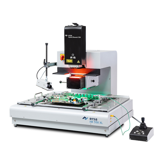
HR 550 XL
Rework-System
Translation of the original operating manual: 3BA00247-01 | Serial
No.: ..........................................
Ersa GmbH
Leonhard-Karl-Str. 24
97877 Wertheim
www.ersa.de
Rev. 1
Printing date: 30/03/2020
Phone +49 9342/800-136
Fax +49 9342/800-132
Mobile +49 171 241 846 8
service-ersa@kurtzersa.de
Advertisement
Table of Contents

Related Manuals for Kurtz Ersa HR 550 XL


Summary of Contents for Kurtz Ersa HR 550 XL
- Page 1 HR 550 XL Rework-System Translation of the original operating manual: 3BA00247-01 | Serial No.: .......... Ersa GmbH Leonhard-Karl-Str. 24 97877 Wertheim Phone +49 9342/800-136 www.ersa.de Fax +49 9342/800-132 Rev. 1 Mobile +49 171 241 846 8 Printing date: 30/03/2020 service-ersa@kurtzersa.de...
-
Page 3: Table Of Contents
ESD-hazardous components ........................... 31 Scope of delivery............................. 32 Available options............................. 32 Unpacking and installing the Rework system .................... 35 Connecting the machine .......................... 39 Insert the heating head........................... 41 Ersa GmbH Operating instructions HR 550 XL EN 3BA00247-01 | Rev. 1 iii / 157... - Page 4 6.13 The [Manual Mode] ............................ 109 6.14 The display and switch row top right ...................... 111 6.15 Switching off the Rework System........................ 113 Tutorial – Soldering or desoldering a component.................... 115 Insert the PCB.............................. 116 Ersa GmbH Operating instructions HR 550 XL EN 3BA00247-01 | Rev. 1 iv / 157...
- Page 5 Target readers, permitted spare parts ................... 150 Nameplate and machine number ......................... 150 Spare parts .............................. 151 9.3.1 Nameplate and machine number.................... 152 10 Annex ................................ 154 10.1 EC Declaration of Conformity........................ 155 Ersa GmbH Operating instructions HR 550 XL EN 3BA00247-01 | Rev. 1 v / 157...
-
Page 7: Introduction
Pictogram and symbol explanations.................... 10 1.2.1.1 Prevailing term definitions in this instruction manual............ 11 1.2.1.2 Warnings......................... 12 1.2.1.3 Binding info about safety shoes .................. 13 1.2.1.4 Prohibition notices...................... 14 1.2.2 Target readers group ........................ 15 1.2.3 Copyright, liability.......................... 15 Ersa GmbH Operating instructions HR 550 XL EN 3BA00247-01 | Rev. 1 7 / 157... -
Page 8: Product Information
To the extent permitted by law, liability for direct, consequential and indirect dam- age resulting from the purchase of this product is ruled out. Ersa GmbH Operating instructions HR 550 XL EN 3BA00247-01 | Rev. 1 8 / 157... -
Page 9: Information About This Manual
In addition, for the machine operation, local safety and accident prevention regu- lations must also be complied with! d) Always keep these instructions near the machine, in a place accessible to all users at any time! Ersa GmbH Operating instructions HR 550 XL EN 3BA00247-01 | Rev. 1 9 / 157... -
Page 10: Pictogram And Symbol Explanations
If not avoided, death, serious injury or material damage can result. a) Measures are described in the following text to avert a danger. NOTE The hereinafter highlighted text passages contain explanations, further information or tips. Ersa GmbH Operating instructions HR 550 XL EN 3BA00247-01 | Rev. 1 10 / 157... -
Page 11: Prevailing Term Definitions In This Instruction Manual
Adjust the (A) regulator air pressure to 2.5 bar. ð The symbol on the screen turns green. b) Reinstall the cover panel. ð The air pressure has been properly set. Ersa GmbH Operating instructions HR 550 XL EN 3BA00247-01 | Rev. 1 11 / 157... -
Page 12: Warnings
We use the following pictograms for warnings: WARNING Dangerous electrical voltage! Danger of electrocution! WARNING Hot surfaces, hot gases! Burn hazard! WARNING Laser beam! Risk of retinal burns! WARNING Risk of injury! Hand injury risk! Ersa GmbH Operating instructions HR 550 XL EN 3BA00247-01 | Rev. 1 12 / 157... -
Page 13: Binding Info About Safety Shoes
When working in areas which are marked with the symbol shown, suitable safety shoes must be worn! NOTE Wear protective goggles! NOTE Disconnect power! NOTE Read the operating instructions! NOTE ESD-hazardous components! Ersa GmbH Operating instructions HR 550 XL EN 3BA00247-01 | Rev. 1 13 / 157... -
Page 14: Prohibition Notices
Information about this manual 1.2.1.4 Prohibition notices We use the following pictograms for prohibition notices: Prohibition, in general! Do not touch! No fire and naked light! Eating and drinking prohibited! No smoking!! Ersa GmbH Operating instructions HR 550 XL EN 3BA00247-01 | Rev. 1 14 / 157... -
Page 15: Target Readers Group
Should any discrepan- cies occur in the translated text, consult the original operating instructions (German) for clarification or contact the machine manufacturer. Ersa GmbH Operating instructions HR 550 XL EN 3BA00247-01 | Rev. 1 15 / 157... - Page 16 1 | Introduction Information about this manual Ersa GmbH Operating instructions HR 550 XL EN 3BA00247-01 | Rev. 1 16 / 157...
-
Page 17: Technical Data
General data.............................. 18 Ambient conditions............................ 19 Connection data.............................. 19 Printed circuit boards and components...................... 19 Heating system.............................. 20 Axis system.............................. 20 Pneumatics.............................. 20 Cameras ................................ 21 PC system requirements .......................... 21 Ersa GmbH Operating instructions HR 550 XL EN 3BA00247-01 | Rev. 1 17 / 157... -
Page 18: General Data
2 | Technical data General data 2.1 General data Designation Width (mm) Depth (mm) Height (mm) ab. 759 Weight (kg) ab. 102, incl. control unit Ersa GmbH Operating instructions HR 550 XL EN 3BA00247-01 | Rev. 1 18 / 157... -
Page 19: Ambient Conditions
Max. PCB size (width x depth, mm) 530 x 610 (20.8“ x 24“) Min. PCB size (width x depth, mm) 20 x 20 Max. PCB thickness (mm) Min. component dimensions (mm) 0.2 x 0.4 Ersa GmbH Operating instructions HR 550 XL EN 3BA00247-01 | Rev. 1 19 / 157... -
Page 20: Heating System
Precision rail guide with step motors Axes Z heating head, Z pipette Repeat accuracy (µm) ± 25 Control unit Bottom heating X/Y-axis and pipette ro- tation 2.7 Pneumatics Designation Maximum inlet pressure (bar, oil-free) Ersa GmbH Operating instructions HR 550 XL EN 3BA00247-01 | Rev. 1 20 / 157... -
Page 21: Cameras
2.9 PC system requirements For the PC configuration required for your Rework System, refer to the PDF docu- ment 3BA00212 “PC-Konfigurationsempfehlung_Ersa-IRSOFT-HRSoft-ImageDoc”. This document can found on the Ersa Rework USB stick (3BA000149). Ersa GmbH Operating instructions HR 550 XL EN 3BA00247-01 | Rev. 1 21 / 157... - Page 22 2 | Technical data PC system requirements Ersa GmbH Operating instructions HR 550 XL EN 3BA00247-01 | Rev. 1 22 / 157...
-
Page 23: For Your Safety
Safety instructions for certain machine and system parts................ 27 3.5.1 Hot device............................ 27 3.5.2 Laser equipment .......................... 27 3.5.3 Using a solder fume extractor, plug available .................. 27 Retrofitting and changes.......................... 27 Ersa GmbH Operating instructions HR 550 XL EN 3BA00247-01 | Rev. 1 23 / 157... -
Page 24: General Safety Instructions
Risk of burns when dealing with fuels, additives and liquid metal! a) Be aware of the in-house provision for protective clothing! b) Work on the hot machine must only be carried out by trained and qualified per- sonnel! Ersa GmbH Operating instructions HR 550 XL EN 3BA00247-01 | Rev. 1 24 / 157... -
Page 25: Safety Instructions For Certain Operating Phases
Severe or fatal injuries from flammable substances! Fire and explosion hazard due to overheating! a) Do not leave the machine running unattended! b) The heating of highly flammable or explosive materials is prohibited! Ersa GmbH Operating instructions HR 550 XL EN 3BA00247-01 | Rev. 1 25 / 157... -
Page 26: Safety Instructions For Maintenance, Service, Specific Work, Troubleshooting
During commissioning, ensure switching on and off processes and monitoring dir- ections are in accordance with the operating instruction manual! NOTE Disposal a) Provide safe and environmentally friendly disposal of packaging materials! Ersa GmbH Operating instructions HR 550 XL EN 3BA00247-01 | Rev. 1 26 / 157... -
Page 27: Safety Instructions For Certain Machine And System Parts
ü So, please always make sure that retrofitting or modifying the machine does not pose any problem: a) Prior to making any changes to the machine, or altering its parameters, contact the machine manufacturer! Ersa GmbH Operating instructions HR 550 XL EN 3BA00247-01 | Rev. 1 27 / 157... - Page 28 3 | For your safety Retrofitting and changes Ersa GmbH Operating instructions HR 550 XL EN 3BA00247-01 | Rev. 1 28 / 157...
-
Page 29: Transport, Installation, Storage, Disposal
4.10 Screwing on a soldering nozzle and then removing the transport lock ............ 42 4.11 Assembling an RPC camera (optional) ...................... 44 4.12 Assembling an Accu-TC holder and an air baffle..................... 46 4.13 Disposal ................................ 48 Ersa GmbH Operating instructions HR 550 XL EN 3BA00247-01 | Rev. 1 29 / 157... -
Page 30: Information Concerning Machine Transport And Storage
If the indicator has turned blue, this means that: during transport the machine was excessively tilted. d) If the indicator has turned blue, this must be specified in the consignment note! Fig. 2: Indicator not coloured Ersa GmbH Operating instructions HR 550 XL EN 3BA00247-01 | Rev. 1 30 / 157... -
Page 31: Esd-Hazardous Components
When handling the device, it is necessary to observe the common safety measures that are usually implemented for ESD-hazardous components. Ersa GmbH Operating instructions HR 550 XL EN 3BA00247-01 | Rev. 1 31 / 157... -
Page 32: Scope Of Delivery
Nozzle Ø 1 mm, metallic 0HR5520-05010 Nozzle Ø 2 mm, metallic 0HR5520-10020 Nozzle Ø 3.3 mm with silicone cup Ø 2 0HR5520-20033 RPC camera 0HR510 Dip & Print station 0PR100 Ersa GmbH Operating instructions HR 550 XL EN 3BA00247-01 | Rev. 1 32 / 157... - Page 33 Fume extraction Ersa EASY ARM 1 0CA10-001 (Through flow volume 110 m Fume extraction Ersa EASY ARM 2 0CA-10-002 (Through flow volume 2 x 110 m Interface cable to fume extraction unit, 3CA10-2005 Ersa GmbH Operating instructions HR 550 XL EN 3BA00247-01 | Rev. 1 33 / 157...
- Page 34 4 | Transport, installation, storage, disposal Available options Designation Item number Solder removal module Scavenger 0SC550 Ersa GmbH Operating instructions HR 550 XL EN 3BA00247-01 | Rev. 1 34 / 157...
-
Page 35: Unpacking And Installing The Rework System
Carry the Rework system in its covering box on the pallet directly next to the its designated location. b) Remove the mounting straps. c) Pull up the top of the cardboard box. Ersa GmbH Operating instructions HR 550 XL EN 3BA00247-01 | Rev. 1 35 / 157... - Page 36 Transport work may only be performed by properly trained and qualified person- nel! b) Do not stand or walk below suspended loads! c) Only use proper lifting equipment, suitable for the load! Ersa GmbH Operating instructions HR 550 XL EN 3BA00247-01 | Rev. 1 36 / 157...
- Page 37 Rework system in a perfectly horizontal position. We recommend storing the packaging material and the hoisting slings for later use. The Rework System can be safely packed, stored and transported only with this packaging material. Ersa GmbH Operating instructions HR 550 XL EN 3BA00247-01 | Rev. 1 37 / 157...
- Page 38 4 | Transport, installation, storage, disposal Unpacking and installing the Rework system Any tempering colours on the heating head are due to manufacturing reasons. Ersa GmbH Operating instructions HR 550 XL EN 3BA00247-01 | Rev. 1 38 / 157...
-
Page 39: Connecting The Machine
When connecting the HR 550 to a company network, plug the relevant con- necting cable into socket 6. g) Insert the mains plug, connector (5), into the socket. Ersa GmbH Operating instructions HR 550 XL EN 3BA00247-01 | Rev. 1 39 / 157... - Page 40 The device is equipped with a suitable connection for the solder- ing fume extraction system. The soldering fume extraction system prevents the device from accumulating dirt quickly. Ersa GmbH Operating instructions HR 550 XL EN 3BA00247-01 | Rev. 1 40 / 157...
-
Page 41: Insert The Heating Head
(see arrow in the figure on the right) until it is locked in place. d) No pipette is screwed on the heating head yet. You can find the pipettes in the accessories box. Ersa GmbH Operating instructions HR 550 XL EN 3BA00247-01 | Rev. 1 41 / 157... -
Page 42: Screwing On A Soldering Nozzle And Then Removing The Transport Lock
The transport lock when fitted: Fig. 9: The transport lock when fitted – The transport lock is fastened to the heating head with two fixing strips (4) – (2) Handle of the transport lock Ersa GmbH Operating instructions HR 550 XL EN 3BA00247-01 | Rev. 1 42 / 157... - Page 43 With regard to this, please read Chapter Replacing the soldering nozzle [} 117]. With regard to this, please also read Chapter Spare parts where you can find a list of available pipettes. Ersa GmbH Operating instructions HR 550 XL EN 3BA00247-01 | Rev. 1 43 / 157...
-
Page 44: Assembling An Rpc Camera (Optional)
2 RPC camera with adjustment 4 Telescopic rail with spacer plate b) Assemble the camera. Fix the screw of the camera mount (6) to the telescopic rail, as shown in the following picture: Ersa GmbH Operating instructions HR 550 XL EN 3BA00247-01 | Rev. 1 44 / 157... - Page 45 Rework System, see the following example picture. Fig. 12: Mounted RPC camera d) Connect the Ethernet cable and the LED lighting cable to the Rework System. For this purpose, please read Chapter Connecting Ersa GmbH Operating instructions HR 550 XL EN 3BA00247-01 | Rev. 1 45 / 157...
-
Page 46: Assembling An Accu-Tc Holder And An Air Baffle
To avoid material damage when installing air baffles, make sure that the air baffle does not touch the pipette and the soldering nozzle. a) Select an air baffle. Ersa GmbH Operating instructions HR 550 XL EN 3BA00247-01 | Rev. 1 46 / 157... - Page 47 Fit the back lugs of the air baffle (1) into the bottom plate of the heating head (2) from behind. Then press the air baffle upwards on its front side. Ersa GmbH Operating instructions HR 550 XL EN 3BA00247-01 | Rev. 1 47 / 157...
-
Page 48: Disposal
This way, you can make your contribution to the reuse or other forms of use of waste to protect the en- vironment and human health. Ersa GmbH Operating instructions HR 550 XL EN 3BA00247-01 | Rev. 1 48 / 157... -
Page 49: Commissioning
5 | Commissioning 5 Commissioning Setting up the PC............................. 50 Performing functions [Start Setup] and [Pixel Shift adjustment].............. 52 Ersa GmbH Operating instructions HR 550 XL EN 3BA00247-01 | Rev. 1 49 / 157... -
Page 50: Setting Up The Pc
Click on the “Network status” line in the Windows start menu. c) Click on “Change adapter options” in the “Status” dialog. ð The network adapters will be displayed. Ersa GmbH Operating instructions HR 550 XL EN 3BA00247-01 | Rev. 1 50 / 157... - Page 51 In the HRSoft2_xxx folder search for the installation program “setup.exe” for HRSoft 2. Double click on this file. To do so, follow the instructions and confirm dialogues with OK/Continue. Ersa GmbH Operating instructions HR 550 XL EN 3BA00247-01 | Rev. 1 51 / 157...
-
Page 52: Performing Functions [Start Setup] And [Pixel Shift Adjustment]
Acknowledge your entries by pressing the Enter key or by clicking on the [LO- GIN] button. HRSoft 2 starts in the administrator mode and opens tab [Rework]. Ersa GmbH Operating instructions HR 550 XL EN 3BA00247-01 | Rev. 1 52 / 157... - Page 53 Fig. 16: Device settings d) Now perform both functions in the right column. First perform [Start device setup]. With regard to this, please read the description under The [Start teach- ing] button. Ersa GmbH Operating instructions HR 550 XL EN 3BA00247-01 | Rev. 1 53 / 157...
- Page 54 Performing functions [Start Setup] and [Pixel Shift adjustment] e) Then perform function [Adjust pixel shift]. With regard to this, please read the description under The [Pixel shift adjustment] button. ð The process has now been completed. Ersa GmbH Operating instructions HR 550 XL EN 3BA00247-01 | Rev. 1 54 / 157...
-
Page 55: Function Description
6.12.3.2 The [Pixel shift adjustment] button................ 105 6.13 The [Manual Mode] ............................ 109 6.14 The display and switch row top right ...................... 111 6.15 Switching off the Rework System........................ 113 Ersa GmbH Operating instructions HR 550 XL EN 3BA00247-01 | Rev. 1 55 / 157... -
Page 56: Read This First
HR 550 is connect via power cord to the earth wire of the supply network. When handling the device, observe all general safety measures normally required for ESD sensitive components. Ersa GmbH Operating instructions HR 550 XL EN 3BA00247-01 | Rev. 1 56 / 157... -
Page 57: Overview Of The Machine Parts
Do not point the laser beam at other people! Reflecting surfaces under the laser generate reflections! c) Class 2 laser according to DIN EN 60825-1:2008-5, P < 1 mW, λ = 650 nm Ersa GmbH Operating instructions HR 550 XL EN 3BA00247-01 | Rev. 1 57 / 157... - Page 58 The control unit may fall down at any time when operating the Rework system. There- fore, strictly comply with the following safety instruction: safety shoes must always be worn when performing work on the Rework system: Ersa GmbH Operating instructions HR 550 XL EN 3BA00247-01 | Rev. 1 58 / 157...
- Page 59 3 Green Next key. To switch to the next work step. The ON indicator lamp shows if the Rework sys- tem is switched on. Ersa GmbH Operating instructions HR 550 XL EN 3BA00247-01 | Rev. 1 59 / 157...
-
Page 60: Switching On The Rework System And Starting Hrsoft 2
[Administrator] or [Standard user]. ð If the network connection icon next to the temperature display turns green, the connection between the rework system and the PC is estab- lished. Ersa GmbH Operating instructions HR 550 XL EN 3BA00247-01 | Rev. 1 60 / 157... -
Page 61: The Top Bar In The Hrsoft 2 Program
– Display and button row on the right: Temperature display, network display, user name and system status. With regard to this, please read Chapter The dis- play and button sequence in the right upper corner. Ersa GmbH Operating instructions HR 550 XL EN 3BA00247-01 | Rev. 1 61 / 157... -
Page 62: Temporarily Editing The Soldering Profile In The [Rework] Tab
– Button for recalling the [System state] dialog – Button for closing HRSoft 2. With regard to this, please read the The display and button sequence in the right upper corner- chapter. Ersa GmbH Operating instructions HR 550 XL EN 3BA00247-01 | Rev. 1 62 / 157... - Page 63 With regard to this, please also read the Tutorial – Soldering or un- soldering a componentchapter. The functions of the [Rework] tabulator are described in detail in the following chapter. Ersa GmbH Operating instructions HR 550 XL EN 3BA00247-01 | Rev. 1 63 / 157...
-
Page 64: Use Of The Soldering Profile In The [Rework] Tabulator
(5). With regard to this, please read the Chapters on The chart in the [Profile manage- ment] tabulator [} 92]. Ersa GmbH Operating instructions HR 550 XL EN 3BA00247-01 | Rev. 1 64 / 157... -
Page 65: The Tabulators [Information], [Heating Setting] And The Arrow Key [Image Processing]
For all changes that are made in tab [Rework], the following applies: changes are accepted but cannot be saved. If you switch from tab [Rework] tab to another tab, all changes will be lost. Ersa GmbH Operating instructions HR 550 XL EN 3BA00247-01 | Rev. 1 65 / 157... - Page 66 – [Auto. Dip]: Place the dip stencil prepared with flux material on a compon- ent tray. The component is lifted from another component tray and im- mersed in the dip stencil’s flux material, aligned and placed in the soldering position. Ersa GmbH Operating instructions HR 550 XL EN 3BA00247-01 | Rev. 1 66 / 157...
- Page 67 The correct soldering profile settings should be specified in tab[Profile manage- ment] beforehand. Only possible as “Administrator” user. With regard to this, please read Chapter The [Information] tabulator under the [User management] tabulator [} 85]. Ersa GmbH Operating instructions HR 550 XL EN 3BA00247-01 | Rev. 1 67 / 157...
-
Page 68: The [Heating Setting] Tabulator Under The [Rework] Tabulator
[Heater config] will now apply to all heating phases. If button [Change all zones] is disabled, different heating parameters can be assigned to each of the four heat- ing phases. The following parameters can be edited here in tab [Heater config]: Ersa GmbH Operating instructions HR 550 XL EN 3BA00247-01 | Rev. 1 68 / 157... - Page 69 The correct soldering profile settings should be specified in tab[Profile manage- ment] beforehand. Only possible as “Administrator” user. With regard to this, please read Chapter The [Heating setting] tabulator under the [Rework] tabulator [} 68]. Ersa GmbH Operating instructions HR 550 XL EN 3BA00247-01 | Rev. 1 69 / 157...
-
Page 70: Lator
Before starting the rework process, make sure that all settings are correct. For an example of soldering process, please refer to the Tutorial – Sol- dering or unsoldering a component chapter. Ersa GmbH Operating instructions HR 550 XL EN 3BA00247-01 | Rev. 1 70 / 157... - Page 71 Possible only if the user is logged in as “Administrator”. With regard to this, please read the The tab with the arrow button [More] under the [Profile management] tab [} 90]chapter. Ersa GmbH Operating instructions HR 550 XL EN 3BA00247-01 | Rev. 1 71 / 157...
-
Page 72: The Chart In The [Rework] Tabulator
– [Synchronize]: It adjusts the unsoldering heating curve to the soldering heating curve. The two heating curves become coincident. In this configuration, the changes made to the chart and to the heating settings affect both heating curves. Ersa GmbH Operating instructions HR 550 XL EN 3BA00247-01 | Rev. 1 72 / 157... -
Page 73: The Heating Curves In The [Rework] Tab
– To change [TL] (liquidus temperature): Click on the [TL] temperature value. Enter the desired liquidus temperature or use the “Up Arrow” and “Down Arrow” keys to change the [TL] number. Ersa GmbH Operating instructions HR 550 XL EN 3BA00247-01 | Rev. 1 73 / 157... - Page 74 The correct soldering profile settings should be specified in the [Profile manage- ment] tab beforehand. Only possible as “Administrator” user. With regard to this, please read Chapter The heating curves in the chart in the [Profile Management] tab [} 92]. Ersa GmbH Operating instructions HR 550 XL EN 3BA00247-01 | Rev. 1 74 / 157...
-
Page 75: The [Process Automation] Button Row
The correct soldering profile settings should be specified in the [Profile manage- ment] tab beforehand. Only possible as “Administrator” user. With regard to this, please read Chapter The [Process automation] buttons under the [Profile manage- ment] tabulator [} 94]. Ersa GmbH Operating instructions HR 550 XL EN 3BA00247-01 | Rev. 1 75 / 157... -
Page 76: The [Archive] Tabulator
– [pipette]: Pipette specified in the process. Without function, can be freely ad- justed in the chart. Range [Process automation] under the table shows the process steps adopted. Ersa GmbH Operating instructions HR 550 XL EN 3BA00247-01 | Rev. 1 76 / 157... -
Page 77: The [Show Chart] Button
The right Y scale of the chart with up to 100% percentages applies to them. – Trash button on chart key: Delete the selected measuring line. Tab [Information]: Display of the soldering process parameters. Ersa GmbH Operating instructions HR 550 XL EN 3BA00247-01 | Rev. 1 77 / 157... - Page 78 – [Device info] tab: Display of basic information about the device and software versions. – Tab [Image processing]: Display of image processing settings. The X button to close the chart is located on the top right of the chart. Ersa GmbH Operating instructions HR 550 XL EN 3BA00247-01 | Rev. 1 78 / 157...
-
Page 79: The [User Management] Tabulator
– Button [Duplicate]: Creates a copy of a user. Select a user and click on button [Duplicate] to create a copy of this user. Then enter all parameter fields for the new user into the greyed-out column on the right. Ersa GmbH Operating instructions HR 550 XL EN 3BA00247-01 | Rev. 1 79 / 157... - Page 80 ð A button will appear in the user line as a red trash icon. b) Click on the trash button. ð The user has been deleted. Also see 2 The tab with the arrow button [More] under the [Profile management] tab [} 90] Ersa GmbH Operating instructions HR 550 XL EN 3BA00247-01 | Rev. 1 80 / 157...
-
Page 81: Editing The Soldering Profile In The [Profile Management] Tab And Changing It Permanently
– Button for recalling the [System state] dialog Button for closing HRSoft 2. With regard to this, please read the The display and button sequence in the right upper corner- chapter. Ersa GmbH Operating instructions HR 550 XL EN 3BA00247-01 | Rev. 1 81 / 157... -
Page 82: Create, Copy, Delete And Save Soldering Profiles In The [Profile Management] Tabulator
Create a new soldering profile a) Click on the “plus symbol” on the soldering profile list. ð The [Select a profile name] window opens. Ersa GmbH Operating instructions HR 550 XL EN 3BA00247-01 | Rev. 1 82 / 157... - Page 83 Click on the [Confirm] button. ð The new profile is added at the end of the profile list. d) Save the profile with the “floppy disk” button on the soldering profile list. Ersa GmbH Operating instructions HR 550 XL EN 3BA00247-01 | Rev. 1 83 / 157...
- Page 84 In the soldering profile list, click on the soldering profile you wish to save. b) Click on the “floppy disk” button on the soldering profile list. ð The copied profile was saved. Ersa GmbH Operating instructions HR 550 XL EN 3BA00247-01 | Rev. 1 84 / 157...
-
Page 85: The Tabulators [Information], [Heating Setting] And The Arrow Key [Image Processing]
Heating head position Distance 50 mm Heating head L-head Lens pipette Pipette 1 Placement Dip mode No automation Placement mode Placement Drop height Process automation Desoldering Placement Soldering Inspection Inspection Ersa GmbH Operating instructions HR 550 XL EN 3BA00247-01 | Rev. 1 85 / 157... - Page 86 – [Auto. Print]: The print template prepared with the component coated with flux must be placed on a component tray. The component is picked from the print template, aligned and put in soldering position. Ersa GmbH Operating instructions HR 550 XL EN 3BA00247-01 | Rev. 1 86 / 157...
- Page 87 PCB is discarded. It may be changed on if the [Drop] parameter is selected. To learn more on how to change the soldering profile parameters, read the The [In- formation] tabulator under the [Rework] tabulator [} 65]chapter. Ersa GmbH Operating instructions HR 550 XL EN 3BA00247-01 | Rev. 1 87 / 157...
-
Page 88: The [Heating Setting] Tabulator Under The [Profile Management] Tabulator
100 % = maximum blower speed. A high blower value will slightly reduce the hot-air energy. Ersa GmbH Operating instructions HR 550 XL EN 3BA00247-01 | Rev. 1 88 / 157... - Page 89 This will increase the safety level of the process. To temporarily edit heating parameters, please read Chapter The [Heating setting] tabulator under the [Rework] tabulator. Ersa GmbH Operating instructions HR 550 XL EN 3BA00247-01 | Rev. 1 89 / 157...
-
Page 90: The Tab With The Arrow Button [More] Under The [Profile Management] Tab
– [Select document]: Click the button with the three dots to integrate the solder- ing profile with a PDF file containing info on the soldering profile. – [View]: Display of the soldering profile PDF file. Ersa GmbH Operating instructions HR 550 XL EN 3BA00247-01 | Rev. 1 90 / 157... - Page 91 Move the mouse over the user name to be deleted. ð A red trash icon will appear behind the user name. c) Click on the trash icon. ð A user has been removed from the soldering profile. Ersa GmbH Operating instructions HR 550 XL EN 3BA00247-01 | Rev. 1 91 / 157...
-
Page 92: The Chart In The [Profile Management] Tabulator
– Heating phase [Tinit] – T1, T1 – T2 and T2 – T3: Heating-up phases that allow for different configurations. The heating phases of the soldering and unsolder- ing process may differ starting from T2 . Ersa GmbH Operating instructions HR 550 XL EN 3BA00247-01 | Rev. 1 92 / 157... - Page 93 Please remember that the components should not be heated as quickly as possible: in fact, only a slower heating process can ensure an even temperature distribution. This will ensure a safe process Ersa GmbH Operating instructions HR 550 XL EN 3BA00247-01 | Rev. 1 93 / 157...
-
Page 94: The [Process Automation] Buttons Under The [Profile Management] Tabulator
– [Inspection]: Final check of the soldering results with the vision box. For an example of soldering process, please refer to the Tutorial – Soldering or un- soldering a component chapter. Ersa GmbH Operating instructions HR 550 XL EN 3BA00247-01 | Rev. 1 94 / 157... -
Page 95: The [Management] Tabulator With Three Dialog Windows
The pixel shift values are determined by performing function [Adjust pixel shift]. Al- ways perform function [Adjust pixel shift]: – whenever reinstalling the Rework System – after reinstalling HRSoft 2 – after replacing the heating head Ersa GmbH Operating instructions HR 550 XL EN 3BA00247-01 | Rev. 1 95 / 157... - Page 96 *.bak file extension is created. Use this function to transmit the database data to another computer. Button [Database restore]: to read a protected database (file extension *.bak). For database recovery, e.g. after reinstallation. Also see 2 The [device settings] dialog [} 98] Ersa GmbH Operating instructions HR 550 XL EN 3BA00247-01 | Rev. 1 96 / 157...
-
Page 97: The [Chart Settings] Dialog
– Column [Show]: to display/hide the measured curve. – Column [Colour]: colour of the measured curve. Click on the coloured square to display all available colours. Ersa GmbH Operating instructions HR 550 XL EN 3BA00247-01 | Rev. 1 97 / 157... -
Page 98: The [Device Settings] Dialog
The 0 value corresponds to the PCB surface. a) Enter the distance in millimetres at which to switch to slowed contact move- ment. For tall components, the distance must be higher. Ersa GmbH Operating instructions HR 550 XL EN 3BA00247-01 | Rev. 1 98 / 157... - Page 99 [Open] and select the new Powerboard firmware with file extension *.bin. Then click on button [Firmware update]. The PowerBoard firmware has been updated. Normally, you will realize a firmware update is needed via a bell icon being Ersa GmbH Operating instructions HR 550 XL EN 3BA00247-01 | Rev. 1 99 / 157...
- Page 100 [Scavenging] with Scavenger. With regard to this, please read Chapter The [Process automation] buttons under the [Profile management] tabulator. Read the relevant operating instructions before starting up the Scav- enger residual solder sucker. Ersa GmbH Operating instructions HR 550 XL EN 3BA00247-01 | Rev. 1 100 / 157...
-
Page 101: The [Start Teaching] Button
ð You will be asked to hold the square black plate included in the calibration kit under the heating head. Ersa GmbH Operating instructions HR 550 XL EN 3BA00247-01 | Rev. 1 101 / 157... - Page 102 Place a side PCB holder exactly under the pipette without screwing it on. If ne- cessary, move the bottom heating with the joystick on the control unit. Press the key on the joystick to switch to slow motion mode. Ersa GmbH Operating instructions HR 550 XL EN 3BA00247-01 | Rev. 1 102 / 157...
- Page 103 Use the laser with its printed side facing down to place the round focusing small plate exactly in the middle of the black plate. c) Go on to the next work step. ð The pipette picks up the focusing small plate. Ersa GmbH Operating instructions HR 550 XL EN 3BA00247-01 | Rev. 1 103 / 157...
- Page 104 Wait for this window to close. b) Push the Visionbox back in place. c) The focusing small plate is put down. ð Teaching has come to an end and the result has been saved. Ersa GmbH Operating instructions HR 550 XL EN 3BA00247-01 | Rev. 1 104 / 157...
-
Page 105: The [Pixel Shift Adjustment] Button
Do not point the laser beam at other people! Reflecting surfaces under the laser generate reflections! c) Class 2 laser according to DIN EN 60825-1:2008-5, P < 1 mW, λ = 650 nm Ersa GmbH Operating instructions HR 550 XL EN 3BA00247-01 | Rev. 1 105 / 157... - Page 106 Go on to the next work step. This can be done either by pressing the green illu- minated button on the control unit, or by clicking on the [Next] button at the top of the window. d) Pull out the Visionbox. Ersa GmbH Operating instructions HR 550 XL EN 3BA00247-01 | Rev. 1 106 / 157...
- Page 107 Go on to the next work step. b) Fit a component tray under the heating head. ð Place the focusing small plate on it. a) Bringing the component trays in the middle position Ersa GmbH Operating instructions HR 550 XL EN 3BA00247-01 | Rev. 1 107 / 157...
- Page 108 6 | Function description The [Management] tabulator with three dialog windows ð The pixel shift has been fully adjusted and the result saved. Ersa GmbH Operating instructions HR 550 XL EN 3BA00247-01 | Rev. 1 108 / 157...
-
Page 109: The [Manual Mode]
PCB camera. – 8: Opens a submenu with further buttons. Free motor run for starting any posi- tion of the heating head and of the pipette: Ersa GmbH Operating instructions HR 550 XL EN 3BA00247-01 | Rev. 1 109 / 157... - Page 110 – 5. Button [Placement position] moves the heating head to a 60 mm posi- tion. For details about the machine parts, please also read Chapter Overview of the ma- chine parts. Ersa GmbH Operating instructions HR 550 XL EN 3BA00247-01 | Rev. 1 110 / 157...
-
Page 111: The Display And Switch Row Top Right
Range [System information] – At the top: Display of the statuses of the basic Rework System components. – Below [System Parameters]: Current levels of the installed HRSoft 2 version and firmware Ersa GmbH Operating instructions HR 550 XL EN 3BA00247-01 | Rev. 1 111 / 157... - Page 112 – Feedback menu item: Dialog box to give the manufacturer (Ersa) a positive or negative feedback on the Rework System. Red button to the far right – Closes the HRSoft 2 program. Ersa GmbH Operating instructions HR 550 XL EN 3BA00247-01 | Rev. 1 112 / 157...
-
Page 113: Switching Off The Rework System
Function [Adjust pixel shift]. With regard to this, please read Chapter The [Pixel shift adjustment] button. With regard to this, please also read Chapter Transport, installation, storage, dis- posal. Ersa GmbH Operating instructions HR 550 XL EN 3BA00247-01 | Rev. 1 113 / 157... - Page 114 6 | Function description Switching off the Rework System Ersa GmbH Operating instructions HR 550 XL EN 3BA00247-01 | Rev. 1 114 / 157...
-
Page 115: Tutorial - Soldering Or Desoldering A Component
7.12 Task 6 “Inspection” ............................ 135 7.13 Task 7 “Soldering” ............................ 137 7.14 Task 8 “Inspection” ............................ 139 7.15 Task 9 “Complete” ............................ 141 7.16 Removing residual solder.......................... 141 Ersa GmbH Operating instructions HR 550 XL EN 3BA00247-01 | Rev. 1 115 / 157... -
Page 116: Insert The Pcb
Fig. 23: PCB frame details Info: The PCB frame can be removed by loosening the four retaining screws (9). This allows using several frames for replacement. Ersa GmbH Operating instructions HR 550 XL EN 3BA00247-01 | Rev. 1 116 / 157... -
Page 117: Replacing The Soldering Nozzle
Otherwise material damage will occur! After at- taching or changing a soldering nozzle, unscrew the transport lock again. Ersa GmbH Operating instructions HR 550 XL EN 3BA00247-01 | Rev. 1 117 / 157... - Page 118 Use button [Manual mode] in tab Rework to call up button column Manual mode . By moving the mouse over one of these buttons, a describing tool tip will be displayed. Ersa GmbH Operating instructions HR 550 XL EN 3BA00247-01 | Rev. 1 118 / 157...
- Page 119 To do so, the spanner flats must be aligned exactly at a 90-degree angle, otherwise material damage will occur when the transport lock is applied! Ersa GmbH Operating instructions HR 550 XL EN 3BA00247-01 | Rev. 1 119 / 157...
- Page 120 Rotate the pipette to the exact angle via the rotation keys as described above, otherwise material damage will occur! Ersa GmbH Operating instructions HR 550 XL EN 3BA00247-01 | Rev. 1 120 / 157...
- Page 121 Set the transport lock aside for later solder nozzle changes. ð The process has now been completed. With regard to this, please also read Chapter Spare parts where you can find a list of available pipettes. Ersa GmbH Operating instructions HR 550 XL EN 3BA00247-01 | Rev. 1 121 / 157...
-
Page 122: Position A Thermocouple
For exact values, the thermocouple should be in contact with conductive trace areas, e.g. trace or mass. Note: The infrared sensor is not suitable for glossy and reflective surfaces. Ersa GmbH Operating instructions HR 550 XL EN 3BA00247-01 | Rev. 1 122 / 157... -
Page 123: Shielding Heat Sensitive Components
Fit the back lugs of the air baffle (1) into the bottom plate of the heating head (2) from behind. Then press the air baffle upwards on its front side. Ersa GmbH Operating instructions HR 550 XL EN 3BA00247-01 | Rev. 1 123 / 157... -
Page 124: Activate A Soldering Profile And Prepare The Soldering Process
Check all the soldering profile settings, consisting of the chart, the buttons [Process automation] and the three tabs [Information], [Heater config] and the tab with the small arrow button (Image processing). If necessary, make corrections. Ersa GmbH Operating instructions HR 550 XL EN 3BA00247-01 | Rev. 1 124 / 157... -
Page 125: Start The Process And Work With The Assistant
Fig. 29: All five process steps have been enabled a) Click on button [Start]. ð The Wizard will start and guide you through the process steps. Perform all activities as specified by the assistant. Ersa GmbH Operating instructions HR 550 XL EN 3BA00247-01 | Rev. 1 125 / 157... - Page 126 Max. Chart Temperature The info line above the diagram describes the work steps to be performed. The most important process parameters are shown in the dark area on the right. Ersa GmbH Operating instructions HR 550 XL EN 3BA00247-01 | Rev. 1 126 / 157...
-
Page 127: Task 1 "Alignment
ð The selected desoldering process will now start and you can follow the pro- cess run in the chart. At the end the pipette removes the desoldered com- ponent from the PCB. d) Go on to the next work step. Ersa GmbH Operating instructions HR 550 XL EN 3BA00247-01 | Rev. 1 127 / 157... -
Page 128: Task 2 "Desoldering
RPC camera light intensity Auto exposure Chart information – Column [Show]: display/hide the measuring curves. – Column [Colour]: colour of the measuring curve. Click the coloured square to see all available colours. Ersa GmbH Operating instructions HR 550 XL EN 3BA00247-01 | Rev. 1 128 / 157... - Page 129 Heating information The lower field shows the updated status of the heating elements and hot air blower. a) When the soldering process ends, go to the next step. Ersa GmbH Operating instructions HR 550 XL EN 3BA00247-01 | Rev. 1 129 / 157...
-
Page 130: Task 3 "Deposit
Remove flux residue with Ersa Flux Remover (0FR200). d) Dry the solder joints with a clean, lint-free cloth. e) Place and properly align the soldered component on the component tray. Ersa GmbH Operating instructions HR 550 XL EN 3BA00247-01 | Rev. 1 130 / 157... -
Page 131: Task 4 "Preparation
Place the print template in a component tray and make sure it is correctly aligned with the component. The component is lifted by the print template. Then the component must be aligned and placed in unsoldering position. Ersa GmbH Operating instructions HR 550 XL EN 3BA00247-01 | Rev. 1 131 / 157... - Page 132 7 | Tutorial – Soldering or desoldering a component Task 4 "Preparation" Fig. 32: Component covered in solder paste in the print template on the component tray Ersa GmbH Operating instructions HR 550 XL EN 3BA00247-01 | Rev. 1 132 / 157...
-
Page 133: Task 5 "Alignment
[Split optics] button. Now click four times with the small blue rectangle on the four points that you wish to enlarge. Ersa GmbH Operating instructions HR 550 XL EN 3BA00247-01 | Rev. 1 133 / 157... - Page 134 If the component is coextensive with the soldering point, push back the vision box and move on to the next task. ð The component is deposited on the board. Ersa GmbH Operating instructions HR 550 XL EN 3BA00247-01 | Rev. 1 134 / 157...
-
Page 135: Task 6 "Inspection
[Split optics]. Now click four times with the small blue rectangle on the four points that you want to see en- larged. ð A split screen view will be displayed. Ersa GmbH Operating instructions HR 550 XL EN 3BA00247-01 | Rev. 1 135 / 157... - Page 136 When the component is correctly positioned, slide the Vision box backward and follow the instructions in the following steps. Ersa GmbH Operating instructions HR 550 XL EN 3BA00247-01 | Rev. 1 136 / 157...
-
Page 137: Task 7 "Soldering
Auto exposure Information chart – Column [Show]: Show/hide the measurement curves. – Column [Colour]: Colour of the measurement curve. Click on the coloured square to view all available colours. Ersa GmbH Operating instructions HR 550 XL EN 3BA00247-01 | Rev. 1 137 / 157... - Page 138 Heating information In the lower area, the current status of the thermocouples and blower elements is displayed. a) When the soldering process is over, move on to the next task. Ersa GmbH Operating instructions HR 550 XL EN 3BA00247-01 | Rev. 1 138 / 157...
-
Page 139: Task 8 "Inspection
[Split optics] button. Now click four times with the small blue rectangle on the four points that you wish to enlarge. ð The split screen view appears. Ersa GmbH Operating instructions HR 550 XL EN 3BA00247-01 | Rev. 1 139 / 157... - Page 140 Close the full-screen view by clicking on the small red button in the right upper corner. b) Once the component is properly positioned, slide the vision box back in. Ersa GmbH Operating instructions HR 550 XL EN 3BA00247-01 | Rev. 1 140 / 157...
-
Page 141: Task 9 "Complete
PowerWell 0102WDLF23/SB (small), 0102ADLF40/SB (medium) or 0102ZDLF150/SB (large) c) Remove any flux material residues (for instance) with the Ersa Flux Remover (0FR200). d) Dry the soldering points with a clean, lint-free cloth. Ersa GmbH Operating instructions HR 550 XL EN 3BA00247-01 | Rev. 1 141 / 157... - Page 142 7 | Tutorial – Soldering or desoldering a component Removing residual solder Ersa GmbH Operating instructions HR 550 XL EN 3BA00247-01 | Rev. 1 142 / 157...
-
Page 143: Service And Maintenance
Check the rework system on a weekly basis for any dirt or damages............ 144 Lubricating the worm gear of the pipette hub every six months.............. 145 Change the heating head .......................... 146 Performing a HRSoft 2 update ........................ 147 Ersa GmbH Operating instructions HR 550 XL EN 3BA00247-01 | Rev. 1 143 / 157... -
Page 144: Check The Rework System On A Weekly Basis For Any Dirt Or Damages
Check the ceramic at the bottom of the heating head for any flaws or deforma- tions; further, check the heating coils in the ceramic for any flaws. Replace in case of damages. ü Filter mat of the housing blower: Ersa GmbH Operating instructions HR 550 XL EN 3BA00247-01 | Rev. 1 144 / 157... -
Page 145: Lubricating The Worm Gear Of The Pipette Hub Every Six Months
If the drive components are excessively lubricated, they get dirty very quickly. Clean dirty drive components before lubrication! a) Use a grease brush to sparingly apply grease to the worm gear. b) Screw the maintenance flap back on. Ersa GmbH Operating instructions HR 550 XL EN 3BA00247-01 | Rev. 1 145 / 157... -
Page 146: Change The Heating Head
Always execute the function [Adjust pixel shift]. With regard to this, please read the The [Pixel shift adjustment] buttonchapter. ð The rework system is ready for operation. Fig. 40: Heating head suspension bracket, the arrows indicate the supports Ersa GmbH Operating instructions HR 550 XL EN 3BA00247-01 | Rev. 1 146 / 157... -
Page 147: Performing A Hrsoft 2 Update
Switch on the Rework System and the PC. a) Open a web browser and enter the following IP address: 169.254.10.4. Press Enter. ð The Netgear user interface will be displayed. Ersa GmbH Operating instructions HR 550 XL EN 3BA00247-01 | Rev. 1 147 / 157... - Page 148 Select menu item “High priority” for both ports in the drop-down menu. h) Click on the “Apply” button to confirm all entries. i) Power cycle the Rework System. ð The process has now been completed. Ersa GmbH Operating instructions HR 550 XL EN 3BA00247-01 | Rev. 1 148 / 157...
-
Page 149: Spare And Wear Parts
9 Spare and wear parts Read this first! ............................... 150 9.1.1 Target readers, permitted spare parts ................... 150 Nameplate and machine number ......................... 150 Spare parts .............................. 151 9.3.1 Nameplate and machine number.................... 152 Ersa GmbH Operating instructions HR 550 XL EN 3BA00247-01 | Rev. 1 149 / 157... -
Page 150: Read This First
(see illustration above). The nameplate contains other import- ant information about the machine such as machine type, electric power rating, con- formity marking and disposal data. Ersa GmbH Operating instructions HR 550 XL EN 3BA00247-01 | Rev. 1 150 / 157... -
Page 151: Spare Parts
285856 RW-control board HR 550 XL 367007 Stepper motor controller 297444 Stepper motor controller 2 with filter 353201 With regard to this, please also read Chapter Available options [} 32]. Ersa GmbH Operating instructions HR 550 XL EN 3BA00247-01 | Rev. 1 151 / 157... -
Page 152: Nameplate And Machine Number
(see illustration above). The nameplate contains other import- ant information about the machine such as machine type, electric power rating, con- formity marking and disposal data. Ersa GmbH Operating instructions HR 550 XL EN 3BA00247-01 | Rev. 1 152 / 157... - Page 153 9 | Spare and wear parts Spare parts Ersa GmbH Operating instructions HR 550 XL EN 3BA00247-01 | Rev. 1 153 / 157...
-
Page 154: Annex
10 | Annex 10 Annex 10.1 EC Declaration of Conformity........................ 155 Ersa GmbH Operating instructions HR 550 XL EN 3BA00247-01 | Rev. 1 154 / 157... -
Page 155: Ec Declaration Of Conformity
10 | Annex EC Declaration of Conformity 10.1 EC Declaration of Conformity CE Declaration of Conformity HR 550 XL Ersa GmbH Operating instructions HR 550 XL EN 3BA00247-01 | Rev. 1 155 / 157... - Page 156 10 | Annex EC Declaration of Conformity Ersa GmbH Operating instructions HR 550 XL EN 3BA00247-01 | Rev. 1 156 / 157...
Need help?
Do you have a question about the HR 550 XL and is the answer not in the manual?
Questions and answers