Sign In
Upload
Manuals
Brands
Kurtz Ersa Manuals
Rework stations
HR 500
Kurtz Ersa HR 500 Manuals
Manuals and User Guides for Kurtz Ersa HR 500. We have
1
Kurtz Ersa HR 500 manual available for free PDF download: Translation Of The Original Operating Manual
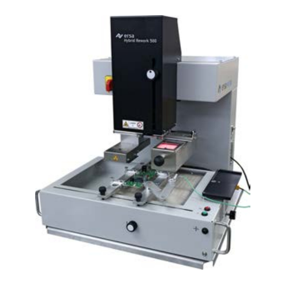
Kurtz Ersa HR 500 Translation Of The Original Operating Manual (124 pages)
Rework-System
Brand:
Kurtz Ersa
| Category:
Rework stations
| Size: 2 MB
Table of Contents
Table of Contents
3
1 Introduction
7
Product Information
8
General Information about the Product
8
Intended Use
8
Retrofitting, Changes
8
Warranty
8
Information about this Manual
9
Pictogram and Symbol Explanations
10
Prevailing Term Definitions in this Instruction Manual
11
Warnings
12
Rule Notices
13
Prohibition Notices
14
Target Readers Group
15
Copyright, Liability
15
2 Technical Data
17
Connection Data
18
Printed Circuit Boards and Components
18
General Data
18
Ambient Conditions
18
Heating System
18
Axis System
19
Cameras
19
PC System Requirements
19
3 For Your Safety
21
General Safety Instructions
22
Nationally Valid Safety and Accident Prevention Regulations
22
Fire Protection
22
Subject-Related Safety Instructions
22
Dealing with Electrical Equipment
22
Dealing with Process Materials and Substances
22
Safety Instructions for Certain Operating Phases
23
Safety Instructions for Maintenance, Service, Specific Work, Troubleshooting
23
Safety Instructions for Certain Machine and System Parts
24
Hot Device
24
Laser Equipment
24
Using a Solder Fume Extractor, Plug Available
24
Retrofitting and Changes
24
4 Transport, Installation, Storage, Disposal
25
Information Concerning Machine Transport and Storage
26
Information on How to Unpack the Machine
26
Packaging with TIP N TELL Indicator
26
Scope of Delivery
27
Available Options
27
Unpacking, Setting up and Connecting the Rework System
29
Unpacking
29
Set up
29
Remove the Transport Lock
30
Connecting the Machine
30
Assembling an RPC Camera (Optional)
33
Assembling the Accu-TC Holder and Air Deflector
35
Transporting the Rework System
36
Disposal
37
5 Commissioning
39
Setting up the PC
40
Calibrate the Pipette Distances and the Optical Axle
42
Mount the Pipette
49
6 Function Description
51
Read this First
52
Target Readers Group
52
Supplementary Documents
52
ESD-Hazardous Components
52
Overview of the Machine Parts
53
Switching on the Rework System and Starting Hrsoft 2
54
The Top Bar in the Hrsoft 2 Program
55
Temporarily Editing the Soldering Profile in the [Rework] Tab
56
Overview of the Tab [Rework]
56
Use of the Soldering Profile in the [Rework] Tabulator
58
The Tabulators [Information], [Heating Setting] and the Arrow Key [Image Processing]
59
The Three Right Tabulators
59
The [Information] Tabulator under the [Rework] Tabulator
59
The [Heating Setting] Tabulator under the [Rework] Tabulator
62
The Chart in the [Rework] Tabulator
65
The [Process Automation] Button Row
66
The [Archive] Tabulator
67
The [Show Chart] Button
68
The [User Management] Tabulator
70
Editing the Soldering Profile in the [Profile Management] Tab and Changing It Permanently
72
Overview of the [Profile Management] Tabulator
72
Create, Copy, Delete and Save Soldering Profiles in the [Profile Management] Tabulator
73
The Tabulators [Information], [Heating Setting] and the Arrow Key [Image Processing]
76
The [Information] Tabulator under the [User Management] Tabulator
76
The [Heating Setting] Tabulator under the [Profile Management] Tabulator
78
The [More] Tab under the [Profile Management] Tab / Create User
80
The Chart in the [Profile Management] Tabulator
82
The Heating Curves in the Chart in the [Profile Management] Tab
82
The [Process Automation] Buttons under the [Profile Management] Tabulator
84
The [Management] Tabulator with Three Dialog Windows
85
The Dialog [Hrsoft 2 Settings]
85
The [Chart Settings] Dialog
87
The [Device Settings] Dialog
88
The Button [Start Adjustment]
90
The Button [Manual Mode]
92
The Display and Switch Row Top Right
94
Switching off the Rework System
96
7 Tutorial - Soldering or Unsoldering a Component
98
Insert the PCB
98
Adjust the Pipette Size to the Component
99
Position a Thermocouple
100
Shielding Heat Sensitive Components
101
Activate a Soldering Profile and Prepare the Soldering Process
102
Start the Process and Work with the Assistant
103
Task 1 "Alignment
105
Task 2 "Desoldering
106
Work Step 3 "Position" and Clean the Desoldering Point
108
Task 4 "Preparation
109
Task 5 "Alignment
110
Task 6 "Inspection
112
Task 7 "Soldering
113
Task 8 "Inspection
115
Task 9 "Complete
116
Removing Residual Solder
116
8 Service and Maintenance
117
Check the Rework System on a Weekly Basis for any Dirt or Damages
118
Performing a Hrsoft 2 Update
119
9 Spare and Wear Parts
121
Read this First
122
Target Readers, Permitted Spare Parts
122
Nameplate and Machine Number
122
Spare Parts
123
Advertisement
Advertisement
Related Products
Kurtz Ersa HR 550 XL
Kurtz Ersa HR 200
Kurtz Ersa HR 600/3 P
Kurtz Ersa HR 600 XL
Kurtz Ersa HR 100 A
Kurtz Ersa HR 600/2
Kurtz Ersa 0HR200
Kurtz Ersa 0HR200-HP
Kurtz Ersa IRHP 200
Kurtz Ersa Categories
Soldering Gun
Power Tool
Rework stations
Scrubber
Measuring Instruments
More Kurtz Ersa Manuals
Login
Sign In
OR
Sign in with Facebook
Sign in with Google
Upload manual
Upload from disk
Upload from URL