
Related Manuals for Endress+Hauser Fieldgate FXA42


Summary of Contents for Endress+Hauser Fieldgate FXA42
- Page 1 Products Solutions Services BA01778S/00/EN/03.20 71483585 2020-05-15 Operating Instructions Fieldgate FXA42 System Products Gateway for data transmission via Ethernet, WLAN or mobile telecommunications...
- Page 2 • The manufacturer reserves the right to modify technical data without prior notice. Your Endress+Hauser distributor will supply you with current information and updates to these Operating Instructions. Endress+Hauser...
-
Page 3: Table Of Contents
Grid View ......Fieldgate FXA42 editor ....42 Settings . -
Page 4: About This Document
About this document Fieldgate FXA42 About this document Symbols 1.1.1 Safety symbols DANGER This symbol alerts you to a dangerous situation. Failure to avoid this situation will result in serious or fatal injury. WARNING This symbol alerts you to a dangerous situation. Failure to avoid this situation can result in serious or fatal injury. -
Page 5: Registered Trademarks
Fieldgate FXA42 About this document Registered trademarks Modbus ® Registered trademark of SCHNEIDER AUTOMATION, INC. Microsoft ® Registered trademark of the Microsoft Corporation, Redmond, Washington, USA Endress+Hauser... -
Page 6: Basic Safety Instructions
SupplyCare. In SupplyCare, the data are visualized, compiled into reports and used for other inventory management tasks. However, it is also possible to access the data transmitted by Fieldgate FXA42 without any additional software using the Web browser. Comprehensive configuration and automation capabilities are available for the Fieldgate FXA42 thanks to the integrated Web PLC. -
Page 7: Product Safety
It meets general safety standards and legal requirements. It also complies with the EU directives listed in the device-specific EU Declaration of Conformity. Endress+Hauser confirms this by affixing the CE mark to the device. Endress+Hauser... -
Page 8: Product Description
Fieldgate FXA42 Product description Information about accessories is provided in the Accessories section. Product design Four versions of the Fieldgate FXA42 are available. These versions differ in terms of the device features and data transmission technology. C / D 11 12 A0030516 ... - Page 9 Fieldgate FXA42 Product description Band 1 (2100 MHz), Band 2 (1900 MHz), Band 3 (1800 MHz), Band 4 (AWS 1700 MHz), Band 5 (850 MHz), Band 8 (900 MHz), Band 12 (700 MHz), Band 13 (700 MHz), Band 18 (800 MHz), Band 19 (800 MHz), Band 20 (800 MHz), Band 26 (850 MHz), Band 28...
-
Page 10: Incoming Acceptance And Product
• Enter the serial number on the nameplate into W@M Device Viewer (www.endress.com/deviceviewer): all the information about the gateway is displayed. • Enter the serial number on the nameplate into the Endress+Hauser Operations App or scan the 2-D matrix code (QR code) on the nameplate with the Endress+Hauser Operations App: all the information about the gateway is displayed. -
Page 11: Installation
Fieldgate FXA42 Installation Installation Installation conditions 5.1.1 Temperature and humidity Normal operation (EN 60068-2-14; Nb; 0.5 K/min): –20 to 60 °C (–4 to 140 °F) Side by side installation: –20 to 50 °C (–4 to 122 °F) Avoid condensation. Humidity (EN 60068-2-30; Db; 0.5 K/min): 5 to 85%; non-condensing 5.1.2... -
Page 12: Mounting Procedure
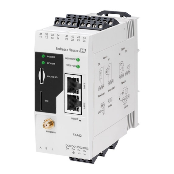
LTE Cat M1 and Cat NB1 (2G/4G) and WLAN. The antenna can be purchased as an accessory from Endress+Hauser. The antenna cable is screwed onto the connection on the front of the device. The antenna must be mounted outside the cabinet or field housing. In areas with weak reception, it is advisable to first check the communication before securing the antenna permanently. -
Page 13: Post-Installation Check
WLAN receivers Uplink to Internet or LAN via router Antenna for Fieldgate FXA42 SMA connection Fieldgate FXA42 Ethernet and WLAN Control cabinet Post-installation check • Is the DIN rail clip clicked into place? • Is the device securely seated on the DIN rail? •... -
Page 14: Electrical Connection
Electrical connection Fieldgate FXA42 Electrical connection WARNING Danger! Electric voltage! Risk of electric shock and injury from startle response. ‣ De-energize all power sources before connecting. ‣ Before commissioning the device, measure the supply voltage and compare it with the voltage specifications on the nameplate. - Page 15 Fieldgate FXA42 Electrical connection Terminal Properties Function assignment of input modules Maximum input voltage: 35 V Analog input4 to 20 mA Maximum input current: 22 mA 33 43 Internal resistance: 250 Ω (suitable for HART communication) Output voltage: 28 V...
- Page 16 Electrical connection Fieldgate FXA42 Power supply connection and digital output connection Power supply Digital output L+ L- 24VDC A0031288 12 - 24VDC A0031286 Endress+Hauser...
-
Page 17: Commissioning
Fieldgate FXA42 Commissioning Commissioning Display elements (device status indicator / LED) A0030608 Power Modem (mobile communications versions) / WLAN / Ethernet Network Web-PLC Identifier State Color Meaning Comment Power Green Power supply ON (GN) Modem Green Power supply for modem ON... -
Page 18: Preparatory Steps
• User name for the administrator: super • Password for the administrator: super • Users who do not wish to configure the Fieldgate FXA42 or who do not have the necessary authorization can log on with the following default login data. User name: eh;... - Page 19 Fieldgate FXA42 Commissioning Right-click with the mouse button to open the context menu. Select the Properties menu item. Select the Use the Following IP Address option and enter an IP address. Example of an IP address: 192.168.252.2 7. Subnet mask: enter 255.255.255.0 and press OK to confirm your entry.
- Page 20 A0030539-EN Enter the user name and password. Press OK to confirm your entry. The connection is now established and the Fieldgate FXA42 welcome screen is displayed. A0030543 The display changes automatically after a few seconds and the home screen to access the configuration menus appears.
-
Page 21: Installing The Latest Firmware
Fieldgate FXA42 Commissioning A0030547 Select the Language menu Help To change the language of the user interface, open the menu (1) in the top right-hand corner of the startup screen and select a language. To open the Help function, click the question mark icon (2). The home page and the icons in the tool bar are explained in the Help function. -
Page 22: Configuration Examples
4 x analog input 4 to 20 mA (active), 2-wire (loop powered) Measuring device power supply Once a device has been connected to the Fieldgate FXA42, the measured values are displayed in the Grid View In general, no additional configuration settings are necessary. - Page 23 Fieldgate FXA42 Commissioning Reading out the analog inputs Example 1. On the Analog inputs tab, select the desired input and edit the Settings (Tag name = name to be displayed in the application, Description = optional description, Unit = physical unit to be displayed).
- Page 24 Configuration with a digital input A0030921 4 System architecture of a Fieldgate FXA42 with a digital input SupplyCare Enterprise / SupplyCare Hosting (via Web browser) Internet / LAN SupplyCare Enterprise / SupplyCare Hosting on mobile devices (via Web browser)
- Page 25 Fieldgate FXA42 Commissioning Configuring the digital input Example 1. On the Digital inputs tab, select the desired input and edit the Settings (Tag name = name to be displayed in the application, Description = optional description). A0035081-EN 2. Click OK: ...
- Page 26 Configuration with a pulse counter A0030922 5 System architecture of a Fieldgate FXA42 with a pulse counter SupplyCare Enterprise / SupplyCare Hosting (via Web browser) Internet / LAN SupplyCare Enterprise / SupplyCare Hosting on mobile devices (via Web browser)
- Page 27 Fieldgate FXA42 Commissioning 2. Click OK: The values of the pulse counter (e.g. FXA42 Input Counter 1 and FXA42 Input Counter 1 Overflow) are displayed in the Grid View: A0035087 The configured pulse counter is now available in the editor of the Web-PLC.
- Page 28 Commissioning Fieldgate FXA42 7.5.4 Configuring the digital output The input of the digital output must be connected to an action that returns a 0 or 1. The values of the digital outputs are displayed in the Grid View: A0035089 1. Select the editor 2.
- Page 29 Communication via Modbus TCP A0034272 6 System architecture of a Fieldgate FXA42 with a HART point-to-point multiplexer SupplyCare Enterprise / SupplyCare Hosting (via Web browser) Internet / LAN SupplyCare Enterprise / SupplyCare Hosting on mobile devices (via Web browser)
- Page 30 Commissioning Fieldgate FXA42 Configuration of FXA42 as a Modbus TCP client (reading out data from other systems) The following examples show how to configure the gateway to read out data using the Modbus TCP. Please refer to the device documentation for additional information.
- Page 31 Fieldgate FXA42 Commissioning 5. Click OK: A0035104-EN 6. Restart the device The exported values are displayed in the Grid View. A0035091 Example with Datexel server module 1. Open the Settings page 2. Select the Modbus client/master tab. 3. Select Edit device and enter the data: ...
- Page 32 Commissioning Fieldgate FXA42 4. Click OK: 5. Select Edit value and enter the data. Example: pressure measuring device connected to the first channel of the Datexel server module. 6. Click OK: 7. Restart the device The exported values are displayed in the Grid View.
- Page 33 Fieldgate FXA42 Commissioning The values read in from the Datexel server module are in the microampere unit. The values in the 4 000 to 20 000 µA measuring range must be converted to the current measured value. The measuring range is linked to the measured pressure range in such a way that a certain microampere value corresponds to a defined pressure value.
- Page 34 Commissioning Fieldgate FXA42 Configuration of FXA42 as a Modbus TCP serer (transmitting data to other systems) The steps in the example below describe how to transmit data to other devices. Please refer to the device documentation for additional information. 1. Open the Settings page 2.
- Page 35 Fieldgate FXA42 Commissioning 8. Select the output: A0034401 9. Interconnect units, see the following example: A0034402 10. Save the diagram: 11. Start Web-PLC: Endress+Hauser...
- Page 36 7.5.6 Configuration with Modbus RS485 A0030923 7 System architecture of a Fieldgate FXA42 with Modbus RS485 SupplyCare Enterprise / SupplyCare Hosting (via Web browser) Internet / LAN SupplyCare Enterprise / SupplyCare Hosting on mobile devices (via Web browser) Ethernet / WLAN / UMTS / LTE Cat M1 / LTE Cat NB1...
- Page 37 Fieldgate FXA42 Commissioning 3. Under Settings, select the Enable RTU function. Enter the interval, timeout, baud rate etc.: A0035095-EN 4. Click OK: 5. Select Edit device and enter the data: A0035096-EN 6. Select Edit value and enter the data. If necessary, select the Enable limits function and enter limit values: ...
- Page 38 Commissioning Fieldgate FXA42 7. Click OK: A0035097-EN 8. Restart the device The rest of the configuration is the same as the configuration of the Modbus TCP client → 30). Configuration of FXA42 as a Modbus RS485 slave (transmitting data to other systems) 1.
- Page 39 Fieldgate FXA42 Commissioning 5. Select Edit value and enter the data: A0035100-EN 6. Click OK: A0035101-EN 7. Restart the device 8. The rest of the configuration is the same as the configuration of the Modbus TCP server → 34).
-
Page 40: Operation
Operation Fieldgate FXA42 Operation Home page The home page provides access to information on the Fieldgate FXA42, its status, inputs and outputs and various other components. A0035224-EN The home page features a tool bar with various buttons: A0040660 Closes the current page and opens the editor... - Page 41 Fieldgate FXA42 Operation A0034185 The Grid View page features a tool bar with various buttons: A0040661 Closes the current page and opens the home page Closes the current page and opens the editor Closes the current page and opens the Settings page Opens the Help The Grid View page displays all the local inputs and outputs on a clear, transparent grid.
-
Page 42: Fieldgate Fxa42 Editor
The device has a graphical editor which can be used to edit function charts – similar to the well-known continuous function charts (CFCs). Function blocks can be used to connect the inputs and outputs of the Fieldgate FXA42 and special variables. A0034194 The editor basically consists of 3 parts: •... - Page 43 Fieldgate FXA42 Operation 8.3.1 Toolbar The following screenshot shows the toolbar of the Fieldgate FXA42 editor: A0034195 The following commands can be executed with the buttons: Button Description Close the current page and open the home page. A0034196 Close the current page and open the Settings page.
- Page 44 Operation Fieldgate FXA42 Button Description Delete the selected element from the diagram view. A0034207 Open the Help. A0034184 8.3.2 Editing the diagram The function diagram consists of up to 256 units, local input and output elements (I/Os), variables and constants.
- Page 45 Fieldgate FXA42 Operation A0034212-EN To connect an input port with an output port, click one of the ports, keep the mouse button pressed, drag the blue connector that appears over the other port (see the next graphic), and release the mouse button. Note that one output port can be connected to multiple input ports.
- Page 46 Operation Fieldgate FXA42 Description of the units Unless otherwise indicated, units are processed during the processing stage of the IPO cycle . Unit Description This unit performs an addition. It adds the values of its input ports and writes the total to its output port.
- Page 47 Fieldgate FXA42 Operation Unit Description This unit performs a division. It divides the first input port by all the subsequent input ports and writes the quotient to its output port. If one of the input ports has the value 0, the output port is set to 0.
- Page 48 Operation Fieldgate FXA42 Unit Description This unit represents an on/off controller. SetOn The input ports SetOn, SetOff and Act adopt the largest numeric data type of all the output ports that SetOff are connected to one of these input ports.
- Page 49 Fieldgate FXA42 Operation Unit Description This unit packs the values of its 8 Boolean input ports into one octet and writes the octet to its 8-bit unsigned integer output port. Pack A0034290 This unit represents a proportional controller. SetHigh The input ports SetLow, SetHigh and Act adopt the largest numeric data type of all the output ports...
- Page 50 Operation Fieldgate FXA42 Unit Description This unit takes the binary value of its input port X (32-bit unsigned integer), sets the bit selected by the input port N (8-bit unsigned integer) to the state of the Boolean input port B and writes the Put Bit resulting value to its output port (32-bit unsigned integer).
- Page 51 Fieldgate FXA42 Operation Unit Description This unit can be used to limit the value of the input port In. If In is less than Min and the minimum limit is activated by the Boolean input port MinEn, the output is set to Min. If In is greater than Max and the maximum limit is activated by the Boolean input port MaxEn, the output is set to Max.
- Page 52 Operation Fieldgate FXA42 Unit Description This unit represents the state of a state machine. There are eight different state machine units (state State machine 0 to state machine 7), allowing you to implement eight independent state machines. Next0 State Machine 0...
- Page 53 Fieldgate FXA42 Operation Unit Description This unit represents a timer on-delay. The timer is started when the Boolean input port IN switches to 1. The output port ET (elapsed time, 32-bit unsigned integer) indicates how much time, in milliseconds, has elapsed since the timer was started.
- Page 54 Input and output elements (I/Os) There is one element for every input (I) and output (O). The number and structure of the I/Os depend on the specific Fieldgate FXA42 device and its configuration. Properties of the input and output elements: •...
- Page 55 Internally, the inputs/outputs are addressed via an interface index, device index, value index and, optionally, an array index. If the Fieldgate FXA42 has a number of digital inputs/outputs and a Modbus master interface, for example, the interface index will select one of these two interfaces.
- Page 56 75%. If the diagram becomes more complex, increase the PLC cycle time in the Diagram Settings. If the duty cycle is close to 100%, it is no longer possible to operate the Fieldgate FXA42. Endress+Hauser...
- Page 57 Fieldgate FXA42 Operation 8.3.5 Running the diagram Click the Start button in the toolbar to start the execution of the diagram that has been saved to the PLC. While the PLC is running, the Start button changes to the Stop button.
- Page 58 Operation Fieldgate FXA42 A0034341-EN The values are updated as quickly as possible. If the diagram is changed when Live view is active, this will cause errors to occur because the values received from the PLC will no longer match the diagram. If this happens, the Live view is stopped automatically.
-
Page 59: Settings
Fieldgate FXA42 Operation Settings You can configure your Fieldgate FXA42 on the "Settings page" (see the graphic below). A0035246-EN There is a toolbar on the Settings page. The buttons in this toolbar are described in detail in the following section. - Page 60 Click a message text to open the help and to display more detailed information about the message. Time stamps are saved in the time zone that is selected in the Fieldgate FXA42. The time zone currently selected can be either the local time zone that is saved or the time zone provided by the FIS connection if it is enabled.
- Page 61 Messages index The following section contains an index of all the messages that can be logged by the Fieldgate FXA42 components. Running the diagram • The PLC has been started. • The PLC has been stopped.
- Page 62 Operation Fieldgate FXA42 • Connection supervision failed. • Modem reset • Hanging! (state: <x>) WLAN • Started • Running • Configured IP through DHCP • Stopping driver • Stopped • Connection indication Modbus client/master • Connected to TCP device at <IP address>:<port>.
- Page 63 Fieldgate FXA42 Operation • Sending configuration to FIS • Configuration successful • FIS configuration version: <Version> • Invalid FIS authentication data. Trying again in <T> minutes. • HTTP error <HTTP-Error> occurred while sending FIS registration message. Trying again in <T> minutes.
- Page 64 Operation Fieldgate FXA42 DHCP server • Running • Added static lease IP=<x>, MAC=<y> • Discover message received, CI=<x>, MAC=<y> • Request message received, CI=<x>, MAC=<y> • Leased IP=<x>, Leasing Time=<y>, Index=<z> • Release message received, CI=<x>, MAC=<y> • Release IP=<x>, Index=<y>...
- Page 65 • RTOS version is not supported. Version (<version number>) is required. • Device is secured with the default password, please change it. • Fatal error: <error message> 8.4.2 Login You can configure the login data for the Fieldgate FXA42 on this page. Endress+Hauser...
- Page 66 Press and hold the reset button. The reset button can be accessed through a small hole in the front. ‣ Switch on the Fieldgate FXA42. Keep the reset button pressed while the device is booting until the Web-PLC LED flashes twice. The factory settings are restored. 8.4.3 Network General network settings can be configured on this page.
- Page 67 Fieldgate FXA42 Operation Device name The device name is registered as a NetBIOS name. Within the local network, the name of the device - instead of the IP address - can be used to access the device. In addition to the configurable name, another name built from the prefix MAC and the MAC-ID of the device (e.g.
- Page 68 Operation Fieldgate FXA42 The source code used is based on documentation and code examples by Christopher R. Hertel. Project website: ubiqx.org/cifs License: LGPL 8.4.4 Cellular modem The cellular modem can be enabled and configured on this page. To enable the cellular modem, tick the check box beside Enable cellular modem and enter the PIN of the SIM card.
- Page 69 Fieldgate FXA42 Operation Connection supervision The connection supervision will try to connect to the first URL whenever there has been no payload traffic for the period of time indicated. The period can be specified between 60 and 60000 seconds. If the connection to the first URL fails, the second URL will be tried. If the second URL also fails the cellular modem connection will be re-established.
- Page 70 Operation Fieldgate FXA42 Deactivated The cellular modem driver has been temporarily deactivated. Activated The cellular modem driver has been re-activated after temporary deactivation. Powered modem The supply voltage for the cellular modem hardware has been switched on. Modem initialized (RSSI: <x> dBm) The cellular modem has been successfully initialized.
- Page 71 Fieldgate FXA42 Operation Code Description -105 A reply from the cellular modem hardware was too long. -134 The cellular modem hardware is invalid. Contact customer support if an error code is displayed that is not on the above list. Network registration timed out ((not) searching) No cellular network could be found within a reasonable time.
- Page 72 Operation Fieldgate FXA42 Code Description An invalid IP configuration was received from the provider. No PPP connection could be established. Contact customer support if an error code is displayed that is not on the above list. Network lost (code <x>, network status <y>) The cellular modem lost the connection to the network.
- Page 73 Fieldgate FXA42 Operation The connection supervision has failed to connect to the configured URLs. The connection will be closed. Modem reset The cellular modem hardware has been reset. Hanging! (state: <x>) The cellular modem driver is in an invalid state.
- Page 74 Operation Fieldgate FXA42 The WLAN unit driver is being stopped. Stopped The WLAN unit driver has been stopped. Connection indication Message Description NOT CONNECTED No specific indication. ASSOCIATED Success, unit is associated (infrastructure mode). MGMT_ERROR Internal protocol error occurred (the unit restarts).
- Page 75 Fieldgate FXA42 Operation Devices and values The Modbus Client/Master list shows the Modbus devices and their values. Devices and values (input or output) can be added, edited, deleted or cloned via the buttons below the list. For each device and value the list shows a name, the communication parameter and an index.
- Page 76 Operation Fieldgate FXA42 Settings The following settings can be made in the fields below the live list: Setting Description Interval Defines the interval (in milliseconds) in which all Modbus values are read or written. If a warning message appears in the event log, the interval is too short to read or write all the values.
- Page 77 Fieldgate FXA42 Operation Error code Description Could not open TCP socket. Could not switch TCP socket to blocking mode. Unable to establish the TCP connection. Setting options on TCP socket failed. Contact customer support if an error code is displayed that is not listed here.
- Page 78 Operation Fieldgate FXA42 Read illegal floating point value from RTU device <device address> (function code: <function code>, address: <value address>, quantity: <quantity>) The driver read an illegal floating point value from the Modbus RTU slave with the address indicated. This value is identified by the Modbus function code used to read it, its address (starting from 0) and the quantity of registers or coils.
- Page 79 Fieldgate FXA42 Operation Parameters Description Number Number of registers or coils to read or write. If more registers or coils are read or written than fit into the selected data type, the value will become an array. For more information on the number of registers or coils, see the Limits section.
- Page 80 Operation Fieldgate FXA42 Contact customer support if an error code is displayed that is not listed here. 8.4.8 Analog inputs The analog inputs of the device can be configured on this page. On the left side of the page the user may select one of the 4 different inputs by clicking the corresponding tab. The settings for each of the 4 inputs are identical.
- Page 81 8.4.9 Digital inputs The digital inputs of the Fieldgate FXA42 can be configured on this page. On the left side of the page the user may select one of the 4 different inputs by clicking the corresponding tab. The settings for each of the 4 inputs are identical.
- Page 82 Operation Fieldgate FXA42 Digital inputs settings In this section the user may configure the settings for each digital input. The following settings are available: Settings Description Identifier The label name of the input. Description A text describing the input' s function.
- Page 83 Fieldgate FXA42 Operation The following settings apply to all I/Os for which data transmission is enabled: • Data transmission interval: The interval in which the recorded data is to be transmitted. Example: A value of 2 hours transmits the data at 00:00, 02:00, 04:00, 06:00 etc.
- Page 84 Operation Fieldgate FXA42 Upload file(s) This section can be used to upload certificate files for encrypted SMTP and FTP connections. DER certificates can be used. The DER format is a binary certificate format. The file names of the DER certificate files mostly end with .cer or .der.
- Page 85 Fieldgate FXA42 Operation If the registration fails, the device will make another attempt after <T> minutes. <T> is the next number of the Fibonacci sequence starting from 1. The maximum number of minutes between 2 attempts is 1440. Configuration exchange The device is able to transmit its current configuration to the FIS in the form of a *.cup...
- Page 86 Operation Fieldgate FXA42 Up to five different e-mail recipients can be defined. An individual text can be defined for each recipient. In addition, the user can specify what type of information the recipient should receive (measured values, limit alarms, NAMUR alarms).
- Page 87 Fieldgate FXA42 Operation The following settings are available: Settings Description Enable SMS Enable/disable the SMS functionality SMS confirmation This setting defines the way that the Alarm SMS messages should be acknowledged so that the SMS escalation stops. There are 3 possible SMS confirmation options: •...
- Page 88 Operation Fieldgate FXA42 Sent measurements file to FTP server An FTP message was sent to the server. Messages relating to the FIS registration and configuration are created by the I/O Task of the device. Sending FIS registration message A registration message is being transmitted to the FIS server.
- Page 89 Fieldgate FXA42 Operation 8.4.12 System time The system time can be configured on this page. It is also possible to configure whether and how the system time should be synchronized via the Simple Network Time Protocol (SNTP) or FIS. If FIS is activated on the Messages page, the system uses FIS communication to set the time.
- Page 90 Operation Fieldgate FXA42 System clock updated from RTC The system clock has just been updated with the time from the real-time clock. Could not get exclusive access to clock(s). The system time manager could not get exclusive access to the system clock and (if available) the real-time clock.
- Page 91 Fieldgate FXA42 Operation 8.4.13 OpenVPN The firmware of the device includes OpenVPN. The device can be integrated into a virtual private network with OpenVPN. There are 2 ways to start OpenVPN. OpenVPN can either be executed automatically at system start-up or be started manually via the portal. The device has a portal node at the address.
- Page 92 Operation Fieldgate FXA42 The OpenVPN driver has been successfully stopped. Driver stopped. The OpenVPN driver has exited. Connection established. An OpenVPN connection has been established. Connection closed. An OpenVPN connection has been closed. Authority's certificate uploaded. The certification authority' s certificate file (ca.crt) has been successfully uploaded.
- Page 93 Fieldgate FXA42 Operation OpenSSL OpenSSL is used in OpenVPN. Project website: www.openssl.org License: OpenSSL license OpenVPN "OpenVPN" is a trademark of OpenVPN Technologies, Inc. Project website: openvpn.net License: OpenVPN licence 8.4.14 DHCP server The device' s firmware features a Dynamic Host Configuration Protocol (DHCP) server which can be enabled and configured on this page.
- Page 94 Operation Fieldgate FXA42 Discover message received, CI=<x>, MAC=<y> A DHCP discover message was received from a client. The message also shows the client identifier as a hex string and the client' s MAC address. Request message received, CI=<x>, MAC=<y> A DHCP request message was received from a client. The message also shows the client identifier as a hex string and the client' s MAC address.
- Page 95 This feature can be used, for example, to give another device in the local network access to the gateway' s cellular modem Internet connection (global network). The device must be connected to the Ethernet interface of the Fieldgate FXA42 for this purpose. The following operations can be performed here: •...
- Page 96 Static mappings are used to make a local device' s services accessible from the global network under the global IP address of the Fieldgate FXA42. Up to 10 static mappings can be configured. You have to configure the following options for each mapping:...
- Page 97 Fieldgate FXA42 Operation The firewall of the device has a blocking policy. This means that while outgoing connections are generally allowed, incoming connections will be generally blocked. Only specific incoming connections are allowed if there is a rule allowing the connection.
- Page 98 Operation Fieldgate FXA42 Minimum/maximum port These parameters only appear if the Other option is selected under Service. They determine the port(s) that run the service that should be allowed. A single port (set minimum and maximum port to the same value) or a port range (e.g.
- Page 99 The SD card included in the delivery is already formatted. To be able to update the firmware of the Fieldgate FXA42, an SD card (card type: microSD) formatted by the device itself must be provided. The SD card is formatted with the Power- Loss-Protection (PLP) format.
- Page 100 Prerequisites for a FIS update 1. Insert an SD card in the slot of the device. The SD card must have been formatted beforehand by the Fieldgate FXA42. An SD card with sufficient free space is required to download and unpack *.cup files.
- Page 101 Fieldgate FXA42 Operation NOTICE A complete device failure can occur if a live update process is interrupted. If this happens, the device then does not transmit any more data and can no longer be configured. ‣ Pay attention to the warning information on the Update screen of the user interface of the device.
- Page 102 Operation Fieldgate FXA42 Project website: www.libarchive.org License: New BSD license zlib zlib is used to extract update packages. Project website: www.zlib.net License: zlib license 8.4.18 Export The configuration of your device can be exported on this page. A update package is created that can be used for other devices of the same type. To apply the exported packet to a second device, use the Update page.
-
Page 103: Event Log Messages At System Start-Up
Fieldgate FXA42 Operation Open-source software The following open-source software has been used to implement the export functionality: libarchive libarchive is used to create update packages. Project website: www.libarchive.org License: New BSD license zlib zlib is used to compress update packages. - Page 104 Operation Fieldgate FXA42 The COM server has been successfully initialized. Diagram loaded A diagram has been successfully loaded. Web configuration modules initialized The web configuration modules, which accept the configuration data from the Settings page, have been successfully initialized. Update exporter module initialized The update exporter module, which exports the configuration to an update package, has been successfully initialized.
- Page 105 The driver for the second Ethernet interface could not be started. Unsupported Ethernet (1) interface type. (<interface type>) The Fieldgate FXA42 firmware could not find a driver for the second Ethernet interface. The message also shows the numerical Ethernet interface type.
-
Page 106: Dojo Toolkit
Operation Fieldgate FXA42 The cycle time of the PLC task has been violated, i.e. the task was still busy with the previous IPO cycle when it was supposed to the next IPO cycle. Could not start update from external medium. -
Page 107: Diagnostics And Troubleshooting
The reset button (→ 8) can be accessed through a small hole in the front. 1. Switch off the Fieldgate FXA42 (switch off the supply voltage). 2. Press and hold the reset button. 3. Switch on the Fieldgate FXA42. Keep the reset button pressed during the booting procedure. The factory settings are restored. - Page 108 Maintenance Fieldgate FXA42 CAUTION Danger from electric voltage when cleaning with water. Risk of electric shock and injury from startle response. ‣ Do not clean the device with water. Endress+Hauser...
-
Page 109: Repair
The device must be returned if the wrong device has been ordered or delivered. As an ISO-certified company and also due to legal regulations, Endress+Hauser is obliged to follow certain procedures when handling any returned products that have been in contact with medium. -
Page 110: Accessories
Inventory management software that displays the level, volume, mass, temperature, pressure, density or other parameters of tanks. The parameters are recorded and transmitted by means of gateways like Fieldgate FXA42, Connect Sensor FXA30B or other gateway types. This Web-based software is installed on a local server and can also be visualized and operated with mobile terminals such as a smartphone or tablet. -
Page 111: Technical Data
Fieldgate FXA42 Technical data Technical data 13.1 Input 13.1.1 Terminal assignment Analog In Digital In l In it a D ig g In a lo u t: it a D ig -2 4 p ly R i= Power Supply: Modbus RS485:... - Page 112 Technical data Fieldgate FXA42 X1 = 11 21 31 41 4 x GND X3 = 13 23 33 43 4 x 4 to 20 mA analog input Maximum input voltage: 35 V Maximum input current: 22 mA Internal resistance: 250 Ω (suitable for...
-
Page 113: Output
Fieldgate FXA42 Technical data X2 = 12 22 32 42 4 x digital input Input voltage L: < 5 V Input voltage H: > 11 V Input current: < 5 mA Maximum input voltage: 35 V X4 = 14 24 34 44 4 x auxiliary voltage output to control... -
Page 114: Environment
Technical data Fieldgate FXA42 12 to 24 V D+ D+ D– D– 12 to 24 V Power supply for digital output You may only use power units that ensure safe electrical isolation according to DIN VDE 0570-2-6 and EN61558-2-6 (SELV / PELV or NEC Class 2) and that are designed as limited-energy circuits. -
Page 115: Certificates And Approvals
Fieldgate FXA42 Technical data 13.3.6 Installation height as per IEC61010-1 Ed.3 Generally up to 2 000 m (6 560 ft) above sea level 13.3.7 Degree of protection IP20, NEMA1 13.3.8 Shock resistance DIN EN 60068-2-27: ±15 g; 11 ms 13.3.9 Vibration resistance EN 60068-2-64 / IEC60068-2-64: 20..2000 Hz 0.01 g... - Page 116 Modifications The FCC requires the user to be notified that any changes or modifications made to this device that are not expressly approved by Endress+Hauser may void the user' s authority to operate the equipment. Federal Communications Commission Statement This device complies with Part 15 of the FCC rules.
-
Page 117: Index
Fieldgate FXA42 Index Index Application ....... . . 6 CE mark (declaration of conformity) ....7 Cleaning . - Page 118 *71483585* 71483585 www.addresses.endress.com...
Need help?
Do you have a question about the Fieldgate FXA42 and is the answer not in the manual?
Questions and answers