Table of Contents
Advertisement
Advertisement
Table of Contents

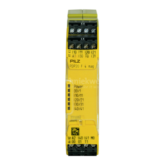
Summary of Contents for Pilz PDP20 F 4 mag
- Page 1 PDP20 F 4 mag Decentralised periphery Operating Manual-24737-EN-03...
- Page 2 Preface This document is a translation of the original document. All rights to this documentation are reserved by Pilz GmbH & Co. KG. Copies may be made for internal purposes. Suggestions and comments for improving this documentation will be gratefully received.
-
Page 3: Table Of Contents
Block diagram Function description Timing diagram Installation Wiring Permitted sensors from Pilz Preparing for operation Operation Status indicator Fault indicator Technical details Safety characteristic data Order reference Product Accessories EC Declaration of Conformity Operating Manual PDP20 F 4 mag 24737-EN-03... -
Page 4: Introduction
PDP20 F 4 mag Introduction Validity of documentation This documentation is valid for the product PDP20 F 4 mag. It is valid until new documenta- tion is published. This operating manual explains the function and operation, describes the installation and provides guidelines on how to connect the product. -
Page 5: Safety
Intended use The sensor interface PDP20 F 4 mag enables up to 4 sensors to be connected in series. Permitted sensors are sensors with a N/O / N/O combination and the Pilz sensors listed in the section entitled "Permitted sensors from Pilz". The sensor interface meets the requirements in accordance with:... -
Page 6: Use Of Qualified Personnel
Note for overvoltage category III: If voltages higher than low voltage (>50 VAC or >120 VDC) are present on the unit, connected control elements and sensors must have a rated insulation voltage of at least 250 V. Operating Manual PDP20 F 4 mag 24737-EN-03... -
Page 7: Unit Features
There is a high signal at safety outputs O0, O1 when all the input circuits I10 ... I41 are closed. If at least one of the input circuits is open or a sensor is partially operated, the safety outputs will switch to a low signal. Operating Manual PDP20 F 4 mag 24737-EN-03... -
Page 8: Timing Diagram
The safety outputs of a PDP20 F 4 mag may be connected to the cascading inputs I40 - I41 on another PDP20 F 4 mag. 3 additional sensors may be AND-linked via this device. In the event of a short across the contacts, the safety outputs will be switched off safely (low sig- nal). -
Page 9: Installation
Permitted sensors from Pilz PSENmag: – PSEN 1.1p-10, PSEN 1.1p-20 – PSEN ma1.3-20 M12, PSEN ma1.3a-20, PSEN ma1.3b-20, PSEN ma1.3b-23, PSEN ma1.3n-20, PSEN ma1.3p-20 – PSEN ma1.4-51 M12, PSEN ma1.4a-50, PSEN ma1.4a-51, PSEN ma1.4n-50, PSEN ma1.4n-51, PSEN ma1.4p-50, PSEN ma1.4p-51 PSENhinge – PSEN hs1.1p – PSEN hs1.2p PSENrope – PSEN rs1.0 – PSEN rs2.0 Operating Manual PDP20 F 4 mag 24737-EN-03... -
Page 10: Preparing For Operation
– The test pulses are permanently assigned to the inputs (T0 to I10, I20, I30, I40 and T1 to I11, I21, I31, I41) and must be connected as shown in the wiring diagram. – Unused inputs must also be connected to the assigned test pulse. Operating Manual PDP20 F 4 mag 24737-EN-03... -
Page 11: Operation
When the supply voltage is applied, the device checks whether the device is operating as a stand-alone device or in series with another PDP20 F 4 mag. The unit is ready for operation when the Power LED is permanently lit. Operating Manual PDP20 F 4 mag 24737-EN-03... -
Page 12: Status Indicator
Remedy: Switch off supply voltage, rectify the fault and then switch the supply voltage back on again. I10/11 or I20/21 or I30/31 or I40/41 Input circuit is partially operated Remedy: Open input circuit and close both N/O contacts again. Operating Manual PDP20 F 4 mag 24737-EN-03... -
Page 13: Technical Details
Number of test pulse outputs Voltage, test pulse outputs 24 V DC Relay outputs AgCdO Contact material Times Switch-on delay Typ. switch-on delay 500 ms Recovery time at max. switching frequency 1/s After power failure 40 ms Operating Manual PDP20 F 4 mag 24737-EN-03... - Page 14 0,5 Nm Conductor cross section with spring-loaded terminals: 0,2 - 2,5 mm², 24 - 12 AWG Flexible with/without crimp connector Spring-loaded terminals: Terminal points per connec- tion 9 mm Stripping length with spring-loaded terminals Operating Manual PDP20 F 4 mag 24737-EN-03...
-
Page 15: Safety Characteristic Data
Order no. PDP20 F 4 mag Sensor interface 773 310 Accessories Product type Features Order no. Set spring terminals 1 set of spring-loaded terminals 751 004 Set screw terminals 1 set of screw terminals 750 004 Operating Manual PDP20 F 4 mag 24737-EN-03... -
Page 16: Ec Declaration Of Conformity
European Parliament and of the Council. The complete EC Declaration of Conformity is available on the Internet at www.pilz.com/downloads. Representative: Norbert Fröhlich, Pilz GmbH & Co. KG, Felix-Wankel-Str. 2, 73760 Ost- fildern, Germany Operating Manual PDP20 F 4 mag... - Page 17 Back cover Support Technical support is available from Pilz round the clock. Americas Australia Scandinavia Brazil +61 3 95600621 +45 74436332 +55 11 97569-2804 Spain Canada Europe +34 938497433 +1 888-315-PILZ (315-7459) Austria Switzerland +41 62 88979-30 Mexico +43 1 7986263-0...


Need help?
Do you have a question about the PDP20 F 4 mag and is the answer not in the manual?
Questions and answers