Maico AKE 150 Mounting And Operating Instructions
Automatic cellar dehumidification
Hide thumbs
Also See for AKE 150:
- Installation and operating instructions manual (40 pages) ,
- Safety instruction (6 pages)
Table of Contents
Advertisement
Available languages
Available languages
Quick Links
Advertisement
Chapters
Table of Contents

Related Manuals for Maico AKE 150


Summary of Contents for Maico AKE 150
- Page 1 Automatic cellar dehumidification Notice de montage et mode d'emploi Déshumidification automatique des caves AKE 150 w w w . m a i c o - v e n t i l a t o r e n . c o m...
-
Page 2: Table Of Contents
6. Sicherheitshinweise ......... 6 7. Montagevorbereitungen ......7 7.1 Wand ..........7 7.2 Decke ..........7 7.3 Rohr ..........7 Impressum: © Maico Elektroapparate-Fabrik GmbH. Deutsche Original-Montageanleitung. Druckfehler, 7.4 Außenabdeckung ......7 Irrtümer und technische Änderungen vorbehalten 7.5 Ventilator ........... 8... -
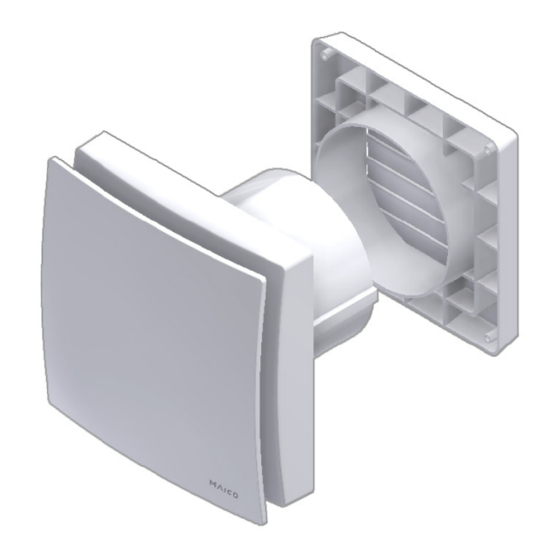
Page 3: Lieferumfang
Gebrauch gut auf. 12 Außenverschlussklappe 2.1 Installationspersonal 3.2 Produktbeschreibung Montage nur durch Fachkräfte zulässig. AKE 150 ist ein Kleinraumventilator zum Der elektrische Anschluss darf nur von Entfeuchten von Räumen, insbesondere Elektrofachkräften vorgenommen werden. Kellern und ähnlicher Nebenräume. Das Diese besitzen eine elektrotechnische Aus- Gerät besitzt ein feststehendes Innengitter und... - Page 4 LED 2 bestätigt. Referenzwert festlegen Taster 1 Frostschutz: Manuelles Lüften Taster 2 Um ein Auskühlen des Raumes zu vermeiden, besitzt die AKE 150 eine Betriebsart LED 1 Frostschutzfunktion. Hierbei schaltet Ventilatorstatus LED 2 sich der Ventilator bei Rauminnen- temperaturen von weniger als 5°C automatisch ab.
-
Page 5: Bestimmungsgemäße Verwendung
3. Produktinformationen │ DE Manuelles Lüften – Taster 2: 3.3 Bestimmungsgemäße Verwendung Die AKE 150 schaltet den Ventilator ● Dieses Gerät ist ausschließlich für den vollautomatisch und bedarfsoptimiert ein Hausgebrauch und ähnliche Zwecke und aus. vorgesehen. Im Auszustand kann der Ventilator ●... -
Page 6: Umgebungsbedingungen Und Grenzen Für Den Betrieb
DE │ 4. Umgebungsbedingungen und Grenzen für den Betrieb ● Keine Veränderungen am 4. Umgebungsbedingungen und Gerät vornehmen. Grenzen für den Betrieb ● Gerät nie ohne Elektronik- ● Zulässige Höchsttemperatur des Förder- abdeckung [7] und mediums + 40 °C. ● Bei Betrieb mit raumluftabhängigen Abdeckung [4] betreiben. -
Page 7: Montagevorbereitungen
6. Sicherheitshinweise │ DE 2. Wanddurchbruch anbringen oder Kernloch Zuluftnachströmung bohren: Mindestdurchmesser 150 mm. innerhalb der Wohnung Empfehlung: Wandhülse WH 150 ● Die Luftführung in der einbauen. Wanddurchbruch mit Mindestdurchmesser 170 mm Wohnung muss so erfolgen, anbringen. dass möglichst keine Luft aus 3. -
Page 8: Ventilator
DE │ 7. Montagevorbereitungen 1. Außenverschlussklappe [12] mit Außen- Klimasensor auspacken [11]. Das Sensorverbindungskabel nicht vom Außen-Klimasensor lösen, es wird durch das Rohr mit dem Ventilator während des Gehäuseeinbaus verbunden. 2. Sensorkabel in den Stutzen einlegen. 3. Beigefügtes Dichtband am Stutzen mittig anbringen. -
Page 9: Montage
8. Montage ‒ Gehäuseeinbau│ DE 4. Leitungstülle [9] vorsichtig aus dem 8. Montage Gehäuse drücken und herausnehmen. Alternativ bei elektrischem Aufputz- Bei Einbau in quadratischen Wand- anschluss Leitungstülle [9] im Gehäuse hülsen Distanzrahmen ECA15- belassen und Leitungstülle [10] aus dem EMA16 verwenden ... -
Page 10: Elektrischer Anschluss
DE │ 8. Montage ‒ Elektrischer Anschluss 3. Sitz der Leitungstülle [9] kontrollieren. Diese muss gut abdichten. 8.4 Endmontage Vor Anbringen der Elektronikab- deckung die Lage des Sensorverbindungskabels vom Außen-Klimasensor prüfen, damit diese nicht die Montage des Innen- Klimasensors blockiert. 7. -
Page 11: Inbetriebnahme
8. Montage ‒ Inbetriebnahme │ DE 2. Den mitgelieferten Innen-Klimasensor [6] 1. Innenteile des Ventilators nur mit einem lagerichtig ( Pfeile ) in den Anschluss- trockenen Tuch reinigen. sockel einstecken. 2. Bei stark verunreinigter Designabdeckung 3. Abdeckung [4] anbringen. [3] diese gleichmäßig parallel von Abdeckung [4] abziehen und mit Wasser reinigen. -
Page 12: Demontage
De │ 12. Demontage 12. Demontage 13. Entsorgung Die Demontage darf nur von einer Nicht in den Restmüll. Elektrofachkraft vorgenommen Das Gerät enthält teils wiederver- werden. wertbare Stoffe, teils Substanzen, die nicht in den Restmüll gelangen dürfen. Lebensgefahr durch Strom- schlag. - Page 13 7. Installation preparations ......18 7.1 Wall ..........18 Acknowledgements 7.2 Ceiling ..........18 © Maico Elektroapparate-Fabrik GmbH. This instruct- tion is a translation of the German original operating 7.3 Duct ..........18 instructions. We cannot be held responsible for mis- 7.4 External cover .........
-
Page 14: Scope Of Delivery
Mounting is only permitted when carried out by trained specialists. 3.2 Product description Only qualified electricians are permitted to AKE 150 is a small room fan for dehumidi- make the electrical connections. They are fying rooms, especially cellars and other trained in electrical engineering and are similar rooms. - Page 15 LED 1: Blinking* Manual ventilation – Button 2: LED 1: Blinks Frost protection The AKE 150 switches the fan on and off twice with long automatically and in a manner optimised to pause demand. When off, the fan can be switched...
-
Page 16: Intended Use
3.4 Predictable misuse exist in this case. Maico is not liable for damages caused by improper use (use other than intended use). Manual ventilation is also possible Under no circumstances should the unit... -
Page 17: Safety Instructions
Safe and correct practices supply air cross section of at during operation least 150 cm², e.g. with Maico Danger of injury caused door ventilation grille MLK. by objects in the impeller. Do not insert any objects... -
Page 18: Installation Preparations
UK │ 7. Installation preparations 7.4 External cover 7. Installation preparations 7.1 Wall The prescribed minimum distances between the wall and the ceiling shown in the figure must be observed. 1. Unpack the external shutter [12] with external climate sensor [11]. Do not remove the sensor connec- tion cable from the external climate sensor. -
Page 19: Mounting
7. Installation preparations │ UK 8. Mounting For installation in square wall sleeves, use ECA15-EMA16 spacing frames associated mounting instructions. 8.1 Installation of external shutter with outdoor climate sensor 1. Guide sensor connection cable [11] through the wall breakthrough/wall sleeve and pull it through to the other side of the 2. -
Page 20: Electrical Connection
UK │ 8. Mounting ‒ Electrical connection 4. Push cable grommet [9] carefully out of housing and remove it. Alternatively, with an electrical surface-mounted connection, leave cable grommet [9] in the housing and take cable grommet [10] out of the housing. -
Page 21: Final Assembly
8. Mounting ‒ Final assembly │ UK 3. Check position of cable grommet [9]. It 2. Insert the supplied internal climate sensor must be well sealed. [6] correctly ( arrow X) in the connector sockets. 3. Fit cover [4]. 8.4 Final assembly Before fitting the electronics cover, 8.5 Start-up check the location of the external... -
Page 22: Fault Rectification
UK │ 10. Cleaning 1. Only use a dry cloth to clean the internal 12. Dismantling parts of the fan. Dismantling may only be undertaken 2. If the designer cover [3] is very dirty, by an electrician. evenly remove it in parallel from the cover [4] and clean with water. - Page 23 7.1 Mur............28 7.2 Plafond ..........28 7.3 Gaine ronde ......... 29 Mentions légales © Maico Elektroapparate Fabrik GmbH. Cette instruc- 7.4 Protection externe ........ 29 tion est une traduction de l'instruction allemande 7.5 Ventilateur ..........29 originale. Sous réserve de fautes d'impression,...
-
Page 24: Volume De Fourniture
12 Volet de fermeture extérieur 2.1 Personnel d'installation 3.2 Description du produit Montage exclusivement réservé aux AKE 150 est un aérateur pour petite pièce professionnels. servant notamment à déshumidifier les caves Le branchement électrique doit et locaux similaires. Cet appareil possède exclusivement être réalisé... - Page 25 Élimination des dysfonctionnements. Déshumidification accomplie – bouton 1/ clignotement LED 2 : Avec le clignotement de la LED 2, l'AKE 150 signale que la déshumidification a réussi et se solde par une réduction de l'humidité de la pièce d'au moins 0,2 g/m par rapport à...
-
Page 26: Utilisation Conforme
Protection contre l'air sec : pour des Endommagement de la ATTENTION raisons sanitaires et d'efficacité énergé- substance du bâtiment par tique, l'AKE 150 est équipé d'une fonction ventilation manuelle. de protection contre l'air sec. Cette fonction Une ventilation manuelle trop de protection arrête le ventilateur dès longue risque, dans un environ- qu'une humidité... -
Page 27: Erreurs D'application Prévisibles
3. Informations produit │ FR ● Brancher exclusivement 3.4 Erreurs d'application prévisibles l'appareil sur une installation Maico décline toute responsabilité en cas de dommages découlant d'une utilisation non électrique permanente avec conforme. Ne jamais utiliser l'appareil : des câbles de type NYM-O ●... -
Page 28: Préparatifs De Montage
110 mm du mur. propager dans les pièces dans lesquelles l'AKE 150 7.2 Plafond est installé. Risque de court-circuit et ATTENTION d'endommagement de ●... -
Page 29: Gaine Ronde
4. Poser le ruban isolant fourni au centre de la tubulure. la tubulure. 7.5 Ventilateur Sur le modèle AKE 150, poser 1. Déballer l'appareil et retirer le cache de impérativement le ruban isolant protection [3]/[4]. Pour détacher le cache pour que les appareils n'aspirent pas de protection, déverrouiller les crochets... -
Page 30: Montage
FR │ 8. Montage 3. Déposer le boîtier [1], percer les orifices 8. Montage des chevilles M6 de Ø 6 mm et y introduire les chevilles. Utiliser le cadre d'entretoise ECA15- EMA16 lors du montage dans des 4. Pousser avec précaution le manchon de gaines murales carrées ... -
Page 31: Branchement Électrique
8. Montage ‒ Branchement électrique │ FR 6. Introduire le câble de raccordement du détecteur d'atmosphère extérieure [11] dans l'orifice ( flèche) du boîtier de ventilateur [1] prévu à cet effet. 3. Contrôler l'assise du manchon de câble [9] qui doit assurer une bonne étanchéité. 8.4 Montage final Avant de poser le cache électronique, contrôler la position du... -
Page 32: Mise En Service
FR │ 8. Montage ‒ Montage final 1. Enfoncer les 3 ergots du cache électro- 9. Entretien nique [7] dans les échancrures I, II et III du boîtier jusqu'à enclenchement. Ce L'appareil ne nécessite aucun entretien. faisant, enfoncer fermement le cache électronique dans le boîtier aux positions des flèches. -
Page 33: Élimination Des Dysfonctionnements
11. Élimination des dysfonctionnements│ FR 11. Élimination des 12. Démontage dysfonctionnements Seul un électricien qualifié peut se charger du démontage. ● Lors de tout dysfonctionnement, consulter un électricien qualifié. ● Les réparations sont exclusivement Danger de mort par électrocution ! réservées à... -
Page 34: Schéma De Branchement
DE │ UK │ FR │ 14. Schaltbild, Wiring diagram, Schéma de branchement 14. Schaltbild, Wiring diagram, Schéma de branchement AKE 150 Entfeuchtungssteuerung Dehumidification control Commande de déshumidification Optionaler Taster für manuelles Lüften Optional button for manual ventilation Bouton en option pour la ventilation manuelle Anschluss für optionales Zuluftelement,... - Page 36 Maico Elektroapparate-Fabrik GmbH • Steinbeisstr. 20 • 78056 Villingen-Schwenningen • Germany • Service +49 7720 6940 • technik@maico.de...
Need help?
Do you have a question about the AKE 150 and is the answer not in the manual?
Questions and answers