Advertisement
Available languages
Available languages
Quick Links
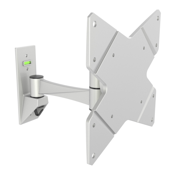
Wandhalterung für TV / Monitor
Bitte überprüfen Sie VOR der Montage den Lochabstand zwischen den Befestigungslöchern an Ihrem Bildschirm!
!
Diese Wandhalterung unterstützt folgende Lochabstände:
Horizontal / Waagerecht
Vertikal / Senkrecht
S1622
VESA-Befestigungslöcher
Vertikal /
Senkrecht
Horizontal / Waagerecht
75mm, 100mm, 200mm
75mm, 100mm, 200mm
75x75
100x100
200x100
200x200
MONTAGEANLEITUNG
ACHTUNG: NIEMALS DAS MAXIMAL
ZULÄSSIGE BELASTUNGSGEWICHT
ÜBERSCHREITEN. MISSACHTUNG
KANN ZU SACHSCHÄDEN ODER
SCHWEREN VERLETZUNGEN FÜHREN!
Bildschirm Rückseite
20kg
(44lbs)
MAX
Deutsch
v.16.4-1
English
Advertisement

Related Manuals for ricoo S1622


Summary of Contents for ricoo S1622
- Page 1 Bitte überprüfen Sie VOR der Montage den Lochabstand zwischen den Befestigungslöchern an Ihrem Bildschirm! VESA-Befestigungslöcher Vertikal / Senkrecht Horizontal / Waagerecht Bildschirm Rückseite Diese Wandhalterung unterstützt folgende Lochabstände: 75mm, 100mm, 200mm Horizontal / Waagerecht 75mm, 100mm, 200mm Vertikal / Senkrecht 20kg 75x75 S1622 100x100 (44lbs) 200x100 200x200 Deutsch English...
- Page 2 ACHTUNG: Lesen Sie die gesamte Bedienungsanleitung durch, bevor Sie mit der Montage beginnen. WARNUNG • Beginnen Sie nicht mit der Montage, bis Sie alle Anweisungen und Warnungen, welche in dieser Montageanleitung vorhanden sind, durchgelesen und verstanden haben. Wenn Sie Fragen zu den Anweisungen oder Warnungen haben, kontaktieren Sie bitte Ihren Händler. •...
- Page 3 Lieferumfang WICHTIG: Stellen Sie vor der Montage sicher, dass alle Teile welche hier aufgeführt sind, bei der Lieferung dabei sind. Sollten Teile fehlen oder defekt sein, kontaktieren Sie Ihren Händler. 4mm Inbusschlüssel (x1) 3mm Inbusschlüssel (x1) Kabel-Clip (x2) M4x14 (x2) Grundgerüst (x1) Paket M M4x14 (x4)
- Page 4 1. Trennung der Frontplatte vom Grundgerüst 2a. Befestigung an der Holzbalkenwand 50mm (2") ø 4mm (ø 5/32”) Holzbalken mit Balkenfinder Montagelöcher finden und die Montagelöcher bohren. markieren. Wandplatte an die Wand anschrauben. WARNUNG • Stellen Sie sicher, dass die Befestigungsschrauben in der Mitte der Balken verankert sind. Die Verwendung eines Balkenfinders wird dringend empfohlen.
- Page 5 2b. Befestigung an der Massivbetonwand 55mm 60mm (2.2") (2.4") ø 8mm (ø 5/16") Montagelöcher markieren. Montagelöcher bohren. Wandplatte an die Wand anschrauben. WARNUNG Installateure müssen sicher stellen, dass die Anbaufläche das Gesamtgewicht von diesem Produkt inkl. aller angeschlossener Komponente sicher tragen kann. Deutsch English...
- Page 6 3. Montage des Kabel-Clips 4. Anbringung der Frontplatte an den Bildschirm ODER · Wählen Sie die zu Ihrem TV passenden Schrauben. · Montieren Sie die Frontplatte am Display. · Fixieren Sie die Frontplatte mit Hilfe von den dazugehörigen Schrauben. Ziehen Sie alle Schrauben nach. ACHTUNG: Nicht überziehen! Deutsch English...
- Page 7 5. Aufhängung des TV-Geräts an die Wandhalterung / das Grundgerüst Heben Sie das Display inkl. montierter Frontplatte an und hängen diese in das Grundgerüst der Halterung ein. Ziehen Sie alle Schrauben (welche im Schritt 1 entfernt wurden) wieder zu. Wand Wand 6.
- Page 8 7. Einstellungen / Ausrichtung. Fertig. Wand Je nach Gewicht des Displays, kann es notwendig sein, Anpassungen an der Kugelgelenk- Vorrichtung durchzuführen. 180° -15° 180° +15° 360° Die TV-Halterung kann um 180° geschwenkt, um +/-15° geneigt oder um 360° gedreht werden. Wartung •...
- Page 9 Please check BEFORE installation distance between mounting holes on your display! VESA-Mounting holes Vertical / Perpendicularly Horizintally Display back This wall mount supports the following distance between holes: Horizontally 75mm, 100mm, 200mm 75mm, 100mm, 200mm Vertical / Perpendicularly 20kg 75x75 S1622 100x100 (44lbs) 200x100 RATED 200x200 Deutsch English...
- Page 10 NOTE: Read the entire instruction manual before you start installation and assembly. WARNING • Do not begin the installation until you have read and understood all the instructions and warnings contained in this installation sheet. If you have any questions regarding any of the instructions or warnings, please contact your local distributor.
-
Page 11: Component Checklist
Component Checklist IMPORTANT: Ensure that you have received all parts according to the component checklist prior to installation. If any parts are missing or faulty, telephone your local distributor for a replacement. 3mm Allen key (x1) 4mm Allen key (x1) M4x14 (x2) Cable clip (x2) wall mount (x1) - Page 12 1. Removing the VESA Plate 2a. For Wood Stud Wall Mounting 50mm (2") ø 4mm (ø 5/32”) Find and mark the Drill pilot holes exact location of mounting holes. Screw the wall mount onto the wall WARNING • Make sure that mounting screws are anchored into the center of the studs. The use of a stud finder is highly recommended. •...
- Page 13 2b. For Solid Brick and Concrete Mounting 55mm 60mm (2.2") (2.4") ø 8mm (ø 5/16") Mark the exact location of mounting holes Drill pilot holes Screw the wall mount onto the wall WARNING Installers must verify that the supporting surface will safely support the combined weight of the equipment and all attached hardware and components.
- Page 14 3. Installing the cable clip 4. Installing the VESA Plate Screw the VESA plate onto the display. Tighten all screws but do not over tighten. English Deutsch...
- Page 15 5. Installing the Display Lift display slowly and hook the head of VESA plate over VESA plate mount rail. Tighten screws (removed in step 1) with a proper Allen key. wall wall 6. Cable Management wall Connect the cables to your display and run the cables through the wire clip.
- Page 16 7. Adjustment. Done. wall It is necessary to slightly loosen or tighten the adjustment screws using a proper Allen key according to the weight of the display installed. 180° -15° 180° +15° 360° Adjust to the desired position or tilt. Maintenance •...
Need help?
Do you have a question about the S1622 and is the answer not in the manual?
Questions and answers