Table of Contents
Advertisement
Quick Links
Advertisement
Table of Contents

Subscribe to Our Youtube Channel
Related Manuals for Computime Salus Controls VS30W


Summary of Contents for Computime Salus Controls VS30W
- Page 1 VS30W/VS30B THERMOSTAT - FULL USER MANUAL...
-
Page 3: Table Of Contents
TABLE OF CONTENTS 1. Introduction ................................4 1.1 Product Compliance ..................................4 1.2 Safety Informations ..................................4 1.3 Product Overview ..................................5 2. Montage ..................................6 2.1 Package content ....................................6 2.2 Proper thermostat location ................................6 2.3 Connection description ..................................7 I A - 4 wire installation with KL08NSB wiring centre ......................8 I B - 4 wire installation with KL06 wiring centre .........................10 II - 3 wire installation with KL08NSB wiring centre ......................12 III A - work with RM-16A relay module - volt-free heating source control ................14... -
Page 4: Introduction
1. Introduction 1.1 Product Compliance This product complies with the essential requirements and other relevant provisions of Directives 2014/53/EU and 2011/65/EU. The full text of the EU Declaration of Conformity is available at the following internet address: www.saluslegal.com. 1.2 Safety Informations •... -
Page 5: Product Overview
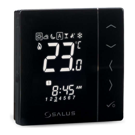
1.3 Product Overview The VS30W/VS30B from SALUS Controls is a stylish and accurate 5/2 or 24h programmable electronic thermostat with a large, easy to read Liquid Crystal Display (LCD). It is flush-mounted temperature controller dedicated for surface heating / cooling, characterized by high thermal inertia. It is connected to the wired wiring centre KL08NSB. -
Page 6: Montage
2. Montage 2.1 Package content 1) VS30W/VS30B thermostat 2) Short instruction 3) Mounting screws 2.2 Proper thermostat location Please note: The ideal position to thermostat mounting is about 1,5m under floor level far from heating or cooling sources. Thermostat can’t be exposed to sunlight or any extreme conditions like for example draft. Because of fire and explosion risk there is not allowed to use thermostat in atmosphere of explosive gases and flammable liquids (eg coal dust). -
Page 7: Connection Description
2.3 Connection description NSB input in Wejście NSB SLAVE thermostat w regulatorze SLAVE T30NC Wyjście NSB NSB output VS30B VS30 VS30W VS30 Legend: Thermal actuator Temperature sensor Symbols explanation: L, N - power supply 230V - NSB - Night temperature reduction (230V output) - SL - 230 V AC output signal S1, S2 - additional temperature sensor... -
Page 8: I A - 4 Wire Installation With Kl08Nsb Wiring Centre
I A - 4 wire installation with KL08NSB wiring centre When VS30W/VS30B thermostat works as a MASTER (group controller) it means it takes control of SLAVE thermostats e.g. VS35W. MASTER thermostat controls SLAVE thermostat only when SLAVE thermostat is in AUTO mode. Comfort (SUN) and economy (MOON) setpoint temperatures are set individually on each thermostat but switching between those temperature is based on time schedule taken from VS30W/VS30B thermostat which works like a group controller. - Page 9 MASTER SLAVE VS30 RT200 RT520 VS30W/VS30B VS35W/VS35B VS35W/VS35B KL08NSB 1 - 8 Strefy 1 - 8 Strefy 1 - 8 Strefy 1-8 Zones 1-8 Zones 1-8 Zones Power Pump Boiler BOILER CONNECTION* max 6 max 6 max 6 T30NC T30NC T30NC per zone per zone...
-
Page 10: I B - 4 Wire Installation With Kl06 Wiring Centre
I B - 4 wire installation with KL06 wiring centre MASTER SLAVE VS30W/VS30B VS35W/VS35B VS35W/VS35B Power Supply 230V AC 4 wires x 0.75 mm2 KL06 PL07 PL06 Actuators wires Pump control wires Boiler control wires 2 x 0.75 mm2 2 x 1 mm2 2 x 1 mm2 T30NC230 THB23030... - Page 11 MASTER SLAVE VS30W/VS30B VS35W/VS35B VS35W/VS35B RT10 // RT20 RT10 // RT20 RT520 RT520 KL06-M KL06-M 1 - 6 Strefy 1 - 6 Strefy 1 - 6 Strefy PL06 1 - 6 Strefy PL06 1-8 Zones 1-8 Zones 1-8 Zones Power Power max 6 max 6...
-
Page 12: Wire Installation With Kl08Nsb Wiring Centre
II - 3 wire installation with KL08NSB wiring centre 3 wire installation with KL08NSB wiring center. Description of the operation rules: - VS30W/VS30B thermostat’s functionality is limited because of 3 wire installation. NSB function is disabled and VS30W/VS30B thermostat doesn’t work as a MASTER thermostat - no effect on other thermostats like VS35W/VS35B. - Page 13 VS30 RT200 RT520 VS30W/VS30B VS30W/VS30B VS30W/VS30B KL08NSB 1 - 8 Strefy 1 - 8 Strefy 1 - 8 Strefy 1-8 Zones 1-8 Zones 1-8 Zones Power Pump Boiler BOILER CONNECTION* max 6 max 6 max 6 T30NC T30NC T30NC per zone per zone per zone AC 230V...
-
Page 14: A - Work With Rm-16A Relay Module - Volt-Free Heating Source Control
III A - work with RM-16A relay module - volt-free heating source control VS30 RT52 VS30W/VS30B N SL (input) (wejście) (wejści RM-16A RM-16 AC 230V AC 230V Connection of a 230 V AC voltage thermostat to a boiler (or other device) with an ON - OFF contact. VS30 091FL III B - work with RM-16A relay module - connection to a solid fuel boiler controller... -
Page 15: C - Work With Rm-16A Relay Module - Connecting An Electrical Device With A Higher Power
III C - work with RM-16A relay module - connecting an electrical device with a higher power than the thermostat relay allows RM-16A RM-16A AC 230V AC 230V PLEASE NOTE! The maximum current consumption of an electrical device should not exceed 16A. VS30 091FL VS30W/VS30B... -
Page 16: Before You Start (First Power Up)
3. Before you start (first power up) 3.1 LCD icon description 2 3 4 5 6 7 8 1. Current active mode 11. Current / set temperature 2. Comfort mode 12. Program number 3. Standard mode 13. AM/PM 4. Economic mode 14. -
Page 17: First Power Up Sequence
3.3 First power up sequence To power on the thermostat you ...display will show all icons..then thermostat will display the have to connect it to the 230V software version. power supply then... Set time format „ ” or „ ” buttons. Set time (hours and minutes) using Confirm by button. -
Page 18: Work Modes
4. Work modes VS30W/VS30B offers a few work modes. Frame on a given icon indicates which mode is currently active. In manual mode only one temperature level is maintained. Thermostat follows programmed schedule when AUTO mode is active („A” icon). Detailed description of work modes is located below: - Frame - means that the work mode is active (the icon of the work mode must be in the center of the frame). -
Page 19: User Settings (Basic Settings)
5. User settings (basic settings) 5.1 Schedule mode - programming schedule To program schedule, please follow steps below: 3 sec. Hold button for 3 seconds to Enter into the schedule settings. enter the menu. There are 4 possible schedule variants. Use and buttons to select schedule variant and confirm by button: Separate schedule for WORKING DAYS. - Page 20 Schedule programming example for the WORKING DAYS variant: buttons to set hour buttons to set mi- Select schedule variant by button. for the first program. nutes for the first program. Confirm Confirm by button. button. Schedule editing will jump to the Confirm by button.
- Page 21 In addition to editing and creating your own schedule, there are also 5 default profiles for built-in schedules. You can select and customize any of the programs listed below. Default programs are selectable through Installer Parameters (parameter D17). Program Profile 1 5 days (Monday to Friday) 2 days (Saturday to Sunday) Program Program...
-
Page 22: Time/Date
5.2 Time/Date To set time/date follow steps below: 3 sec. Go to the time and date settings Hold button for 3 seconds to Choose time and date settings option enter the menu. using button. button. First, select time format (12/24h) Set hour using buttons. -
Page 23: Thermostat Calibration
5.3 Thermostat calibration Thermostat calibration is a function which allows user to recalibrate internal thermostat’s temperature sensor by a given number of degrees (in the range from -3,0 °C to 3,0 °C in 0,5 °C steps). To calibrate thermostat’s temperature sensor please follow steps below: 3 sec. -
Page 24: Heat/Cool Mode Change
5.4 Heat/cool mode change The heating / cooling mode for the thermostat can be changed manually. 3 sec. Go to the thermostat calibration Hold button for 3 seconds to enter the menu. settings using buttons. Confirm by button. -
Page 25: Installer Parameters
6. Installer parameters To enter installer parameters please follow steps below. Please refer to parameters table description before any changes. Use buttons to move up or down between all parameters. Every change/selection confirm by button: Hold buttons for 5 to choose seconds to enter the installer mode. - Page 26 Parameter Default Function Description Values Values SPAN ± 0.5°C (± 1°F) Cooling mode control method SPAN ± 1°C (± 1.5°F) NO - normally open Type of thermoelectric actuator NC - normally closed Valve protection function is intended to protect thermostatic valves against getting stuck or jamming (e.g.
-
Page 27: Factory Reset
7. Factory Reset To RESET VS30W/VS30B thermostat to it’s factory default settings please follow steps below: Hold buttons for 5 buttons Press button to confirm. seconds to enter the installer mode. to choose code „47”. Select „del” and confirm choice by Wait few moments to finish factory ...thermostat will display the pressing... -
Page 28: Error Codes
8. Error codes Error code Description Err02 The maximum / minimum floor temperature has been exceeded Err03 Floor sensor is faulty Err04 Floor sensor is shorted 9. Cleaning and Maintenance The VS30W/VS30B thermostat requires no special maintenance. Periodically, the outer casing can be wiped clean using a dry cloth (please DO NOT use solvents, polishes, detergents or abrasive cleaners, as these can damage the thermostat). -
Page 29: Warranty
11. Warranty SALUS Controls warrants that this product will be free from any defect in materials or workmanship, and shall perform in accordance with its specification, for a period of five years from the date of installation. SALUS Controls sole liability for breach of this warranty will be (at its option) to repair or replace the defective product. - Page 30 United Kingdom www.salus-controls.com SALUS Controls is a member of the Computime Group. Maintaining a policy of continuous product development SALUS Controls plc reserve the right to change specification, design and materials of products listed in this brochure without prior notice.
Need help?
Do you have a question about the Salus Controls VS30W and is the answer not in the manual?
Questions and answers