Table of Contents
Advertisement
Quick Links
STEP 1
Remove top of shipping carton. Verify contents; inspect for
damage.
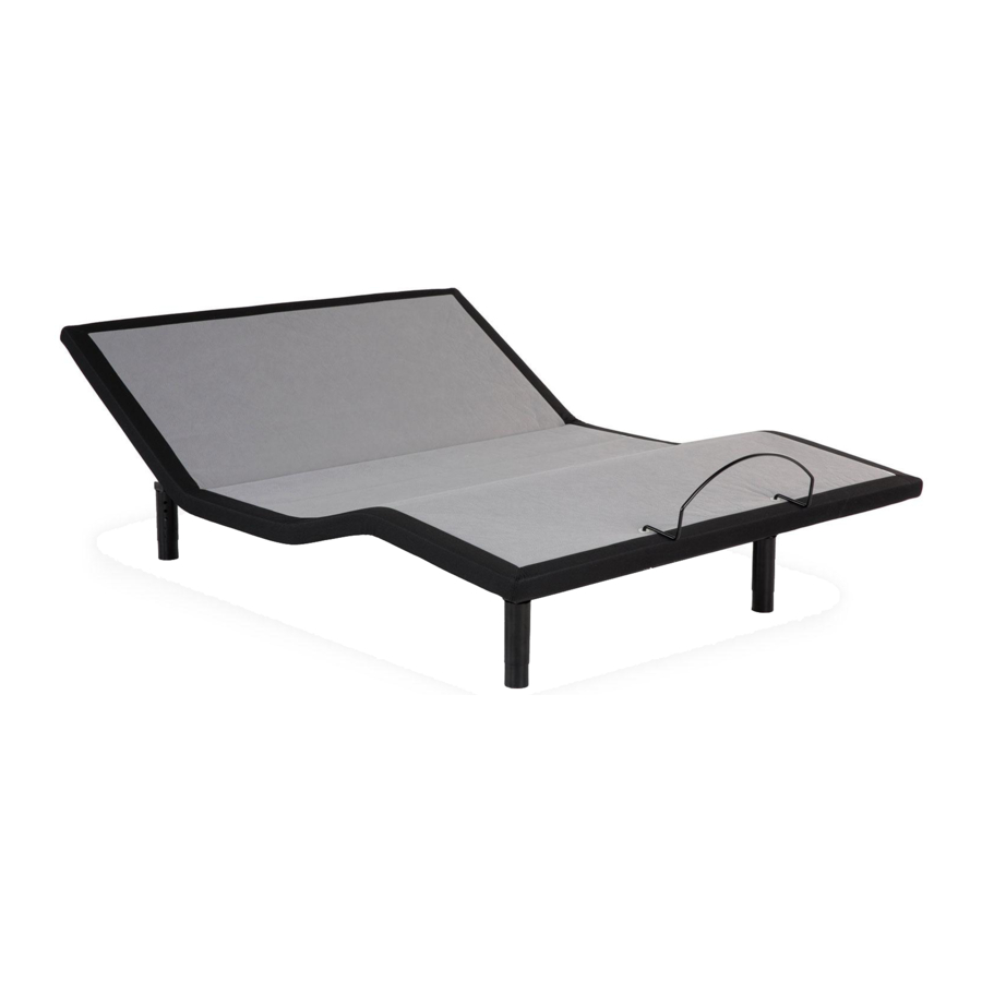
Adjustable Base
setup guide
n 300/600 n K/CK Sectional Base
x6 - Pin-adjustable
Legs
x4 - 3-Inch
Carriage Bolts
and Nuts
x1 - Mattress
Retainer
x3 - AAA
Batteries
291-0070-b EDR15140 5/19
© 2019 Mattress Firm, Inc.
READ ALL INSTRUCTIONS BEFORE USING.
WARNING
!
DUE TO RISK OF INJURY, TWO ADULTS ARE
REQUIRED TO HANDLE AND MOVE ADJUSTABLE
BASE.
SNORE
HEAD
PILLOW
FOOT
ZGRAV
HEAD
FOOT
HEAD
FOOT
MEM
FLAT
ON/OFF
HEAD
FOOT
x1 - Remote
M1
SET
M2
M3
FLAT
M4
Control (varies
according to
base type)
300
600
x2 - T-Spacers
x2 - Center
Support
Brackets
x1 - WRENCH
Advertisement
Table of Contents

Related Manuals for MATTRESS FIRM 300


Summary of Contents for MATTRESS FIRM 300
- Page 1 Adjustable Base setup guide n 300/600 n K/CK Sectional Base READ ALL INSTRUCTIONS BEFORE USING. STEP 1 Remove top of shipping carton. Verify contents; inspect for WARNING damage. DUE TO RISK OF INJURY, TWO ADULTS ARE REQUIRED TO HANDLE AND MOVE ADJUSTABLE BASE.
- Page 2 SETUP STEP 2 CAUTION Cut zip-tie from electrical power supply. Cut (2) zip-ties and remove mattress retainer (set aside) (FIGURE 1). BE CAREFUL USING SHARP INSTRUMENTS. INJURY IS POSSIBLE IF TOOLS ARE NOT USED PROPERLY. FIGURE 1 STEP 3 WARNING Carefully lift base head section out of shipping carton and place on clean surface (FIGURE 2).
- Page 3 SETUP STEP 4 Place a T-Spacer in between the mounting points (each side of base). Line up the holes in the T-Spacers with the holes in the mounting points (FIGURE 3). Place a center support bracket over the mounting points on each side of base. Insert carriage bolts through the square holes in the center support bracket.
- Page 4 STEP 5 WARNING Route FOOT MOTOR CABLE underneath base frame and connect to HEAD MOTOR CABLE (FIGURE 4). POWER CORDS MUST NOT INTERFERE WITH ANY ADJUSTABLE BASE MECHANISMS. 600 MODEL ONLY - Route FOOT MASSAGE MOTOR CABLE underneath base frame and plug into control box (FIGURE 4).
- Page 5 STEP 6 Screw (4) legs into the threaded inserts at the corners of the base frame (FIGURE 5). Screw (2) legs into the threaded inserts of the center support brackets (FIGURE 5). Push pin in to adjust leg height (6 inches to 10 inches). Note: When adjusting legs, make sure base sets level on floor.
- Page 6 SETUP STEP 8 Install (3) batteries in remote control. SNORE HEAD PILLOW FOOT Plug power cord into power outlet. Note: An electrical ZGRAV HEAD FOOT surge protection device is recommended (not included). HEAD FOOT Operate remote control to test base functions (FIGURE 6) FLAT ON/OFF HEAD...
- Page 7 Note: If adjustable base will not operate, refer to the Troubleshooting section of the owner’s manual. To download a copy of the owner’s manual, visit https://lpadjustablebeds.com/om/mattressfirm or call Mattress Firm at 844-628-8376. To register your adjustable base, please go to https://lpadjustablebeds.com/register...
Need help?
Do you have a question about the 300 and is the answer not in the manual?
Questions and answers
I have tried everything that the manual of troubleshooting says and I cannot get my bed to go flat (head of the bed). All the plugs are in tight, placed new batteries in the remote nothing seems to happen. I purchased my bed in April 2022. My order #SO340407039. This is the first time I have ever had any problems with my bed. What is happening?
Purchased mine in September 2024 and tonight out of the blue head won’t go down. Plugs are all in and nothing has been changed. Foot raises and lowers just fine.
Possible causes for the head of your Mattress Firm 300 adjustable base not going flat could include:
1. Motor Issue: The buzzing sound suggests the motor for the head section may be trying to work but is mechanically stuck or failing.
2. Control Box Problem: If the remote and power supply seem fine, the issue could be with the control box that manages motor functions.
3. Mechanical Obstruction: There might be something physically blocking the head section from moving.
4. Synchronization or Programming Fault: If the remote and base are not properly synced, certain functions might not respond correctly.
Check the power supply (ensure the DC light is on), confirm the remote is working with new batteries, and try reprogramming the remote. If these steps do not fix the issue, the problem likely lies with the control box or motor.
This answer is automatically generated
Power cord is missing after move. How do I get a new one?
You can purchase a power cord compatible with the Mattress Firm 300 adjustable base from a store that sells adjustable base parts. The product listing mentions a power cord compatible with the Mattress Firm 300/600 series, priced at $99.00. Before ordering, you need to confirm that it is the correct cord set needed. There are 22 units in stock.
This answer is automatically generated
I purchased one from Avon 5 years ago the motor just stopped? Any ideas
Possible causes for the motor stopping on a Mattress Firm 300 adjustable bed include:
1. Electrical Issues – Check if the power cord is properly plugged in and if the electrical outlet is working by testing it with another device. Also, verify if the circuit breaker has tripped.
2. Defective Surge Protector or Outlet – A faulty surge protector or electrical outlet could prevent power from reaching the motor.
3. Thermal Switch Activation – If the base was operated beyond its rated duty cycle, the thermal switch may have opened. Wait 30 minutes before trying again.
4. Obstructions – The base mechanism may be blocked by an object. Check and remove any obstructions.
5. Proximity to a Wall – The head section may be too close to a wall, preventing movement.
6. Buzzing Sound – If the motor buzzes but does not lift, it may indicate a mechanical issue or motor failure.
If the issue persists after troubleshooting, the motor may need repair or replacement.
This answer is automatically generated
The motion sensor feature of the underbed lighting is no longer working correctly. It's either on or off. I'd love to turn that feature back on
The provided context does not contain specific instructions for fixing the motion sensor feature of the Mattress Firm 300 underbed lighting. However, you can try the following general troubleshooting steps:
1. Power Cycle: Unplug the adjustable base from the power outlet, wait a few minutes, and plug it back in.
2. Remote Resync: Follow the desyncing and reprogramming process for the remote control.
3. Check for Obstructions: Ensure no objects are blocking the motion sensor.
4. Inspect Wiring: Verify that all cables and connections are secure.
5. Contact Support: If the issue persists, refer to the product manual or contact the manufacturer for further assistance.
This answer is automatically generated
How to set memory on controller
To set a memory position on the controller for the Mattress Firm 300 adjustable base:
1. Adjust the base, massage, and underbed light to the desired position.
2. Press and hold the "Set" button until the massage motors chirp once.
3. Press the desired memory button (M1, M2, M3, or M4) until the massage motors chirp three times.
This saves the current position to the selected memory button.
This answer is automatically generated