
Related Manuals for Dreadbox Nyx V2


Summary of Contents for Dreadbox Nyx V2
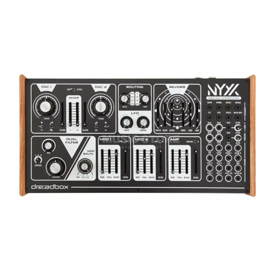
- Page 1 Owner’s Manual ANALOG SYNTHESIZER 2 Oscillators 12-24dB Dual Filter 2 Function Generators Extensive Digital Reverb 30 eurorack patch points in Athens, GR...
-
Page 2: Table Of Contents
Contents Introduction ..............3 The Oscillators ..............4 The Filter ................. 5 The Modulators .............. 5 The Routing ..............6 The LFO ................9 The Reverb ............... 9 The Amp / Drone Mode ..........9 Patch Bay ..............10 MIDI Interface and DIP Switch ........11 The Service Mode ............ -
Page 3: Introduction
Nyx V2.0 / Release Date: 07.05.2019 After the warm embrace of the Nyx V1 synthesizer, it was time to follow the idea hiding behind the Erebus V3. The new version of Nyx synthesiz- er has adapted to the format of the Erebus V3 and more features have been added to its arsenal, including: •... -
Page 4: The Oscillators
OSC 2 offers a triangle wave instead of a pulse wave. We suggest you to use the Nyx v2 with a MIDI interface, as its paraphony and oscillators’ tuning preci- sion heavily relies on MIDI. -
Page 5: The Filter
1 : Only MOD1 controls the Filter About the Dual Filter The Nyx V2 Synthesizer, is equipped with 2 pre-fed Filters, each at 12dB/oct. You can achieve various Filter combinations, from a Classic 24dB/oct Low Pass or even a variable width Band Pass. -
Page 6: The Routing
The Routing The routing section is the most important part of the Nyx v2 synthesizer. Understanding how it works, is the key to create complex sounds. There are 2 routing controls (+ the MOD Routing, which is ex- plained on the Filter section), VCO and VCF. - Page 7 HALF: Both VCOs are being sent to VCF2. VCO1 VCF1 VCO2 VCF2 VCF ROUTE LP: Stands for LOW PASS. Both filters are set to a Low Pass mode and in series. VCF1 VCF2 BP: Stands for BAND PASS. The filters are in series, but VCF1 is on HP mode and VCF2 is on LP mode. VCF1 VCF2 HP: Stands for HIGH PASS.
- Page 8 Now combining all the Routing information, we have created a table with the following options. 12dB/oct 24dB/oct 12dB/oct 24dB/oct Low Pass Low Pass Band Pass High Pass VCF2 is free VCO1 VCO1 VCO1 VCO1 24dB/oct 12dB/oct 24dB/oct 12dB/oct Low Pass Band Pass High Pass Low Pass...
-
Page 9: The Lfo
2. DEPTH knob - sets the LFO amount The Reverb We have developed a new algorithm for the Reverb of the Nyx V2, to accompany drones so as to create haunted and aetherial soundscapes. The first three slider controls consist the modulation of the effect and the last three are the actual reverb controls. -
Page 10: Patch Bay
The Patch Bay The Nyx V2 has 30 patch points, offering endless routing and modulation possibilities. The Patch Bay is consisted of 4 major parts: GENERAL OUTPUTS 1. GATE : outputs the gate CV (0-6.5V pulse) 2. WHEEL : outputs the modulation wheel CV (0-5V) 3. -
Page 11: Midi Interface And Dip Switch
If that is the case, avoid using the MIDI THRU. Also, the MIDI THRU can be used to send a second MIDI device to control the Nyx V2 at the same time. Here is the complete list that the MIDI interface will handle:... -
Page 12: The Service Mode
Service Mode / Fine Tuning Procedure In order to tune the Nyx V2 synthesizer, a MIDI keyboard, a pair of speakers and a tuner is needed. Con- nect everything and turn the unit on for at least 30 minutes on Autotune Mode (DIP1 ON). -
Page 13: Limited Warranty
Firmware Update In order to upgrade the Firmware of the Nyx V2 Synthesizer, you will need to follow the instructions of the .zip file, which you can download from www.dreadbox-fx.com/nyx2 Then connect a MIDI cable from your MIDI device to the unit’s MIDI IN port, Turn the DIP switch 6 to the ON position and power on your unit.
Need help?
Do you have a question about the Nyx V2 and is the answer not in the manual?
Questions and answers