Table of Contents
Advertisement
Quick Links
BEFORE YOU GET STARTED
Before you start the construction of this DIY project, make sure that
you have basic soldering skills and that you can identify electronic
components. If it is your first time in soldering, there are several tuto-
rials on youtube, that will help you :)
It would be easier and helpful for you to work on a big desk, so as
to have plenty of space to work on. Also a room with an open win-
dow would be perfect when you solder.
Before you start the soldering process, make sure you have all the
components needed and noted in the BILL OF MATERIALS SECTION.
Please note that we might have included more components than
needed or (hopefully not) less. It would be very helpful if you count
all components before starting the project, but without removing
these from their bags .
Advertisement
Table of Contents

Related Manuals for Dreadbox ANTIPHON


Summary of Contents for Dreadbox ANTIPHON
- Page 1 BEFORE YOU GET STARTED Before you start the construction of this DIY project, make sure that you have basic soldering skills and that you can identify electronic components. If it is your first time in soldering, there are several tuto- rials on youtube, that will help you :) It would be easier and helpful for you to work on a big desk, so as to have plenty of space to work on.
-
Page 2: Table Of Contents
CONTENTS BILL OF MATERIALS..............3 TOOLS YOU WILL NEED............4 STEP 1 - RESISTORS...............5 STEP 2 - ICs & SOCKETS............8 STEP 3 - CAPACITORS............9 STEP 4 - TRIMMERS & TEMPCO.........11 STEP 5 - JACKS & POTENTIOMETERS........13 STEP 6 - HEADERS & SPACERS..........14 STEP 7 - TEST, ICS, TUNE &... -
Page 3: Bill Of Materials
BILL OF MATERIALS Resistors Other 45 33k 41 100k 1 10pin male ribbon connector 22 470R 3 10 pin male header 20 18k 3 10 pin female header 11 3k3 2 reverb connectors 8 TEMPCO 2k 16 5k trimmer Plastic POT 14 Slider 10KB Capacitors 22 3,5mm jack... -
Page 4: Tools You Will Need
TOOLS YOU WILL NEED Small Screwdriver Wire Cutter Solder Soldering Iron Tuner Patch Cables Multimeter 2,5mm hex screw driver... -
Page 5: Step 1 - Resistors
STEP 1 - RESISTORS Locate and solder all 45pcs of 33K resistors. Locate and solder all 22pcs of 470R resistors. When you are done, cut carefully all the excess leads. When you are done, cut carefully all the excess leads. Locate and solder all 41pcs of 100K resistors. - Page 6 Locate and solder all 11pcs of 3k3 resistors. There are 3 different kinds of Diodes in the Kit. Here we are looking at two of them, 1n4148 and zener 3v6. As they both look almost When you are done, cut carefully all the excess leads. identical, in order to distinguish them, Zener 3v6 diodes not only have a “3v6”...
- Page 7 Now, we will install 2 components: 2 pcs10R and 17pcs zener 3v6. Locate and solder all 19pcs of 1N4148 diodes. When you are done, cut carefully all the excess leads. When you are done, cut carefully all the excess leads. WATCH OUT FOR DIODES ORIENTATION!!! THE BLACK LINE ON DIODES , SHOULD MATCH THE DEPICTION ON THE PCB...
-
Page 8: Step 2 - Ics & Sockets
STEP 2 - ICS & SOCKETS Locate and solder 11pcs of TL074. Some ICs have a dot, while oth- Locate 5pcs of 16pin IC socket and 1pcs of 8pin IC socket. ers have a semicircle cut. On the pcbs the orientation is indicated as a semi- circle. -
Page 9: Step 3 - Capacitors
STEP 3 - CAPACITORS Locate (in their dedicated bag) and solder all 61pcs of 470 pF capacitors. When you are done, cut carefully all the excess leads. - Page 10 Locate and solder: - 29pcs 100nF (marked 104) ceramic capacitors. All of the unlabeled capacitors on the PCB are 100nF - 17pcs 10uF electro capacitors (blue ones, polarized) - 1pcs of 220uF electro capacitor (black one, polarized) Polarized capacitors: The longer lead goes to + BE CAREFULL to solder the electrolytic capac- itors as tight as possible, otherwise they might not fit between the pcbs!
-
Page 11: Step 4 - Trimmers & Tempco
STEP 4 - TRIMMERS AND TEMPCO Locate and solder all 16pcs of 4k7 trimmer potentiometers, as shown on the picture. Also, locate and solder 2pcs of 1n4004 (or 1n400x) diodes. - Page 12 From the Resistor bag, you will have 8 small resistors left. These are the Tempco, and they are very important for the oscillator’s stability. Locate them and bend them. Then place them as shown and carefully solder them from the top...
-
Page 13: Step 5 - Jacks & Potentiometers
STEP 5 - JACKS & POTENTIOMETERS By now, you should have soldered everything except for the jacks, Locate and solder the slider potentiometers. BE CAREFULL no to use potentiometers and the ribbon sockets. Take a look at your pcbs more that 280 C degrees, and no more than 4 sec/ pad. -
Page 14: Step 6 - Headers & Spacers
STEP 6 - HEADERS AND SPACERS 1. Locate and solder 3x female 10pin headers as 3. The pics below show their exact location and orientation. shown in the picture 2. Locate 4 sets of these screw/spacer... - Page 15 4. Mount the male headers on the female ones, as shown on the picture. And you will solder these later.
- Page 16 5. Solder the one 10 pin ribbon header and 6. Locate 6 of these Here is how your top board should look like. the reverb headers as shown on the picture screw+spacer+nut sets below. correct wrong...
- Page 17 7. Make a quick check that your panel fits and everything is placed correctly. 8. Temporarily place and screw the bottom This is how the header should look like from the side. board with the top one. Now solder the headers.
-
Page 18: Step 7 - Test, Ics, Tune & Finalize
What you need to do, is to power up the module and measure that it gets the correct power supply, before you install these last senstive ICs. So, connect the antiphon (without the front panel) to a eurorack compatible power supply connected with the ribbon cable provided. - Page 19 Now, remove the screws that hold the bottom board and unplug the two boards.
- Page 20 It is time to install 5pcs of V2164 and 1pc of LM386. BE CAREFUL on the orientation! If the ICs Set the tempco resistor back into are placed in the wrong way they will be burned! place as shown in the picture. Place the bottom board back.
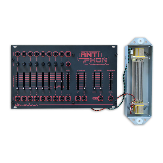
- Page 21 Finally place the spring reverb as shown. You can have the tank free, out of the euro- rack case, or you can screw / stick it into it. Finalizing the Kit. Now, you need to check that everything works, and then tune it. To do that please check on our online YouTube Channel : http://www.youtube.com/c/Dreadbox-synths...
Need help?
Do you have a question about the ANTIPHON and is the answer not in the manual?
Questions and answers