Advertisement
Quick Links
US Patents: 6,511,483
6,805,696
European Patent: EP 0 890 313 B1
EQUIPMENT
SELECTION
. . . . . . . . . . . . .
Model SHC 140
. . . . . . . . . . . . . . . . . . . . . . . . . . . . .
Model SHC 140 Ergonomic
Model SHC 140 Left Handed
Model SHC 165 Standard
. . . . . . . . . . . . . . . . . . . .
Model SHC 165 Ergonomic
Model SHC 165 Left Handed
Model SHC 165B Brisket
. . . . . . . . . . . . . . . . . . . . .
Model SHC 165G (16mm)
. . . . . . . . . . . . . . . . . . . .
Model SHC 165G (13mm)
. . . . . . . . . . . . . . . . . . . .
Model SHC 165GT (7 Blades)
Model SHC 205
. . . . . . . . . . . . . . . . . . . . . . . . . . . .
Model SHC 205, Left Handed
Hydr. Power Unit, Single Trigger, 575V/60Hz
Hydr. Power Unit, Single Trigger, 460V/60Hz
Hydr. Power Unit, Single Trigger, 440--220V/50Hz 4027274
Hydr. Power Unit, Dual Trigger, 460V/60Hz
Hydr. Power Unit, Dual Trigger, 440--220V/50Hz
Balancer SHC 140, 165, 165B and 205
Balancer SHC 165G and 165GT
Tool Kit
. . . . . . . . . . . . . . . . . . . . . . . . . . . . . . . . . . . .
JARVIS
6207016::::.b
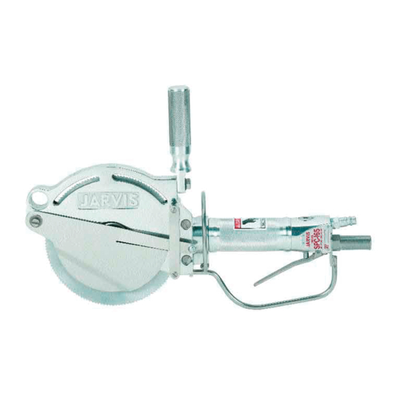
Model SHC 140, 165, 165B, 165G,
165GT & 205 Hydraulic Circular Saw
SHC 165
Left
Right
SHC 165B
Ordering No.
4007028
. . . . . . . . . . . . . . . . . . .
4007052
. . . . . . . . . . . . . . . . . .
4007037
4007029
. . . . . . . . . . . . . . . . . . .
4007053
. . . . . . . . . . . . . . . . . .
4007032
4007036
4007089
4007077
. . . . . . . . . . . . . . . . .
4007087
4007075
. . . . . . . . . . . . . . . . .
4007076
. . . .
4027283
. . . .
4027271
. . . . .
4027273
.
4027264
. . . . . . . . .
4042033
. . . . . . . . . . . . . . .
4042044
8039163
TABLE OF
CONTENTS
. . . . . . . . . . . . . . . . . . . . . . . . . . . .
Safety Messages to Employer and Safety
D
Director
. . . . . . . . . . . . . . . . . . . . . . . . . . . . . . . . .
Safety Messages to Operators, Maintenance
D
and Cleanup Personnel
Parts Diagram and List
D
Installation Diagram
D
Specifications
D
Installation Instructions
D
Operation Instructions
D
Maintenance Instructions
D
PRODUCTS CORPORATION
33 ANDERSON ROAD, MIDDLETOWN, CONNECTICUT 06457-4926
UNITED STATES OF AMERICA E--MAIL.
TEL. 860-347-7271
SHC 165
ERGONOMIC
SHC 165G
SHC 165GT
. . . . . . . . . . . . . . . . . . .
. . . . . . . . . . . . . . . . . . . .
. . . . . . . . . . . . . . . . . . . . .
. . . . . . . . . . . . . . . . . . . . . . . . . . .
. . . . . . . . . . . . . . . . . . .
. . . . . . . . . . . . . . . . . . . .
. . . . . . . . . . . . . . . . .
sales@jarvisproducts.com
jarvisproducts.com
FAX. 860-347-6978
WWW.
Page
2
3
4
12
14
14
15
16
Advertisement

Subscribe to Our Youtube Channel
Related Manuals for Jarvis SHC 140


Summary of Contents for Jarvis SHC 140
- Page 1 4027264 Operation Instructions ....Balancer SHC 140, 165, 165B and 205 ..4042033 Balancer SHC 165G and 165GT .
- Page 2 9. Avoid injury. Do not permit the tool to be misused. 10. If you resell or distribute a Jarvis product, you must provide the purchaser with the appropriate safety sheets and tool brochure. Additional copies of safety sheets and tool brochures will be provided upon request.
- Page 3 3 of 20 Model SHC 140, 165, 165B, 165G, 165GT and 205 Keep hands clear. SAFETY MESSAGES TO OPERATORS, MAINTENANCE AND CLEANUP PERSONNEL REMOVE ANY MALFUNCTIONING TOOL FROM SERVICE REPORT ANY PROBLEMS TO YOUR SUPERVISOR 1.
- Page 4 Model SHC 140, 165, 165B, 165G, 165GT and 205 page 4 of 20 Figure A SHC- -140, 165 and 165B * optional -- must remove helical insert in blade guard to install “T” handle. ** special tool 8039152 is available...
- Page 5 5 of 20 Model SHC 140, 165, 165B, 165G, 165GT and 205 Figure B SHC 205 a= 20 lbf--ft (27 Nm) ITEM PART NO. PART NAME 3025017 Depth Gage Assy, RH 3025021 Depth Gage Assy, LH...
- Page 6 Model SHC 140, 165, 165B, 165G, 165GT and 205 page 6 of 20 Figure D SHC- -165G * Spanner wrench 8039093 is supplied a= 20 lbf--ft (27 N--m) b= 35 lbf--ft (47 N--m) ITEM PART NO.
- Page 7 7 of 20 Model SHC 140, 165, 165B, 165G, 165GT and 205 Figure F SHC- -165G SHC- -165GT ITEM PART NO. PART NAME ITEM PART NO. PART NAME 1055753 Hex Head Screw 1004230 Split Lock Washer...
- Page 8 Model SHC 140, 165, 165B, 165G, 165GT and 205 page 8 of 20 Figure G Hydraulic Motor Assembly 3008172 Right Hand 3008189 Left Hand New Style Old Style used after used before Sept 2004 Oct 2004 c= 50 lbf--in (5.6 N--m)
- Page 9 9 of 20 Model SHC 140, 165, 165B, 165G, 165GT and 205 Figure H Hydraulic Power Unit with “A” Flanged Pump 4027271 ITEM PART NO. PART NAME ITEM PART NO. PART NAME Control Box Assembly 1022043 Dir.
- Page 10 Model SHC 140, 165, 165B, 165G, 165GT and 205 page 10 of 20 Figure I 4027115 Hydraulic Power Unit with “AA” Flanged Pump ITEM PART NO. PART NAME 1063844 din/iso Coil for Valve, 230V 1072135 din/iso Connector, 115V...
- Page 11 11 of 20 Model SHC 140, 165, 165B, 165G, 165GT and 205 Figure J Control Box Assembly Single Trigger Tools Dual Trigger Tools ITEM PART NO. PART NAME ITEM PART NO. PART NAME 1032266 Mounting Plate...
- Page 12 Model SHC 140, 165, 165B, 165G, 165GT and 205 page 12 of 20 Figure 1 Hose Connection Diagram Single Trigger Control Box Assembly (Factory Installed on Hydraulic Power Unit) Hydraulic Power Unit Control Box Assembly Supply Pressure Inlet...
- Page 13 13 of 20 Model SHC 140, 165, 165B, 165G, 165GT and 205 Figure 2 Hose Connection Diagram Dual Triggers Control Box Assembly (Factory Installed on Hydraulic Power Unit) Hydraulic Power Unit Return Control Box Pressure Line Assembly...
- Page 14 Model SHC 140, 165, 165B, 165G, 165GT and 205 page 14 of 20 SPECIFICATIONS INSTALLATION INSTRUCTIONS All Models ALWAYS DISCONNECT THE POWER SUPPLY IN Motor Power 2.5 hp 1865 W ACCORDANCE WITH OSHA’S LOCKOUT/TAGOUT PROCEDURES (29 CFR 1910.147) BEFORE PERFORM- Blade Speed at 3.5 gal/min...
- Page 15 15 of 20 Model SHC 140, 165, 165B, 165G, 165GT and 205 Dual Trigger Tools: Refer to Figure J, page 11. ACCORDANCE WITH OSHA’S LOCKOUT/TAGOUT PROCEDURES (29 CFR 1910.147) BEFORE PERFORM- 6.3 For the air supply line: use “Y” fitting (item 124, ING ANY REPAIRS OR MAINTENANCE.
- Page 16 Model SHC 140, 165, 165B, 165G, 165GT and 205 page 16 of 20 3.3 When the desired length of cut is reached, re- tool should not start. Repeat this procedure lease the trigger. This will stop the blade from holding the other trigger.
- Page 17 17 of 20 Model SHC 140, 165, 165B, 165G, 165GT and 205 3.6 Remove blade insert holder (item 83) with blade 5 BLADE SCRAPER REMOVAL: (SHC- -165G and inserts (item 101) and slinger (item 84) still at- SHC- -165GT) tached.
- Page 18 Model SHC 140, 165, 165B, 165G, 165GT and 205 page 18 of 20 7.9 Disassemble the pinion gear. 8.1.2 When installing internal retaining ring (item 27), make sure that the beveled edge faces 7.9.1 Press the ball bearing (item 26) from the away from gear housing (item 21, 50 or 99).
- Page 19 19 of 20 Model SHC 140, 165, 165B, 165G, 165GT and 205 10.7 Replace the o- -rings (items 142 and 145) with 11.14 Reassemble the motor to the gear housing, re- new ones from seal kit and apply a liberal coat...
- Page 20 Model SHC 140, 165, 165B, 165G, 165GT and 205 page 20 of 20 12.13.2 The needle bearing for drive shaft (item 148 New Style Motor or 175) can be pressed out through the gear 12.11 Disassemble motor as described in section 11, head side of the front motor housing (item steps 11.2 - - 11.7.
Need help?
Do you have a question about the SHC 140 and is the answer not in the manual?
Questions and answers
Mijn zaag verliest vermogen , wat te doen
If your Jarvis SHC 140 saw is losing power, follow these steps:
1. Check Hydraulic Fluid Level – Ensure the hydraulic fluid in the power unit is at the correct level.
2. Inspect Grease Maintenance – Apply Jarvis 1315 White Grease to the grease fitting four times per day.
3. Verify Power Supply – Ensure all hydraulic and air hoses are properly connected and the power supply is functioning.
4. Examine Blade Condition – Avoid banging the blade into bone, as damage could reduce cutting efficiency.
5. Report Issues – If the problem persists, remove the tool from service and notify your supervisor immediately.
Always disconnect all hydraulic and power supplies before performing maintenance.
This answer is automatically generated