Table of Contents
Advertisement
Advertisement
Table of Contents

Related Manuals for CHCNAV Huayi E91


Summary of Contents for CHCNAV Huayi E91
- Page 1 ® HUAYI NAV E91 Geodetic GNSS Receiver User Guide Revision 1.0 November 30, 2018...
-
Page 2: Table Of Contents
Table of Content Table of Content Table of Content....................2 Preface ......................... 5 Copyright ........................ 5 Safety Warnings ..................... 5 FCC Interference Statement ................... 5 CE Interference Statement ..................6 Introduction ....................7 1.1 Safety Information ..................7 1.1.1 Warnings and Cautions ..............7 1.1.2 Regulations and Safety ............... - Page 3 Table of Content 5.1 Status menu ....................29 5.1.1 Position submenu ................29 5.1.2 Activity submenu ................30 5.1.3 Google Map submenu ..............31 5.2 Satellites menu ..................... 31 5.2.1 Tracking Table submenu ..............31 5.2.2 Tracking Info. Table submenu ............32 5.2.3 Tracking Skyplot submenu ...............
- Page 4 5.8.3 Config File ..................51 5.8.4 System Log Download submenu ............51 5.8.5 User Log ................... 52 5.8.6 Firmware Update submenu ............. 52 5.8.7 GNSS Board Upgrade ............... 52 5.8.8 Radio Upgrade.................. 53 5.8.9 Upgrade Online ................53 5.8.10 GNSS Registration submenu ............53 5.9 Cloud Service Setting menu .................
-
Page 5: Preface
Preface Preface Copyright Copyright 2016-2017 HUAYI NAV | Shanghai Huayi Navigation Technology Ltd. All rights reserved. The HUAYI NAV are trademark of Shanghai Huayi Navigation Technology Limited. All other trademarks are the property of their respective owners. Trademarks All product and brand names mentioned in this publication are trademarks of their respective holders. -
Page 6: Ce Interference Statement
Preface CE Interference Statement Declaration of Conformity: Hereby, Shanghai Huayi Navigation Technology Ltd. declares that this E91 is in compliance with the essential requirements and other relevant provisions of Directive 2014/53/EU. A copy of the Declaration of conformity can be found at Shanghai Huayi Navigation Technology Ltd. -
Page 7: Introduction
Introduction 1 Introduction The E91 GNSS Receiver User Guide describes how to set up and use the HUAYI NAV® E91 GNSS receiver. In this manual, “the receiver” refers to the E91 GNSS receiver unless otherwise stated. Even if you have used other Global Navigation Satellite Systems (GNSS) products before, HUAYI NAV recommends that you spend some time reading this manual to learn about the special features of this product. -
Page 8: Use And Care
Introduction 1.1.3 Use and Care This receiver is designed to withstand the rough environment that typically occurs in the field. However, the receiver is high-precision electronic equipment and should be treated with reasonable care. CAUTION - Operating or storing the receiver outside the specified temperature range will cause irreversible damage. -
Page 9: Getting Started With E91
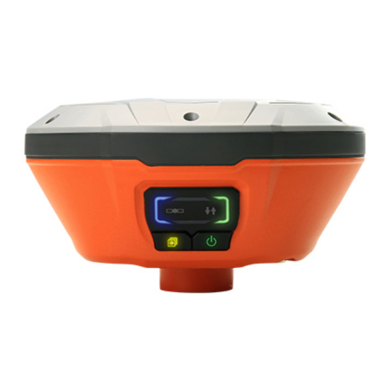
Getting Started with E91 2 Getting Started with E91 2.1 About the Receiver The E91 GNSS receiver incorporates a GNSS engine, GNSS antenna, internal radio (410 MHz – 470 MHz), 4G cellular modem, Bluetooth and Wi-Fi in a ruggedized and miniature unit that is easy for you to set up an all-in-one RTK rover or mobile base station. - Page 10 Getting Started with E91 Name Description • When the receiver is searching satellites, the green LED flashes once every 5 seconds Satellites LED (blue) • When the receiver has tracked N satellites, the green LED will flash N times every 5 seconds. •...
- Page 11 Getting Started with E91 the power LED (orange) will flash once per 2 s. • If the power of internal battery is between 70% and 99%, the power LED (orange) will flash once per 4 s. • If charging is finished, the power LED (orange) will keep awake.
-
Page 12: Receiver Back And Bottom
Getting Started with E91 2.2.2 Receiver Back and Bottom The following figures show the back and bottom view of the receiver. SIM card slot Name Description One micro SIM card slot (12 mm × 15 mm) provides 4G SIM card slot network solution. -
Page 13: Battery And Power
Getting Started with E91 • Use the GPS to PC data cable to realize RS-232 communications between the receiver and computer or controller. • Use the GPS to PC data cable to transmit differential data to an external radio. Reserved port Reserved port •... -
Page 14: External Power Supply
Getting Started with E91 2.3.2 External Power Supply There is one recommended method for providing the external power (9 V DC to 36 V DC): Connect the receiver to a vehicle battery by using the external power cable. WARNING - Use caution when connecting external power cable's clip leads to a vehicle battery. -
Page 15: Product Basic Supply Accessories
Getting Started with E91 2.5 Product Basic Supply Accessories 2.5.1 Base Kit Basic Supply Item Picture E91 Geodetic GNSS Receiver UHF Bar Antenna (410-470 MHz) USB Cable GPS to PC Data Cable Charging Cable H.I. Tape Extension pole... -
Page 16: Rover Kit Basic Supply
Getting Started with E91 Tribrach with optical plummet Auxiliary H.I. Tool Tribrach adaptor Transport Hard Case 2.5.2 Rover Kit Basic Supply Item Picture E91 Geodetic GNSS Receiver UHF Bar Antenna (410-470 MHz) USB Cable GPS to PC Data Cable... -
Page 17: Downloading Logged Data
Getting Started with E91 Charging Cable 2M Range Pole w/bag Auxiliary H.I. Tool Transport Hard Case 2.6 Downloading Logged Data Data logging involves the collection of GNSS measurement data over a period at a static point or points, and subsequent post-processing of the information to accurately compute baseline information. - Page 18 Getting Started with E91 Double click the folder “repo_receiver SN” (take 3203970 as example), you will see 9 folders. The “push_log” folder is used to save the log files, and the other 8 folders represent different logging sessions and are used for store static data. Double click the folder that you have configured to store the static data, you will see the folder(s) created by the E91 system automatically and named by the date which is decide by GPS time when you start to log data.
-
Page 19: Web Server Download
Getting Started with E91 Notes: For hcn files, the name of the file is represented as XXXXXXDDDNN, where XXXXXX is the SN of the receiver, DDD is day of year, and NN is the recording session. WARNING – The static data will be saved in the first logging session, the “record_1”... - Page 20 Getting Started with E91 Double click the folder that you have configured to store the static data, you will see the folder(s) created by the E91 system automatically and named by the date which is decide by GPS time when you start to log data. Select the destination folder and double click it, and then you can see several folders named with the date.
-
Page 21: Equipment Setup And Operation
Equipment Setup and Operation 3 Equipment Setup and Operation 3.1 Post-processing Base Station Setup For good performance, the following base station setup guidelines are recommended: Components: Name E91 GNSS receiver Extension pole (30 cm) Tribrach adaptor... -
Page 22: Real-Time Base Station Setup
Equipment Setup and Operation Tribrach w/ Opti Aluminum tripod Steps: (1) Put tripod in the target position, center and level it roughly. (2) Place and lock the tribrach in the tripod. (3) Screw the receiver onto the tribrach. (4) Center and level the receiver more precisely. (5) Connect the receiver to external battery by using external power cable if necessary. - Page 23 Equipment Setup and Operation Name E91 GNSS receiver UHF whip antenna Extension pole (30 cm) Tribrach adaptor Tribrach w/ Opti Aluminum tripod Micro SIM card (12 mm × 15 mm)
-
Page 24: External Uhf
Equipment Setup and Operation Steps: (1) Put tripod in the target position, center and level it roughly. (2) Place and lock the tribrach in the tripod. (3) If work as a cellular base station, the SIM card need to be inserted. (4) Screw the receiver onto the tribrach. - Page 25 Equipment Setup and Operation Name E91 Geodetic GNSS receiver Extension pole (30 cm) Tribrach adaptor Tribrach w/ Opti GPS to datalink cable (power cable) Aluminum tripod Datalink antenna mounting pole kit 3 m cable for datalink antenna Pole mounting External UHF datalink Steps: (1) Put tripod in the target position, center and level it roughly.
-
Page 26: Real-Time Rover Station Setup
Equipment Setup and Operation 3.3 Real-Time Rover Station Setup For good performance, the following rover station setup guidelines are recommended: Components: Name E91 Geodetic GNSS receiver UHF whip antenna 2M range pole w/ bag Steps: (1) If work as a cellular rover station, the SIM card need to be inserted. (2) Screw the receiver onto the pole. -
Page 27: Connecting To An Office Computer
Connecting to an Office Computer the receiver. (4) Turn on the receiver by pressing the power button for 3 s. (5) Switch on the data controller and connect it to the receiver. (6) Use software to configure the receiver as cellular rover or UHF rover mode. (7) Center and level the receiver more precisely. -
Page 28: Configuring Through A Web Browser
Configuring through a web browser 5 Configuring through a web browser Supported browsers: • Google Chrome • Microsoft Internet Explorer ○ version 10, or higher To connect to the receiver through a web browser: 1. Turn on the Wi-Fi of the receiver. 2. -
Page 29: Status Menu
Configuring through a web browser This web page shows the configuration menus on the left of the browser window, and the setting on the right. Each configuration menu contains the related submenus to configure the receiver and monitor receiver performance. This chapter describes each configuration menu. -
Page 30: Activity Submenu
Configuring through a web browser receiver clock information. 5.1.2 Activity submenu Lists several important items to help you understand how the receiver is being used and its current operating condition. Items include the identities of currently tracked satellites, internal and external storage usage rate, how long the receiver has been operational, state of the internal battery, power source state, files being logged, and data streams being output. -
Page 31: Google Map Submenu
Configuring through a web browser 5.1.3 Google Map submenu Tap this submenu to show the location of the receiver on Google map. 5.2 Satellites menu Use the Satellites menu to view satellite tracking details and enable/disable GPS, SBAS, GLONASS, BDS and Galileo constellations. These menus include tabular and graphical displays to provide all required information on satellite tracking status. -
Page 32: Tracking Info. Table Submenu
Configuring through a web browser 5.2.2 Tracking Info. Table submenu The following figure is an example of satellite track diagram page. Users can determine the satellite types and the corresponding SNR of L-band carriers to be displayed in any combination. 5.2.3 Tracking Skyplot submenu The following figure is an example of Skyplot page. -
Page 33: Satellite Activation Submenu
Configuring through a web browser 5.2.4 Satellite Activation submenu Use this menu to enable or disable satellites. 5.3 Receiver Configuration menu Use this menu to configure settings such as the antenna type and height, elevation mask and PDOP setting, the reference station coordinates, receiver resetting and web interface language: 5.3.1 Description This submenu shows the receiver information and reference station information,... -
Page 34: Antenna Configuration Submenu
Configuring through a web browser 5.3.2 Antenna Configuration submenu Use this screen to configure all of the items relating to the GNSS antenna. You must enter the correct values for all antenna-related fields, as the choices you make significantly affect the accuracy for logged data and broadcast correction data: 5.3.3 Reference Station Settings submenu Use this screen to configure settings such as the station coordinates and the broadcast station identifiers. - Page 35 Configuring through a web browser For Reference Station Mode: There are three modes available: a) Auto Rover: The receiver will serve as a rover after this mode is enabled, and then receive correction data through the working mode set last time. b) Auto Base: The receiver will serve as a base after this mode is enabled, and then broadcast correction data based on coordinate inputted by user, or obtained through autonomous positioning automatically.
-
Page 36: Receiver Reset Submenu
Configuring through a web browser b) Manual Input: Manually input the coordinate of a control point. c) From CORS: After the receiver logging in CORS, the software can record the coordinate of current position based on fix solution. For Sample for Average: Users can determine the positioning limit and sampling amount. -
Page 37: User Management Submenu
Configuring through a web browser 5.3.6 User Management submenu 5.3.7 USB Function Switch submenu Use this menu to switch between USB personal area network and Multimedia storage. 5.3.8 HCPPP Settings submenu Use this menu to select HCPPP Range. 5.3.9 1PPS submenu Use this button to turn on or turn off 1PPS. -
Page 38: Log Settings Submenu
Configuring through a web browser 5.4.1 Log Settings submenu Here shows the data logging status, including internal and external storage usage and data logging status of each session. Also, users can configure the data logging settings for each session, including recording name, store location, storage limit, store formats, start time, etc. - Page 39 Configuring through a web browser In this screen, you can configure all the data logging parameters, and determine whether the recording files will be affected by the FTP Push. The parameters are mainly as follows: ➢ File Name: The name of this logging session. ➢...
-
Page 40: Ftp Push Settings Submenu
Configuring through a web browser To delete the recorded files of ALL data logging sessions, tap the Clear ALL Accounts button. 5.4.2 FTP Push Settings submenu Use this screen to configure the receiver to push stored files to the FTP server of your choice. - Page 41 Configuring through a web browser storage through the internal FTP site. 1. Click this submenu, and then the log on dialogue box will prompt you to enter a user name and password: The default logon account for the internal FTP site is: ➢...
-
Page 42: Io Settings Menu
Configuring through a web browser 5.5 IO Settings menu Use the IO Settings menu to set up all receiver outputs and inputs. The receiver can output CMR, RTCM, Raw data, Ephemeris data, GPGGA, GPGSV, on TCP/IP, UDP, serial port, or Bluetooth ports. 5.5.1 IO Settings submenu The following figure shows an example of the screen that appears when you select this submenu. - Page 43 Configuring through a web browser ➢ ➢ Connection Protocol: APIS_BASE ➢ ➢ Connection Protocol: APIS_ROVER ➢ 2. TCP/UDP Client Tap the Connect button to the right of required TCP/UDP Client → the IO Settings screen will appear → select the connection protocol between TCP and UDP →...
- Page 44 Configuring through a web browser 3. TCP Server/NTRIP Caster Tap the Connect button to the right of required TCP Server/NTRIP Caster → the IO Settings screen will appear → select one of the connection protocols between NTRIP and TCP → configure the other related parameters → click to save the settings and open the server.
- Page 45 Configuring through a web browser 4. Serial Port Tap the Settings button to the right of Serial Port → the Serial Port Setup screen will appear → select Baud Rate used to transmit data → configure the messages that you want to output through the serial port → click to save the settings and start to transmit.
-
Page 46: Network Setting Menu
Configuring through a web browser 5.6 Network Setting menu Use this menu to view network information, configure the receiver’s mobile network, set email alert for specific situation, configure HTTP or HTTPS port, and the user name and password of internal FTP site: 5.6.1 Description submenu Use this submenu to check the information of network setting. -
Page 47: Email Alarm Submenu
Configuring through a web browser 5.6.3 Email alarm submenu Use this submenu to choose which situation of receiver will be alerted and input the email address. 5.6.4 HTTP submenu Use this submenu to configure HTTP port. -
Page 48: Https Submenu
Configuring through a web browser 5.6.5 HTTPS submenu Use this submenu to configure HTTPS port. 5.6.6 FTP service submenu Use this submenu to configure the user name and password of internal FTP site. 5.7 Module setting menu Use this menu to check module information, configure WiFi, bluetooth, radio related settings, and turn on/off static voice of buzzer: 5.7.1 Description submenu Use this submenu to check the information of WiFi module, bluetooth module and... -
Page 49: Wifi Submenu
Configuring through a web browser radio module. 5.7.2 WiFi submenu Use this submenu to turn on/off WiFi function and modify password. 5.7.3 Bluetooth settings submenu Use this submenu to turn on/off bluetooth function and modify PIN number. 5.7.4 Radio settings submenu Use this submenu to turn on/off radio function and configure radio parameters. -
Page 50: Buzzer Setting Submenu
Configuring through a web browser 5.7.5 Buzzer setting submenu Use this submenu to turn on/off static voice. 5.8 Firmware menu Use this menu to check the current firmware information, download the system log, update the receiver firmware, download or update the configuration file and register the receiver, and more:... -
Page 51: Firmware Info Submenu
Configuring through a web browser 5.8.1 Firmware Info submenu Use this submenu to check the current firmware information. The following figure shows an example of the firmware information. 5.8.2 Hardware Version Use this submenu to check the hardware information, including main board version and core board version: 5.8.3 Config File Use this submenu to update Configuration File. -
Page 52: User Log
Configuring through a web browser 5.8.5 User Log 5.8.6 Firmware Update submenu Use this submenu to load new firmware to the receiver across the network. Tap the Browse button to locate the upgrade file → tap Confirm button to confirm the selected upgrading file and start upgrading. -
Page 53: Radio Upgrade
Configuring through a web browser 5.8.8 Radio Upgrade Use this submenu to browse upgrade file and upgrade radio. 5.8.9 Upgrade Online Use this submenu to input Server Address and upgrade online. 5.8.10 GNSS Registration submenu Use this submenu to register the receiver. Paste or enter the registration code to the Registration Code field →... -
Page 54: Cloud Service Setting Menu
Configuring through a web browser 5.9 Cloud Service Setting menu 5.9.1 Cloud Service Setting submenu Use this submenu to turn on or turn off Cloud Service, Auto Start, Remote Control and configure other settings . -
Page 55: A Communication Ports Definition
A Communication Ports Definition A Communication Ports Definition AI HUAYI NAV E91 Receiver IO Port (7-pin LEMO Port) Definition FUNCTION Ground ( - ) Ground ( - ) RS232-TX (Output) Not Used RS232-RX (Input) - Page 56 HUAYI NAV - Shanghai Huayi Navigation Technology Ltd. 599 Gaojing Road, Building D Shanghai, 201805, China Tel: +86 21 542 60 273 Fax: +86 21 649 50 963 Email: sales@HUAYI NAV.com Website: www.zsnav.com...
Need help?
Do you have a question about the Huayi E91 and is the answer not in the manual?
Questions and answers