
Related Manuals for Rinnai Brivis StarPro SP5 Series


Summary of Contents for Rinnai Brivis StarPro SP5 Series
- Page 1 Brivis Models: StarPro SP5 series StarPro SP6 series Ducted Gas Heater Installation Manual...
- Page 2 This appliance must be installed in accordance with: • Manufacturer’s Installation Instructions • Current AS/NZS 3000, AS/NZS 5601, AS/NZS 5141 • AS 4254, HB 276-2004 • Local Regulations and Municipal Building Codes including local OH&S requirements This appliance must be installed, maintained and removed only by an Authorised Person.
-
Page 3: Table Of Contents
Table of Contents Warnings and Important Information Scope Definitions ................................... 7 Disclaimer ................................... 7 General Product Guidelines Application and Sizing ............................8 Inspection ................................. 8 Unpacking the Heater ............................8 Unloading or Lifting the Heater ........................8 Service Connection Guidelines ........................9 Gas Inlet Connection ........................... - Page 4 Outlet Guide 10.1 Return Air Pop Configuration Changes ......................25 Thermostat Installation 11.1 Networker Installation ............................. 27 11.1.1 Connect Multiple Heaters to a Networker ..................28 11.1.2 Connect Dual Networkers ........................28 11.1.3 Change a Networker from Slave to Master ..................29 11.1.4 Network 516 Manual ..........................
-
Page 5: Warnings And Important Information
WARNINGS AND IMPORTANT INFORMATION READ ALL INSTRUCTIONS BEFORE USING THE APPLIANCE. Always comply with the following precautions to avoid dangerous situations and to ensure WARNING optimum performance. Failure to carefully read and follow all instructions in this manual can result in equipment malfunction, property damage, personal injury and/or death. - Page 6 For safety and warranty purposes, appliances that may be damaged or incorrect must not be installed or operated under any circumstances. Installation of damaged or incorrect appliances may contravene local government regulations. Rinnai disclaims any liability or responsibility whatsoever in relation to the installation or operation of damaged or incorrect appliances.
-
Page 7: Scope
1. SCOPE This installation manual is intended to be used as a guideline for the installation of Gas Fired Central Heaters. It covers only the installation and commissioning of the heater and the allowable flueing configurations. Although recommended return air grilles and allowable duct outlet quantities are specified, it does not cover the actual ducting design required to suit the installation. -
Page 8: General Product Guidelines
2. GENERAL PRODUCT GUIDELINES APPLICATION AND SIZING These heaters are designed to provide a central source of heat for a ducted central heating system. The heaters should not be installed downstream from an air washer, an evaporative cooler or refrigerative cooling system. -
Page 9: Service Connection Guidelines
SERVICE CONNECTION GUIDELINES 2.5.1 Gas Inlet Connection • All piping must be in accordance with AS/NZS 5601 and any local gas regulations. • The connection point for external model heaters is a female G3/4 compression fitting to AS 3688. This is either located on the outer cabinet of the heater, or supplied loose within the heater. -
Page 10: Heater Positioning
3. HEATER POSITIONING Install the heater in a position that allows adequate and safe access for service as per guidelines in this manual and applicable standards. The cost of any equipment and additional labour involved in accessing such heater installations will not be accepted by the manufacturer. Note: All service clearance measurements must be adhered to, otherwise this will impede the serviceability of the heater. -
Page 11: Installation Of External Heaters
Determine free ventilation area using A = T x F, where: A = minimum free ventilation area, mm T = total gas consumption of all gas appliances, MJ/hr. e.g. SP623 = 86MJ/hr F = factor (detailed in the table below) Table 2. -
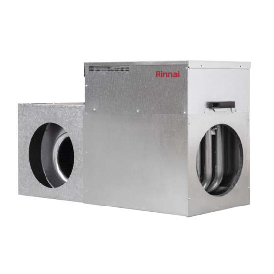
Page 12: Sp5/6 Internal Model Guidelines
4. SP5/6 INTERNAL MODEL GUIDELINES INTERNAL HEATER DIMENSIONS SP6 & SP5 Internal øSa øRa (SP6 MODELS ONLY) Dimension øSa øRa [mm] Table 3. SP5/6 Internal Heater Dimensions (mm) SP615IN 1021 SP623IN 1021 SP623IN-XA INTERNAL MODEL 1021 øSa øRa SP630IN 1070 SP521IN 1021 SP630IN-XA... - Page 13 Method 2: In Ceiling and Under Floor Diagram 2. Heat 800 mm Exchanger Fan Cabinet Minimum Cabinet 750mm Service Clearance Heat Minimum Exchanger Cabinet Cabinet Platform Side View Plan View Method 3: Lay-down Option – In Ceiling Diagram 3. Service 700 mm Clearance Minimum...
-
Page 14: Splitting Internal Model Heaters
SPLITTING INTERNAL MODEL HEATERS The SP5 & SP6 Internal model heaters can be split for ease of installation. To split the heater, follow these simple instructions: a. Remove the heater’s roof after removing the 4 roof screws. b. Disconnect the speed sensor loom from the control board and remove it from the heat exchanger cabinet. c. -
Page 15: Sp5 Internal Models - 100Mm Non-Corrosive Metal Flue
4.5.2 SP5 Internal Models – 100mm non-corrosive metal flue. • Requires a 100mm round single or twin wall non-corrosive metal flue, suitably terminated. • All flues shall have a bolted flue sleeve connection to allow for repairs and/or removal of the appliance. •... -
Page 16: Remote Terminal (Part No. B018384) All Internal Model Applications
4.5.4 Remote Terminal (Part No. B018384) All Internal Model Applications In specific installations, for example under the floor, it is recommended that a remote terminal be used to terminate the flue on the outside wall of the building. Please refer to the instructions supplied with a remote flue terminal. Diagram 6 depicts a typical SP5 underfloor configuration. -
Page 17: Sp5/6 External Model Guidelines
5. SP5/6 EXTERNAL MODEL GUIDELINES HEATER DIMENSIONS Diagram 7. SP6 External FLUE OUTLET GAS INLET øSa øRa CONDENSATE DRAIN POWER LEAD Table 5. SP6 External Heater Dimensions Model (mm) øSa øRa SP623EN 1046 SP623EN-XA 1046 SP630EN 1102 SP630EN-XA 1102 Diagram 8. SP5 External FLUE OUTLET GAS INLET POWER... -
Page 18: Service Clearances
SERVICE CLEARANCES Front/Back A minimum clearance of 500mm must be provided at the side facing away from the house. A minimum clearance of 300mm must be provided at each end of the heater. A minimum clearance of 1000mm must be provided above the heater roof. This clearance must be maintained for the entire surface area of the heater roof. -
Page 19: Installation Of Flue Terminal
INSTALLATION OF FLUE TERMINAL The flue terminal for External models is supplied inside the heater under the roof. On one end of heater you will find the flue outlet socket under an installer instruction label. • Remove the label and insert the flue terminal firmly into the flue outlet socket in the correct orientation to ensure the flue gases are expelled away from the house (refer to Diagram 10). -
Page 20: Flue Terminal Clearances
FLUE TERMINAL CLEARANCES Heaters that are installed outside the house should be positioned so that, when measured from the edges of the flue, the following minimum clearances exist, which are in accordance with AS/NZS 5601: 75mm • Out from the wall against which it is mounted. •... -
Page 21: Thermistor Installation
6. THERMISTOR INSTALLATION SP5 & SP6 INSTALLATION OF THERMISTOR All SP heaters are supplied with a remote thermistor assembly. The thermistor must be installed in the supply air duct, between 1m to 3m away from the heater, but never beyond the first Branch Take Off (BTO) fitting. Note: Where an Add-On air conditioning indoor evaporator coil is installed, the thermistor must be located in the discharge air pop of the indoor coil. -
Page 22: Condensate Removal
7. CONDENSATE REMOVAL All SP6 models have a condensate drain outlet. A fitting and clamp are provided loosely beneath the heater lid for connection to the drain (refer to Diagram 13). • For External models, the outlet is located in the bottom corner below the gas supply connection point. •... -
Page 23: Zoning And Add-On
8. ZONING AND ADD - ON SP5 & SP6 ADAPTIVE ZONING AND ADD - ON AIR CONDITIONING SP5 and SP6 heaters can be configured for zoning and/or Add-On Refrigerative Air Conditioning. There are three 24 Vac relays on the heater’s control module, which can be configured for either three zone motors, or two zone motors and Add-on refrigerative air-conditioning control as shown in Diagram 14 below. -
Page 24: Ducting
9. DUCTING Good duct design and sizing are essential to every Central Heating system. Use the Product Sizing Guide and technical data within this manual for the best results and follow these guidelines: • Ductwork should be well insulated and airtight and have a minimum insulation rating of R1.0 (R1.5 in some areas). -
Page 25: Outlet Guide
10. OUTLET GUIDE The outlet chart (Table 8 on page 26) provides recommendations based on using the Product Sizing Guide or a system designed using accepted design principles. These figures also relate to typical size registers and diffusers used on domestic heating systems i.e. 300mm x 100mm floor registers and 150mm round ceiling diffusers, with 150mm ductwork connection. - Page 26 Table 8. Outlet Register Chart Airflow Rate Maximum No. Typical No. Minimum No. (Adaptive Zoning) System Model (L/s) Ceiling Outlets Floor Outlets Floor/Ceiling Minimum No. Outlets Floor/Ceiling Outlets SP6 Heaters – External SP623EN SP623EN XA SP630EN SP630EN XA SP6 Heaters – Internal SP615IN SP623IN SP623IN-XA...
-
Page 27: Thermostat Installation
11. THERMOSTAT INSTALLATION All SP heating systems can be controlled by various Thermostats, the Networker is detailed below. A Thermostat inside the house is wired to the control module in the heater. The Thermostat monitors the temperature in the house, and switches the system ON and OFF in order to maintain a set temperature. -
Page 28: Connect Multiple Heaters To A Networker
Wiring a Networker to a StarPro Heater a. Run a twin wire cable from the heater to the networker (for example, figure-eight cable, 0.75mm b. Remove the backing plate from the Networker by unclipping it at the sides. c. Draw the wires from the wall cavity and feed them through the opening in the backing plate. d. -
Page 29: Change A Networker From Slave To Master
a. Mount the Networkers in their ideal locations and connect the wiring as shown in Diagram 19. b. Determine which networker will be the Master and which will be the slave. There must be a Master and Slave Networker for a dual Networker system to operate correctly. All Networkers come set as Masters by default, which means only the Slave Networker needs to be configured. -
Page 30: Commissioning And Control Settings
12. COMMISSIONING AND CONTROL SETTINGS All of these heaters have been factory tested, but should be commissioned and adjusted in accordance with the following instructions to ensure efficient and optimal heating performance. Remember: • Mains power must be switched OFF before any wiring is touched. •... -
Page 31: Installer Parameters - Control Lcd Display Settings
12.2 INSTALLER PARAMETERS – CONTROL LCD DISPLAY SETTINGS Table 9. Heater Installer Parameters – SP5 and SP6 DISPLAY DESCRIPTION HEATING: MAXIMUM FAN SPEED SETTING The number displayed is the default fan speed setting. That is, the fan RPM setting for normal heating operation. This setting can be adjusted from 500 to 1350 and should be set to meet the installation airflow requirements. -
Page 32: Sp5 & Sp6 Commissioning Instructions
12.3 SP5 & SP6 COMMISSIONING INSTRUCTIONS With a correctly designed and installed ducted system, generally, the balancing damper in an outlet should be initially set as follows: • Living areas: 100% open • Bedrooms: 50% open • Bathrooms, ensuite and laundry: 25% open. 12.3.1 Initial Ignition and Gas Inlet Pressure Check •... -
Page 33: Final Checks (Sp5 And Sp6 Heaters)
For example, a Certificate of Compliance and Certificate of Electrical Safety. Note: Assist the customer with filling in the Warranty Details on the company website: http://www.rinnai.com.au or www.brivis.com.au and follow the links. Brivis Ducted Gas Heater IM... -
Page 34: Technical Specifications
13. TECHNICAL SPECIFICATIONS Table 10. Minimum Gas Input Heat Output Airflow @ Total Static Pressure Maximum Recommended Fan Motor Duct MJ/hr (L/s) Total Recommended Return Opening Connection Weight Models Maximum Add-On Cooling Pop Sizes (kg) Current (A) Capacity No Filter With Filter Power Current... - Page 35 NOTES Brivis Ducted Gas Heater IM...
- Page 36 Tel: 1300 555 545* Fax: 1300 555 655 Monday to Friday, 8.00 am to 5.00 pm EST. *Cost of a local call higher from mobile or public phones. For further information visit www.rinnai.com.au or email enquiry@rinnai.com.au innai New Zealand Ltd...
Need help?
Do you have a question about the Brivis StarPro SP5 Series and is the answer not in the manual?
Questions and answers