
Related Manuals for Rinnai Brivis CC315 Series


Summary of Contents for Rinnai Brivis CC315 Series
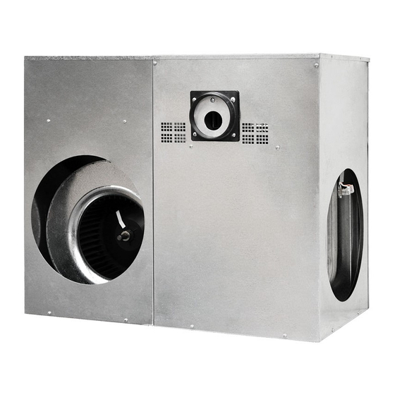
- Page 1 Brivis Models: CC315 CC320 CC325 CC330 Compact Classic Ducted Gas Heater Installation Manual...
- Page 2 This appliance must be installed in accordance with: • Manufacturer’s Installation Instructions • Current AS/NZS 3000, AS/NZS 5601, AS/NZS 5141 • AS 4254, HB 276-2004 • Local Regulations and Municipal Building Codes including local OH&S requirements This appliance must be installed, maintained and removed only by an Authorised Person.
-
Page 3: Table Of Contents
Table of Contents Warnings and Important Information Scope Compact Classic Heaters ..........................5 Installer Due Diligence for Changeovers ......................5 Definitions .................................. 6 Disclaimer .................................. 6 General Product Guidelines Application and Sizing ............................. 7 Unpacking the Heater ............................. 7 Unloading or Lifting the Heater ........................7 Service Connection Guidelines ........................ -
Page 4: Warnings And Important Information
WARNINGS AND IMPORTANT INFORMATION READ ALL INSTRUCTIONS BEFORE USING THE APPLIANCE. Always comply with the following precautions to avoid dangerous situations and to ensure WARNING optimum performance. Failure to carefully read and follow all instructions in this manual can result in equipment malfunction, property damage, personal injury and/or death. -
Page 5: Scope
1. SCOPE This installation manual is intended to be used as a guideline for the installation of Gas Fired Central Heaters. It covers only the installation and commissioning of the heater and the allowable flueing configurations. Although recommended return air grilles and allowable duct outlet quantities are specified, it does not cover the actual ducting design required to suit the specific installation. -
Page 6: Definitions
DEFINITIONS Shall Indicates a mandatory requirement of this manual. Should Indicates a recommended requirement of this manual. Any deviations from these instructions may, at the discretion of the manufacturer, void the warranty. As a result, the customer and/or installer may be charged a fee for non-product warranty related call outs. Also note that failure to comply with these instructions may preclude company service personnel from being able to service the unit. -
Page 7: General Product Guidelines
2. GENERAL PRODUCT GUIDELINES MANDATORY INSPECTION PRIOR TO INSTALLATION Immediately report any damage or discrepancies to your appliance supplier. This appliance has been IMPORTANT inspected and tested at the time of manufacture and packaging, and was released for transportation without known damage. Upon receipt, inspect the exterior for evidence of rough handling in shipment. Ensure that the appliance is labelled correctly for the gas, electrical supply, or other services it is intended to be connected to. -
Page 8: Service Connection Guidelines
SERVICE CONNECTION GUIDELINES 2.4.1 Gas Inlet Connection • All piping must be in accordance with AS/NZS 5601 and any local gas regulations. • The connection point for the heater is a male G3/4 compression fitting to AS 3688. • A gas cock shall be fitted in the gas line adjacent to the heater and in a convenient location so it can be turned OFF quickly and easily. -
Page 9: Removal Of L-Shaped Lid
REMOVAL OF L - SHAPED LID To remove the L-Shaped lid: • Remove all screws securing the lid. • Disengage the short return face of the lid as shown in Diagram 1. • Lift the lid up and off to access the controls as shown in Diagram 2. •... -
Page 10: Ventilation Calculations
VENTILATION CALCULATIONS For installation of internal heaters in a room, enclosure, residential garage, or plant room with natural ventilation conditions, ensure adequate ventilation is available by utilising the following formulae: Installation of a gas appliance in a room or enclosure for properties approved for construction prior to 31st March 2014 a. -
Page 11: Heater Dimensions And Clearances
3. HEATER DIMENSIONS AND CLEARANCES COMPACT CLASSIC Diagram 3. Heater Dimensions GAS INLET THERMOSTAT WIRES ØSa POWER LID FLUE OUTLET Ø 100mm ØRa Table 2. Compact Classic Heater Dimensions (mm) MODEL øSa øRa CC315I V2 CC320I V2 CC320IXA V2 CC325I V2 CC325IXA V2 CC330I V2 CC330IXA V2... -
Page 12: Service Clearances
SERVICE CLEARANCES Method 1 - In Ceiling Diagram 4. 50 mm Minimum (vertical clearance) 200 mm Minimum 750mm 300mm (vertical clearance) Minimum Minimum Heat Controls Exchanger Tray Position Cabinet Cabinet 750mm Service Clearance Minimum Platform Side View Plan View Note: Heater shall be positioned in the above orientation only for service access. Method 2 - In Ceiling and Under Floor Diagram 5. -
Page 13: Splitting Compact Classic Heaters
Method 3 - Under Floor Diagram 6. 200 mm Minimum 750mm 300mm (vertical clearance) Minimum Minimum FLUE OUTLET Heat Exchanger Minimum 20mm Cabinet Cabinet rise per 1 metre run Controls 750mm Tray Position Service Clearance Minimum Platform Plan View Side View SPLITTING COMPACT CLASSIC HEATERS The Compact Classic model heaters can be split in half to allow for ease of installation. - Page 14 Diagram 8. Installation of Alternative Pop Position 1. Remove all eight screws securing the Blank Panel. 4. Remove the two bottom screws from the side Pop Panel. Blank panel Remove screws 2. Remove Blank Panel from the appliance. 5. Secure Blank Panel to open fan side of the appliance with remaining eight screws.
-
Page 15: Flue Instructions
FLUE INSTRUCTIONS 3.5.1 General • All flues must be installed in accordance with AS 5601 Gas installation Code • All horizontal flues must have a minimum rise of 20mm per 1m run • Horizontal flues terminating on a wall must be at least 300mm above ground level •... -
Page 16: Wiring Diagram
WIRING DIAGRAM Diagram 10. CC3 to Thermostat Wiring Diagram T/STAT WIRING THE BRIVIS PROGRAMMABLE THERMOSTAT ( ADD - ON & FAN ONLY ) The Classic control board does not have provision for “Add-On” cooling or “Fan Only” operation. For “Add-On” cooling or “Fan Only”... - Page 17 Diagram 11. Brivis Ice Add-On Schematic - Typical HEATER Heater Programmable 240V Control Active Thermostat Board Terminal Relay Block B063283 Brown Blue Fan speed terminal block White Relay Wires To Add-On Cooling Unit PCB Wires For connection refer to the installation manual Field Supplied Wires accompanying the Add-On cooling unit.
-
Page 18: Ducting Information
4. DUCTING INFORMATION Good duct design and sizing are essential to every Central Heating system. Use the Product Sizing Guide and technical data within this manual for the best results and follow these guidelines: • Ductwork should be well insulated and airtight and have a minimum insulation rating of R1.0 (R1.5 in some areas). -
Page 19: Outlet Chart Information
5. OUTLET CHART INFORMATION The outlet chart (Table 4) provides recommendations based on the Product Sizing Guide or a system designed using accepted design principles. The calculations use the typical size of registers and diffusers used on domestic heating systems (300mm x 100mm floor registers and 150mm round ceiling diffusers) with 150mm ductwork. For all systems, the minimum number of outlets, the outlet grille and the damper in the duct must all remain fully open if the heater is to operate properly without overheating. -
Page 20: Commissioning And Control Settings
6. COMMISSIONING AND CONTROL SETTINGS All of these heaters have been factory tested, but should be commissioned and adjusted in accordance with the following instructions to ensure efficient and optimal heating performance. Remember: • Mains power must be switched OFF before any wiring is touched. •... -
Page 21: Setting Fan Speed
Note: The temperature of the warm air at any outlet should not be more than 45º C above the return air temperature. Note: Assist the customer with filling in the Warranty Details on the company website: http://www.rinnai.com.au or www.brivis.com.au and follow the links. Brivis... -
Page 22: Technical Specifications
7. TECHNICAL SPECIFICATIONS Table 5. Compact Classic Technical Specifications Minimum Gas Input Heat Output Airflow @ Total Static Pressure Maximum Recommended Fan Motor Duct MJ/hr (L/s) Total Recommended Return Opening Connection Weight Model Maximum Add-On Cooling Pop Sizes (kg) Current (A) Capacity No Filter With Filter... - Page 23 NOTES Brivis Ducted Gas Heater IM...
- Page 24 Tel: 1300 555 545* Fax: 1300 555 655 Monday to Friday, 8.00 am to 5.00 pm EST. *Cost of a local call higher from mobile or public phones. For further information visit www.rinnai.com.au or email enquiry@rinnai.com.au innai has a Service and Spare Parts network with...
Need help?
Do you have a question about the Brivis CC315 Series and is the answer not in the manual?
Questions and answers