Sign In
Upload
Manuals
Brands
Challenge Manuals
Trimmer
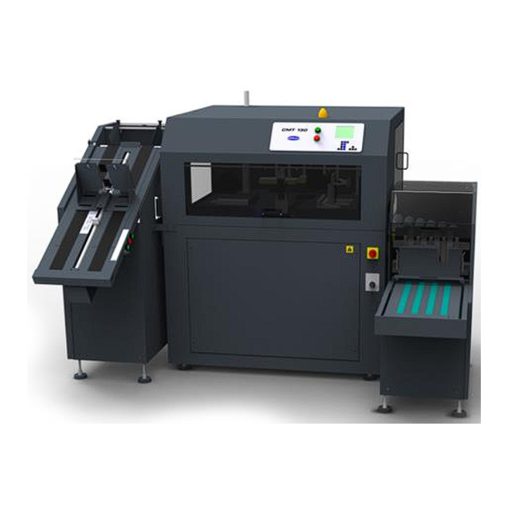
CMT-130
Challenge CMT-130 Manuals
Manuals and User Guides for Challenge CMT-130. We have
2
Challenge CMT-130 manuals available for free PDF download: Service Manual, Installation And Operator's Manual
Challenge CMT-130 Service Manual (226 pages)
Book Trimmer
Brand:
Challenge
| Category:
Trimmer
| Size: 13 MB
Table of Contents
Introduction
2
Notice
2
Safety
3
Revision Control List
4
Table of Contents
5
About this Manual
7
Organization
7
Symbology and Nomenclature
7
Power Lockout Procedure
8
1 Service Call Procedures
9
Contents
9
Introduction
9
Service Escalation Policy
9
How to Order Parts
9
2 Status Indicator Raps
11
Contents
11
Introduction
11
RAP 2.1 Fault Entry
12
RAP 2.2 Final Actions/System Checks
13
RAP 2.3 Faults with Error Messages
14
RAP 2.4 Other Faults (no Error Message)
18
RAP 2.5 Input Power
21
RAP 2.6 DC Power
23
RAP 2.7 Display Backlight
24
RAP 2.8 Enclosure Lights
25
RAP 2.9 Cooling Fans
26
RAP 2.10 Status Light
27
RAP 2.11 Door Interlocks
28
RAP 2.12 Input Door Interlocks
29
RAP 2.13 Interlock Test
30
RAP 2.14 Interlock Relay
31
RAP 2.15 Start/Remote Cut Buttons
32
RAP 2.16 E-Stop/Remote E-Stop Buttons
33
RAP 2.17 Starter Circuit
34
RAP 2.18 Pump Relay
35
RAP 2.19 Proportional and Dump Valves
36
RAP 2.20 Cut Valve
38
RAP 2.21 Shutdown Relay
39
RAP 2.22 Servo Drive Initialization
40
RAP 2.23 Servo Drive System
41
RAP 2.24 Pneumatic Pressure Switch
42
RAP 2.25 Jogger Cylinder
43
RAP 2.26 Gripper Clamp Cylinder
44
RAP 2.27 Gripper Rotator Lock Cylinder
45
RAP 2.28 Elevator Pusher Cylinder
46
RAP 2.29 Knife Shift Cylinders
47
RAP 2.30 Gripper Lift Cylinder
48
RAP 2.31 Registration Plate Extend Cylinder
49
RAP 2.32 Book Lift Air Blast
50
RAP 2.33 Knife Latch Cylinder
51
RAP 2.34 Scrap Air Blast
52
RAP 2.35 Book Gate Cylinder
53
RAP 2.36 Face Jog Cylinder
54
RAP 2.37 Left and Right Clamp Cylinders
55
RAP 2.38 Tilt In-Feed Cylinders
56
RAP 2.39 Internal Conveyor Motor
57
RAP 2.40 Registration Assembly Motor
58
RAP 2.41 Rotary Gripper Motor
59
RAP 2.42 In-Feed Motors
60
RAP 2.43 Elevator Motor
61
RAP 2.44 Out-Feed Conveyor Motor
62
RAP 2.45 Knife Latch Sensor
63
RAP 2.46 Book in Position Sensor
64
RAP 2.47 Jogger Retract Sensor
65
RAP 2.48 Registration Preset Sensor
66
RAP 2.49 Face Jog Sensors
67
RAP 2.50 Rotator Preset Sensor
68
RAP 2.51 Knife Position Sensor
69
RAP 2.52 Knife up Sensor
70
RAP 2.53 Knife Slow-Down Sensor
71
RAP 2.54 Knife down Sensor
72
RAP 2.55 In-Feed Sleep Mode Sensor
73
RAP 2.56 In-Feed Conv. Book-On-Tilt Sensors
74
RAP 2.57 Book in Elevator Sensor
75
RAP 2.58 Elevator Lift Plate Sensor
76
RAP 2.59 Book at Top of Elevator Sensor
77
RAP 2.60 Book out of Elevator Sensor
78
RAP 2.61 Out-Feed Accessory Full Sensor
79
3 Book Quality
81
Contents
81
Introduction
81
BQ 3.1 Burr Marks
82
BQ 3.2 Jagged Bottom Cover
82
BQ 3.3 Burr Marks/Jagged Cover
82
BQ 3.4 Rectangular Crease Lines
83
BQ 3.5 Linear Crease Lines
83
BQ 3.6 Draw
83
BQ 3.7 All Sheets Not Cut
84
BQ 3.8 Book Not Square
84
4 Repair/Adjustment Procedures
85
Contents
85
Introduction
85
REP 4.1 Cut Stick Replacement
86
REP 4.2 Knife Replacement
87
REP 4.3 Knife Depth Adjustment
90
ADJ 4.4 Lubrication
91
REP 4.5 Slide Tape
92
ADJ 4.6 Accuracy Adjustment
93
ADJ 4.7 Squaring Adjustment
94
ADJ 4.8 Timing and Conveyor Belts
95
ADJ 4.9 External Conveyors Belt Check
96
ADJ 4.10 Conveyor Belt Adjustment
97
REP 4.11 Oil / Filter Change
98
REP 4.12 Air Filter Change
99
ADJ 4.13 Hydraulic System Pressure
100
ADJ 4.14 Counterbalance Valve
101
ADJ 4.15 Book Underside Air Lift
102
ADJ 4.16 Knife Gib Adjustment
103
ADJ 4.17 Knife Latch
104
ADJ 4.18 Clamp Pressure Adjustment
105
ADJ 4.19 Gripper Clamp Pressure
106
ADJ 4.20 Face Jog Pressure
107
ADJ 4.21 Face Jog Adjustment
108
REP 4.22 Main PWB Replacement
109
ADJ 4.23 Elevator Pusher Height
110
ADJ 4.24 Elevator Shelf Synchronization
111
5 Parts List
113
Contents
113
Introduction
113
5.1 Main Assembly 59000 (1/12)
114
5.2 Main Assembly 59000 (2/12)
115
5.3 Main Assembly 59000 (3/12)
116
5.4 Main Assembly 59000 (4/12)
117
5.5 Main Assembly 59000 (5/12)
118
5.6 Main Assembly 59000 (6/12)
119
5.7 Main Assembly 59000 (7/12)
120
5.8 Main Assembly 59000 (8/12)
121
5.9 Main Assembly 59000 (9/12)
122
5.10 Main Assembly 59000 (10/12)
123
5.11 Main Assembly 59000 (11/12)
124
5.12 Main Assembly 59000 (12/12)
125
5.13 Registration Asm. 56311-3
126
5.14 Conveyor Drive 56374-1
127
5.15 Power Panel EE-3306-1 (1/2)
128
5.16 Power Panel EE-3306-1 (2/2)
129
5.17 Power Panel - 50Hz EE-3310
130
5.18 Control Console EE-3310
131
5.19 Pneumatic Diag. 59000-P (1/2)
132
5.20 Pneumatic Diag. 59000-P (2/2)
133
5.21 Pneu. Manifold Asm. 59012-1
134
PL 5.22 Hydraulic Power Unit 59010
135
5.23 Hydraulic Power Unit 59010-1
136
PL 5.24 Manifold Assembly 59011
137
PL 5.25 Hydraulic Schem. 59010-S
138
5.27 Elevator 56421 (1/7)
140
5.28 Elevator 56421 (2/7)
141
5.29 Elevator 56421 (3/7)
142
5.30 Elevator 56421 (4/7)
143
5.31 Elevator 56421 (5/7)
144
5.32 Elevator 56421 (6/7)
145
5.33 Elevator 56421 (7/7)
146
PL 5.34 Idler 56446
147
PL 5.35 Pusher 56483
148
5.36 Elev. Electrical EE-2980-1
149
PL 5.37 Elev. Pneumatics 56421-P
150
5.38 Tilt Conveyor 56600 (1/8)
151
5.39 Tilt Conveyor 56600 (2/8)
152
5.40 Tilt Conveyor 56600 (3/8)
153
5.41 Tilt Conveyor 56600 (4/8)
154
5.42 Tilt Conveyor 56600 (5/8)
155
5.43 Tilt Conveyor 56600 (6/8)
156
5.44 Tilt Conveyor 56600 (7/8)
157
5.45 Tilt Conveyor 56600 (8/8)
158
5.46 Tilt Conv. Elec. EE-2993-3
159
PL 5.47 Tilt Conv. Pneum. 56600-P
160
5.48 Long Hand-Feed Conv. 56413 (1/3)
161
5.49 Long Hand-Feed Conv. 56413 (2/3)
162
5.50 Long Hand-Feed Conv. 56413 (3/3)
163
5.51 Long Hand-Feed Electrical EE-2985-1
164
PL 5.52 Std. Hand-Feed Conv. 59200
165
5.53 Std Hand-Feed Elec. EE-3342
166
5.54 Exit Conv. 56420 (1/3)
167
5.55 Exit Conv. 56420 (2/3)
168
5.56 Exit Conv. 56420 (3/3)
169
5.57 Exit Conv. Elec. EE-2979-3
170
5.58 Conveyor Drive Asm. 56340-1
171
5.59 Conveyor Drive Asm. 56340-2
172
6 General Procedures/Information
173
Contents
173
Introduction
173
GP 6.1 Retrieve Recent Error Messages
174
GP 6.2 Input Diagnostics (Sensor Data)
175
GP 6.3 Output Diagnostics
177
GP 6.4 Input/Output Leds
179
GP 6.5 Input Testing
180
GP 6.6 Output Testing
181
GP 6.7 Software Upgrade/Replacement
182
GP 6.8 Software Re-Initialization
183
GP 6.9 Proximity Sensors
184
GP 6.10 Retro-Reflective Sensors
185
GP 6.11 Diffuse Sensors
186
GP 6.12 Micro-Switches
187
GP 6.13 Hirschmann Connectors
188
GP 6.14 Contact Blocks
189
GP 6.15 Speed-Control Air Valves
190
GP 6.16 Principles of Operation
191
GP 6.17 Specifications
194
GP 6.18 Book Size Chart
195
GP 6.19 Scheduled Maintenance
196
GP 6.20 Change Tags
197
7 Wiring Data
199
Contents
199
Introduction
199
WD 7.1 Schematic - 230 VAC E-3307-1 (1/9)
200
WD 7.2 Schematic - 120 VAC E-3307-1 (2/9)
201
WD 7.3 Schematic - 27 VAC E-3307-1 (3/9)
202
WD 7.4 Schematic - 18 VAC E-3307-1 (4/9)
203
WD 7.5 Schematic - 9 VAC E-3307-1 (5/9)
204
WD 7.6 Schematic - 35 VDC E-3307-1 (6/9)
205
WD 7.7 Schematic - 24 VDC E-3307-1 (7/9)
206
WD 7.8 Schematic - 15 VDC E-3307-1 (8/9)
207
WD 7.9 Schematic - 5 VDC E-3307-1 (9/9)
208
WD 7.10 Plug Connections to PWB EE-2939-2
209
WD 7.11 Schematic - Elevator EE-2980-1
210
WD 7.13 Schematic - Long In-Feed EE-2985-1
212
WD 7.14 Schematic - Std In-Feed EE-2985-1
213
WD 7.16 Interconnection Diagram E-3308-1
215
WD 7.17 Fuse Chart S-1781-193
216
8 Installation
217
Contents
217
Introduction
217
8.1 Shipping Claims
218
8.2 Unpacking
218
8.3 Moving
218
8.4 In-Feed Setup
219
8.5 Trimmer Setup
222
8.6 Out-Feed Setup
222
8.7 Power Hookup
223
8.8 Air Hookup
225
8.9 Cleaning
225
Advertisement
Challenge CMT-130 Installation And Operator's Manual (65 pages)
Book Trimmer
Brand:
Challenge
| Category:
Trimmer
| Size: 4 MB
Table of Contents
Table of Contents
3
Introduction
5
Contents
5
Warranty Information
6
Warning Label Definitions
7
Note Definitions
7
Safety
7
Power Lockout Procedure
8
Packing List
9
Base Machine/Options
10
Standard Accessories
11
Consumables
12
Optional Items
12
Specifications
13
Book Size Chart
14
General Locations
15
Trimmer Front and Back Views
15
Site Specifications
16
2. Installation Guide
26
Contents
26
Installation Guide
26
Introduction
26
In-Feed Setup
27
Moving
27
Shipping Claims
27
Unpacking
27
In-Line In-Feed Option Setup
28
Long Hand-Feed Option Setup
30
Pile Feeder Option Setup
30
Standard Hand-Feed Option Setup
30
Exit Conveyor Option Setup
31
Out-Feed Setup
31
Trimmer Setup
31
Vertical Stacker Option Setup
31
Exit Ramp Option Setup
32
Power Hookup
32
Power Hookup Procedure
32
Air Hookup
33
Compressed Air Requirements
33
Air Hookup Procedure
34
Cleaning
34
3. Operator's Guide
36
Contents
36
Introduction
36
Operator's Guide
36
Console Descriptions
37
Programming
37
Key Descriptions
38
Using the Keypad
39
User Interface Map
40
Improper Wiring
41
Initialization
41
Jobs
41
Power up
41
Creating a Job
42
Editing a New Job
42
Editing an Existing Job
42
Entering or Editing a Job Name
42
Erasing a Job
43
Job Options
43
Lock/Unlock a Job
43
Closing a Job
44
Running a Job
44
Status Messages
45
Example Job
49
4. Routine Tasks
52
Introduction
52
Routine Tasks
52
Section Contents
52
Book Underside Air Lift
53
Changing the Cut Stick
53
Cut Stick
53
Waste bin
53
Knife
54
Knife Change
54
Knife Depth Adjustment
56
Check Pressure Switch
57
Knife Sharpening Rules
57
Safety Systems Check
57
Safety Check-Off Sheet
59
Book Quality
60
Contents
60
Introduction
60
Burr Marks
61
Burr Marks/Jagged Cover
61
Jagged Bottom Cover
61
Draw
62
Linear Crease Lines
62
Rectangular Crease Lines
62
All Sheets Not Cut
63
Book Not Square
63
Advertisement
Related Products
Challenge CMT 330
Challenge CMT-330TC
Challenge CMT-130TC
Challenge CMT-330TC-A
Challenge Challenge
Challenge Portable Air Conditioner
Challenge CH18V2
Challenge CH-EH3
Challenge CEBLV2840
Challenge Compass
Challenge Categories
Paper Cutters
Trimmer
Drill
Lawn Mower
Air Conditioner
More Challenge Manuals
Login
Sign In
OR
Sign in with Facebook
Sign in with Google
Upload manual
Upload from disk
Upload from URL