
Subscribe to Our Youtube Channel
Related Manuals for Fike 10-2983

Summary of Contents for Fike 10-2983
- Page 1 PRODUCT MANUAL Output Analyzer P/N 10-2983 Doc. P/N 06-905 Rev. 1 / December 2018 SOLUTIONS Fire Protection Explosion Protection Overpressure Protection Pressure Activation...
- Page 3 Fike products. Do not use any Fike products for any application for which it is not intended. Fike shall not be in any way liable for any damages or losses incurred by you or third parties arising from the use of any Fike product for which the product is not intended by Fike.
-
Page 5: Table Of Contents
Table of Contents 1.0 GENERAL ................................. 1 2.0 FEATURES ................................3 3.0 APPROVALS ................................3 4.0 SAFETY INFORMATION ............................3 5.0 BATTERY LIFE ................................4 6.0 CONTROLS/INTERFACE ............................4 6.1. Navigation Menu ............................5 7.0 EPC TESTING................................5 7.1. EPC Operational Overview ..........................5 7.2. - Page 6 List of Figures Figure 1.0-1 Output Analyzer…………………………………………………………………………………………………………………………………..1 Figure 6.0-1 Output Analyzer Controls and Interface……………………………………………………………………………………………….2 Figure 7.3.1-1 EPC Series Firing Circuit Activation Current………………………………………………………………………………………..6 Figure 7.3.2-1 EPC Series Firing Circuit Supervisory Current Test………………………………………………………………………………8 Figure 7.3.3-1 Field Wiring Activation Current Test…………………………………………………………………………………………………..9 Figure 8.3-1 IRM Circuit Activation Current Test…………………………………………………………………………………………………..11 Figure 9.3-1 Fire ARM Circuit Activation Current Test……………………………………………………………………………………………..13 Figure 10.3-1 EP ARM Series Firing Circuit Activation Current Test…………………………………………………………….…………...15 List of Tables...
-
Page 7: General
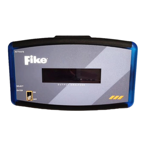
Casing: ABS plastic Figure 1.0-1 Output Analyzer The Fike Output Analyzer (10-2983) is a compact, rechargeable, hand-held device that is designed to be used by Fike factory-trained and certified service technicians to test and verify operation of the following Fike releasing components: Explosion Protection Controller (EPC)*, P/N E10-0066. - Page 8 Directive 2014/30/EU, the unit shall not be used while charging the battery and the battery charger used for charging the device shall be compliant with the requirements of EN61326-1. The 1-Ohm Resistor is included in the E10-070 kit purchased by EP Service Technicians, of which the 10-2983 Output Analyzer is a part.
-
Page 9: Features
STATIC DISCHARGE – Use a grounding strap to eliminate static discharge sources prior to working with GCAs. IMPORTANT: Pack and safely store the Fike Output Analyzer when not in use. Do not allow the Analyzer to remain connected to live circuitry, as this will reduce battery life. -
Page 10: Battery Life
On initial power up, the battery charge will display for three (3) seconds; this will help you gauge whether you can complete all tests on the current charge. Next, the panel will display “Fike Analyzer Select Tool Use.” Once you see this message, press and release the SELECT button to view the main menu. -
Page 11: Navigation Menu
6.1. Navigation Menu Press and release the SELECT button to advance through the menu options on the front LCD panel. Continue to press and release the SELECT button until you reach the desired function. The navigation menu functions in a loop and there is no back button, so if you advance past an option, you’ll need to press and release the SELECT button to loop back to the desired option. -
Page 12: Interpreting Epc Measured Results
7.2. Interpreting EPC Measured Results Once you’ve used the Analyzer to test the activation current supplied by an EPC, the Analyzer will display the results on the front panel as either EPC PASSES or REPLACE EPC. When the Analyzer is used to test the supervisory current supplied by the EPC, it will display the supervisory current reading in milliamps. - Page 13 Battery at 100% 9. SELECT TOOL USE displays next. Press and release the SELECT button until EPC TOOL displays. Press ENTER to select this option. The device will prompt you to connect the leads. Fike Analyzer EPC Analyzer Select Tool Use Connect Leads 10.
-
Page 14: Test 2: Epc Supervisory Current Test
7.3.2. Test 2: EPC Supervisory Current Test This Output Analyzer test verifies the acceptability of the supervisory current supplied by the EPC’s series firing circuit. The Analyzer comes with jumpers and test leads that are used to perform this test. To get started: Power down the EPC. -
Page 15: Test 3: Epc Field Test
7.3.3. Test 3: EPC Field Test This Output Analyzer test verifies that the acceptable activation current is being supplied by the EPC to the field devices through series firing circuit field wiring. The Analyzer comes with jumpers and test leads that are used to perform these tests. -
Page 16: Test 4: Field Wiring Supervisory Current Test
9. With the leads connected and the appropriate test jumper installed, the Analyzer will initiate a 30-second countdown timer to ensure the internal series firing circuit on the EPC is charged and ready to fire. The Analyzer will display a countdown to indicate when the time delay has expired and the EPC is ready for testing. Wait: Charging Countdown: 30 10. -
Page 17: Irm Testing
8.0 IRM TESTING 8.1. IRM Operational Overview The Output Analyzer can be used to perform two important testing functions associated with the IRM firing circuit. The first testing function assesses the IRM’s ability to supply the correct current (amps) required to activate the actuator devices connected to the firing circuit;... -
Page 18: Fire Arm Testing
Enable the release circuit and IRM with the Analyzer installed (one per IRM or repeat testing for each one at a time). Wait 60 seconds to allow the capacitors time to charge. If the panel does not immediately return to normal, reset the panel to a normal state. -
Page 19: Interpreting Fire Arm Measured Results
9.2. Interpreting Fire ARM Measured Results Once you’ve used the Analyzer to test the activation current supplied by the Fire ARM, the Analyzer will display the results on the front panel as either Fire ARM PASSES or Fail REPLACE ARM. When the Analyzer is used to test the supervisory current supplied by the releasing panel or module, it will display the supervisory current reading in milliamps. -
Page 20: Ep Arm Testing
The current reading displays, along with “ARM PASSES” or “FAIL REPLACE ARM.” 5.65 6.1 3.9 2.3 1.78 2.2 2.6 2.8 ARM PASSES FAIL REPLACE ARM NOTE: The upper limit of each test range is provided to help you determine when a component is nearing the end of its useful life and should be replaced. -
Page 21: Ep Arm Testing Procedures
10.3. EP ARM Testing Procedures WARNING! Before you begin, disable the EP Control Panel and shunt all GCA’s (per E06-018-2 and E06-017-2) connected to the system before proceeding! 2. Connect the Analyzer to the EP ARM as shown in Figure 10.3-1 below. Fire (EPC Only) Shunt... -
Page 22: View Memory
EN61326-1. 14.0 TECHNICAL SUPPORT We are confident in the quality and construction of the Fike Output Analyzer, but if you should ever have a problem or question, please feel free to contact us at: Telephone:...
Need help?
Do you have a question about the 10-2983 and is the answer not in the manual?
Questions and answers