
Subscribe to Our Youtube Channel
Related Manuals for TOHO TTM-i4N


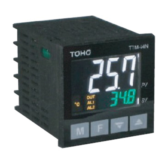
Summary of Contents for TOHO TTM-i4N
- Page 1 Digital Controller TTM‐i4N User’s Manual Contents 1. Precautions upon Usage 2. Name and Function of Parts 3. Installation 3.1 Dimensions 3.2 Installation and Dimensions of Panel Cut 4. Wiring 4.1 Terminal Layout for Wiring 4.2 Caution upon Wiring 5. List of 7-segment Characters 6.
- Page 2 1. Precautions upon Usage Please read this section before use. For the safe use of this product, please take note of the following: This operation manual should be kept by the user of this product. ...
- Page 3 Warning Improper wiring to the equipment may cause a failure, such as fire. Upon completion of wiring, ensure to verify the proper wiring before turning on electricity. Do not turn on electricity until all wiring is complete.
- Page 4 2. Name and Function of Parts Displays the character of current measurement value or setting mode screen. Displays the selected input value of setting value, output value, or setting mode screen. °F Lights up when the setting value is a temperature data with the unit of °F. °C Lights up when the setting value is a temperature data with the unit of °C.
- Page 5 3. Installation 3.1 Dimensions 63 3.2 Installation and Dimensions of Panel Cut Attach the product either vertically (upper surface of the product should be facing up) or horizontally. How to Attach: Place the product into an angle hole of the panel cut and completely insert the attachment from the surface without any gap.
- Page 6 4. Wiring 4.1 Terminal Layout for Wiring 4.2 Caution upon Wiring Warning: Turn the power OFF before wiring to avoid the risk of electric shock. Caution: This product will not perform any control for approximately 4 seconds after turning its power ON (produces no output).Please be careful if you will be using this product as an interlock circuit.
- Page 7 5. List of 7-segment Characters < List of 7-segment Characters > Numbers and alphabets used in parameter symbols and settings are described as follows: 1 2 3 4 5 6 7 8 9 A B C D E...
- Page 8 6. Operation Flow and Parameters 6.1 Display Sections Display Sections Color Description PV Display Section White • Displays measurement values and characters that have been set. SV Display Section Green • Displays setting values and manipulated variables. °F Yellow • Lights up when the setting value is a temperature data with the unit of °F.
- Page 9 6.2 Operation Keys Operation Keys Description M Key • Switches screens. F Key • Executes functions that are being set. 1) Digit Navigation Key (selected digit blinks): Usable in all modes. 2) RUN/READY Key: Usable only in operation mode. Click once to enable the function. 3) AT Start/Stop Key: Usable only in operation mode.
- Page 10 6.3.1 Operation Mode 1. Controlled Temperature Setting 1200 0 ↓M Key **** 2. Priority Screen 1 **** ↓M Key **** 3. Priority Screen 2 **** ↓M Key **** 4. Priority Screen 3 **** ↓M Key **** 5. Priority Screen 4 **** ↓M Key ****...
- Page 11 6.3.2 Protect Setting Mode 1. Protect Level Setting PTLV 0 6.3.3 Priority Screen Parameter Mode 1. Setting Mode Selection Screen SET0 PRI ↓M Key 2. Priority screen 1 setting PRI1 OFF ↓M Key 3.
- Page 12 6.3.4 Input Parameter Mode 1. Setting Mode Selection Screen SET1 INP ↓M Key 2. Input type setting INP 00 ↓M Key 3. PV compensation gain setting PVG 100 ↓M Key 4. PV compensation zero setting PVS ...
- Page 13 6.3.5 Key Function Parameter Mode 1. Setting Mode Selection Screen SET2 KEY ↓M Key 2. Function key function setting FU 00 ↓M Key 3. Key-lock setting LOC 0 ↓M Key 4. Alarm reset ALRS ...
- Page 14 6.3.6 Control Parameter Mode 1. Setting Mode Selection Screen SET3 CNT ↓M Key 2. SV limiter upper limit SLH 1200 ↓M Key 3. SSV limiter lower limit SLL 0 ↓M Key 4. Control mode setting MD ...
- Page 15 ↓ 14. Derivative time setting D ※1 0 ↓M Key 15. Proportional cycle setting for OUT1 T1 ※1 20 ↓M Key 16. Setting of Anti-reset Windup ARW ※1 1100 ↓M Key 17. Operating amout limiter upper limit for OUT1 MLH1 ...
- Page 16 ↓ 29. Operating amout limiter upper limit for OUT2 MLH2 ※4 ※5 1000 ↓M Key 30. Operating amout limiter lower limit for OUT2 MLL2 ※4 ※5 00 M key 33. Setting of the Loop Abnormality Judgment Time of Output 2 LOP2 ...
- Page 17 6.3.7 Event 1 Output Parameter Mode 1. Setting Mode Selection Screen SET4 AL1 ↓M Key 2. Event 1 Function Setting 1 A1F1 000 ↓M Key 3. EV1 alarm upper limit setting A1H ※8 ※9 0 ...
- Page 18 6.3.8 Event 2 Output Parameter Mode 1. Setting Mode Selection Screen SET5 ※12 ※13 AL2 ↓M Key 2. Event 2 Function Setting 1 A2F1 ※12 000 ↓M Key 3. EV2 alarm upper limit setting A2H ...
- Page 19 6.3.9 Timer Parameter Mode 1. Setting Mode Selection Screen SET6 TIME ↓M Key 2. Timer output setting TMO 0 ↓M Key 3. Setting of Timer Function TMF ※18 1 ↓M Key 4. Setting of the Unit of Timer H/M ...
- Page 20 6.3.10 LCD Parameter Mode 1. Setting Mode Selection Screen SET7 LCD ↓M Key 2. Brightness setting LLV 100 ↓M Key 3. Dimming function setting LRFT 0 ↓M Key 4. Dimming Brightness setting LRLV ...
- Page 21 6.4 Parameters 6.4.1 Operation Mode Character Name Description Initial Value Operation Mode Mode that is usually used by PV/SV ControlledTemperature Setting Range: SLL–SLH (SV) Settings Setting Unit: °C or °F Priority Screen 1–9 Displays the screen that is set at Priority Screen. ...
- Page 22 6.4.3 Priority Screen Setting Mode ■ Priority Screen Setting Character Name Description Initial Value Setting Mode Selection Screen Settings about Priority Screen SET0 Priority Screen Setting Mode PRI Priority screen 1 setting Sets the parameter to be displayed on a priority screen Screen 1–9 PRI1 ...
- Page 23 6.4.4 Input Parameter Mode ■Input type setting Character Name Description Initial Value Setting Mode Selection Settings about Input SET1 Screen INP Input Parameter Mode Input type setting Setting Range: 00–06, 10, 11 INP See Input Type Setting Table for detail Input Type Setting Table Setting Connect...
- Page 24 ■PV compensation gain setting /Zero Setting of PV Correction Character Name Description Initial Value Setting Mode Selection Settings about Input SET1 Screen INP Input Parameter Mode PV compensation gain Setting Range: 0.50–2.00 PVG setting Setting Unit: Times PV compensation zero Setting Range: -199–999 or -199.9–999.9 PVS...
- Page 25 [Function] Adds correction value to PV (measurement value). [Sample Setting] In case PV is displayed as 90°Cin an environment where the actual temperature is 100°C, PV can still be adjusted to 100°Cby zero-setting the PV correction to 10 (°C). [Computation formula = 90°C(before PV correction) + 10°C= 100°C] ※...
- Page 26 ■ Setting of PV Filter Character Name Description Initial Value Setting Mode Selection Settings about Input SET1 Screen INP Input Parameter Mode Setting of Input Filter Setting Range: 0.0–99.9 PDF Setting Unit: Second [Function] A function to programmatically realize CR filtering effect by performing a primary delay operation for PV of the input. Filter effect will be set through time constant.
- Page 27 ■ Decimal point setting Character Name Description Initial Value Setting Mode Selection Settings about Input SET1 Screen INP Input Parameter Mode Decimal point setting DP Without Decimal Point With Decimal Point (Disabled for R/S/B thermocouple) Note: Switching °C/ °F may activate the limiter, such as SLH and SLL, and change each setting value.
- Page 28 6.4.5 Key Function Parameter Mode ■ Function key function setting Character Name Description Initial Value Setting Mode Selection Settings about Key Function SET2 Screen KEY Key Function Parameter Mode Function key function Function Settings FU setting *0 No Function *1 Digit Shifting Key *2 RUN/READY Key...
- Page 29 ■ Key Lock Settings Character Name Description Initial Value Setting Mode Selection Settings about Key Function SET2 Screen KEY Key Function Parameter Mode Key-lock setting LOC No Key Lock Lock All Lock Operation Mode ...
- Page 30 6.4.6 Control Parameter Mode ■ Minimum/Maximum Limit of SV Limiter Characte Name Description Initial Value Setting Mode Selection Settings about Control SET3 Screen CNT Control Parameter Mode SV limiter upper limit Setting Range: Minimum setting range-Maximum setting range SLH 1200 ...
- Page 31 ■ Control type setting Character Name Description Initial Value Setting Mode Selection Settings about Control SET3 Screen CNT Control Parameter Mode Control type setting Function CNT 0** Type A 1** Type B 2** Fuzzy Output Type of Output 1 *1* PID Control *2* ON/OFF Control Output Type of Output 2...
- Page 32 ■ Tuning type setting Character Name Description Initial Value Setting Mode Selection Settings about Control SET3 Screen CNT Control Parameter Mode Tuning type setting DIR Reverse Action 0 Direct Action 1 <Reverse Action> ...
- Page 33 ■ Manipulated Variable of Output 1 Character Name Description Initial Value Setting Mode Selection Settings about Control SET3 Screen CNT Control Parameter Mode Manipulated Variable of Display Range: 0.0%–100.0% MV1 Output 1 Setting Range: MLL1–MLH1 ・ It shall be used to monitor the manipulated variable of Output 1 and to set the manipulated variable during manual control. ・...
- Page 34 ■ AT coefficient setting Character Name Description Initial Value Setting Mode Selection Settings about Control SET3 Screen CNT Control Parameter Mode AT coefficient setting Setting Range: 0.1–10.0 ATG Setting Unit: Times Multiplies the coefficient to the value of proportional band that shall be calculated during AT. Note: It is recommended to use the default value for AT coefficient setting parameter.
- Page 35 ■ AT sensitivity setting Character Name Description Initial Value Setting Mode Selection Settings about Control SET3 Screen CNT Control Parameter Mode AT start/stop AT Stop AT Start AT ※ Start or stop AT by pressing the F key. ■...
- Page 36 ■ Integral time setting Character Name Description Initial Value Setting Mode Selection Settings about Control SET3 Screen CNT Control Parameter Mode Integral time setting Setting Range: 0–3600 I Setting Unit: Second Sets the reset time. Reset will not be performed if 0 second is set. In case of heating and cooling controls, both heating and cooling controls commonly use this setting.
- Page 37 ■ Proportional cycle setting for OUT1 Character Name Description Initial Value Setting Mode Selection Settings about Control SET3 Screen CNT Control Parameter Mode Proportional cycle Setting Range: 1–120 T1 ※1 setting for OUT1 Setting Unit: Second ※2 ※1: A default value of which the type of Output 1 is R (Relay Contact Output). ※2: A default value of which the type of Output 1 is P (Voltage Output for SSR Drive).
- Page 38 ■ Operating amout limiter upper limit for OUT1 Character Name Description Initial Value Setting Mode Selection Settings about Control SET3 Screen CNT Control Parameter Mode Operating amout limiter Setting Range: MLL1–100.0 MLH1 1000 upper limit for OUT1 Setting Unit: % It provides a maximum limit for the manipulated variable that was calculated.
- Page 39 ■ Sensitivity setting for OUT1 Character Name Description Initial Value Setting Mode Selection Settings about Control SET3 Screen CNT Control Parameter Mode Sensitivity setting for Setting Range: 0–999 or 0.0–999.9 C1 OUT1 Setting Unit: °C or °F Sets the sensitivity (hysteresis) of the ON/OFF action of output 1.
- Page 40 Sets the position of OFF point (offset for SV) for the ON/OFF operation of direct action. OFF point CP1 0 C1 Sensitivity setting High OFF point CP1 negAtive vAlue C1 Sensitivity setting CP1 OFF-point position C point SV CP1 C point High OFF point CP1 negAtive vAlue C1 Sensitivity setting...
- Page 41 ■ Setting of the Loop Abnormality Judgment Time of Output 1 Character Name Description Initial Value Setting Mode Selection Settings about Control SET3 Screen CNT Control Parameter Mode Setting of Output 1 Loop Setting Range: 0–9999 LOP1 Abnormality Setting Unit: Second Judgment Time...
- Page 42 ■ Setting of the Loop Abnormality PV Threshold of Output 1 Character Name Description Initial Value Setting Mode Selection Settings about Control SET3 Screen CNT Control Parameter Mode Setting of Output 1 Loop Setting Range: 0–999 or 0.0–999.9 TS1 ...
- Page 43 ■ Protection OFF timer time setting for OUT1/Protection ON timer time setting for OUT1 Character Name Description Initial Value Setting Mode Selection Settings about Control SET3 Screen CNT Control Parameter Mode Protection OFF timer Setting Range: 0–99 FDT1 ...
- Page 44 ■ Proportional band setting for OUT2 Character Name Description Initial Value Setting Mode Selection Settings about Control SET3 Screen CNT Control Parameter Mode Proportional band Setting Range: 0.10–10.00 P2 setting for OUT2 Setting Unit: Magnification for Output 1 proportional band Sets the proportional band for Output 2.
- Page 45 ■ Operating amout limiter upper limit for OUT2 Character Name Description Initial Value Setting Mode Selection Settings about Control SET3 Screen CNT Control Parameter Mode Operating amout limiter Setting Range: MLL2–100.0 MLH2 1000 upper limit for OUT2 Setting Unit: % ...
- Page 46 ■ Setting of the Sensitivity of Output 2 Character Name Description Initial Value Setting Mode Selection Settings about Control SET3 Screen CNT Control Parameter Mode Setting of the Sensitivity Setting Range: 0–999 or 0.0–999.9 C2 of Output 2 Setting Unit: °C or °F Sets the sensitivity of output 2.
- Page 47 Sets the position of OFF point (offset for SV) for the ON/OFF operation of reverse action.
- Page 48 Sets the position of OFF point (offset for SV) for the ON/OFF operation of direct action.
- Page 49 ■ Setting of the Loop Abnormality Judgment Time of Output 2 Character Name Description Initial Value Setting Mode Selection Settings about Control SET3 Screen CNT Control Parameter Mode Setting of Output 2 Loop Setting Range: 0–9999 LOP2 Abnormality Setting Unit: Second Judgment Time...
- Page 50 ■ Setting of the Loop Abnormality PV Variation of Output 2 Character Name Description Initial Value Setting Mode Selection Settings about Control SET3 Screen CNT Control Parameter Mode Setting of Output 2 Loop Setting Range: 0-999 or 0.0-999.9 TS2 ...
- Page 51 ■ Setting of the Loop Abnormality PV Variation of Output 2 Character Name Description Initial Value Setting Mode Selection Settings about Control SET3 Screen CNT Control Parameter Mode Protection OFF timer Setting Range: 0-99 FDT2 time setting for OUT2 Setting Unit: Minute Protection ON timer time Setting Range: 0-99...
- Page 52 ■ Enable/Disable Balance-less Bump-less Function Character Name Description Initial Value Setting Mode Selection Settings about Control SET3 Screen CNT Control Parameter Mode Balance-less Bump-less BMP Without balance-less bump-less function Function With balance-less bump-less function ON/OFF Setting If PID control is set, the balance-less bump-less function will be used to prevent the sudden change of the manipulated variable (control output) upon switching the control between auto and manual and to prevent damage to peripherals and bad effect on control system that may be caused by such a sudden change.
- Page 53 ■ Dead band setting Character Name Description Initial Value Setting Mode Selection Settings about Control SET3 Screen CNT Control Parameter Mode Dead band setting Setting Range: -100–100 or -100.0–100.0 DB Setting Unit: °C or °F It moves the proportional band (or sensitivity) of Output 2. If the value is positive, the distance between Output 1 and 2 gets wider.
- Page 54 ■ SV Ramp time setting Character Name Description Initial Value Setting Mode Selection Settings about Control SET3 Screen CNT Control Parameter Mode SV Ramp time setting Setting Range: 0.0–999.9 RMP Setting Unit: °C/min. (or °F/min.) ※ Setting “0.0” will turn the SV ramp OFF Sets the transition of SV per minute upon changing SV.
- Page 55 ■ Control backup function setting Character Name Description Initial Value Setting Mode Selection Settings about Control SET3 Screen CNT Control Parameter Mode Control backup function Setting Range: 0.0–10.0 PWZ setting Setting Unit: °C or °F ※ Setting “0.0” will turn the control backup function OFF Improves the control until it stabilizes by memorizing the reset manipulated variable during the time when the control is in stable condition while performing PID control and reflects the memorized reset manipulated variable to the manipulated variable when the control has recovered from the brownout.
- Page 56 6.4.7 Event □ Output Parameter Mode ■Event 1 Function Setting 1/Event 2 Function Setting 1/Event 1 Maximum and Minimum Limits Setting/Event 2 Maximum and Minimum Limits Setting/Event 1 Sensitivity Setting/Event 2 Sensitivity Setting/Event 1 Delay Time Setting/Event 2 Delay Time Setting Character Name...
- Page 57 It configures Event (1, 2) Function Setting/Event (1, 2) Minimum and Maximum Limits Setting/Event (1, 2) Sensitivity Setting/Event (1, 2) Time Delay Setting. Event (1, 2) Function Setting is a function that compares PV with event setting value and outputs a signal (ON/OFF) to Event Output 1 and 2 once the designated condition is satisfied.
- Page 58 ・ Event Function It runs the event when PV of the input has moved inside the designated operating range of the event. Operating range will be set by event function setting, maximum and minimum limits of event, and event sensitivity. 1.Deviation upper and lower limits 5.Absolute value upper and lower limits 2.Deviation upper limit...
- Page 59 ・Control Mode Interlock Function Interlock Function: It sets the control mode that will run the event function under the control mode interlock function. Combinations with the standby sequence are the following: 1) No Event occurred Event will not occur even when RUN/READY is switched.
- Page 60 ■EV1 alarm function 3 setting/EV2 alarm function 3 setting Character Name Description Initial Value Setting Mode Selection SET4 Screen Settings about Event 1 Output Function AL1 Event 1 Output Parameter Mode Settings about Event 2 Output Function SET5 Event 2 Output AL2 Parameter Mode ...
- Page 61 6.4.8 Timer Parameter Mode ・ Timer Function is a function to make the event occur for a certain period of time or after a certain period of time from the occurrence of a certain trigger. ■ Timer output setting Character Name Description...
- Page 62 ■ Setting of Timer Function Character Name Description Initial Value Setting Mode Selection Settings about Timer SET6 Screen TIME Timer Parameter Mode Setting of Timer Function TMF Automatic Start (ON Delay) Manual Start (ON Delay) ...
- Page 63 ・ OFF Delay When the timer starts to count itself up by turning the power ON, the control begins/turns output of Event 1/2 OFF. (Can start manually after the counting) Manual Start (ON Delay, OFF Delay) ・ ON Delay ...
- Page 64 Event 1/2 Start (ON Delay, OFF Delay) ・ ON Delay When the timer starts to count itself up with the occurrence of the event, the control begins/turns output of Event 1/2 ON. (Can start manually after the counting) ・...
- Page 65 ■ Setting of the Unit of Timer Character Name Description Initial Value Setting Mode Selection Settings about Timer SET6 Screen TIME Timer Parameter Mode Setting of the Unit of H/M Hr. & Min. Timer Min. & Sec. Sets the unit to be used for the timer function.
- Page 66 ■ Time setting Character Name Description Initial Value Setting Mode Selection Settings about Timer SET6 Screen TIME Timer Parameter Mode Time setting Setting Range: 00:00–99:59 (Hr. & Min.) TIM 00:00 □□□□□00:00-99:59 (Min. & Sec.) ■ Remaining time monitor Character Name Description...
- Page 67 6.4.9 LCD Parameter Mode ■Brightness setting/Light Reduction/Brightness of Light Reduction Character Name Description Initial Value Setting Mode Selection Settings about LCD SET7 Screen LCD LCD Parameter Mode Brightness setting Setting Range: 5–100 LLV Setting Unit: % Dimming function setting Setting Range: 0–9999 LRFT ...
- Page 68 6.4.10 Change to Blind Setting Mode Power on After power on, “Input Type Screen” appears for 4 initial display( seconds) sec, then it will proceed to “Operation Mode ”. RUN mode M key 10 seconds Indication disappears momentarily F key Press for once) M key Press for once)
- Page 69 6.5 Other Displays This will be displayed when the input exceeds the maximum limit of the display range. ˜˜˜˜ This will be displayed when the thermocouple is disconnected. This will be displayed when the resistance temperature detector is disconnected. This will be displayed when the input drops below the minimum limit of the display range. ̲̲̲̲...
- Page 70 7. List of Models T T M – I 4 N - □ - A □ ① ② ③ Item Symbol Description Relay Contact Output ① Output 1 Voltage Output for SSR Drive Event 1 A (Fixed) Relay Contact Output ② ...
- Page 71 8. Before Performing a Control ・ This product uses nonvolatile memory to memorize settings. It retains its settings even if its power is turned OFF. ・ This product can switch the input type of the sensor. Upon using the product, please match the type of the sensor with the sensor setting of the product.
- Page 72 9. Specifications 9.1 General Specifications Storage Element EEPROM Insulation See figure below Power Supply Voltage AC100-240V 50/60Hz Consumption Current 5VA or less Warm-Up Time 30 minutes Insulation Resistance Each Input and Output Terminal - Case DC500V 20MΩ Power Source Terminal - Case DC500V 20MΩ Voltage Endurance Each Input and Output Terminal - Case AC1000V 1 Minute Power Source Terminal - Case AC1500V 1 Minute...
- Page 73 9.2 Rated Values and Performance Input Type Thermocouple K, J, R, T, N, S, B (JIS C 1602-1995) PV Input Resistance Temperature Detector Pt100・JPt100 (JIS C 1604-2013) Sampling Cycle 0.25 seconds (the same also with the output change cycle) PV Display 4 digits/White/Height: 15mm SV Display 4 digits/Green/Height: 6.5mm...
- Page 74 Output Type: Non-voltage Contact Point Output 1a Contact Point Additional Event Output Contact Point Capacity: AC250V 2.4A (resistance load) Function 1, 2 Minimum Applicable Load: DC5V 10mA Mechanical Life: More than 5 million times Electrical life: More than 200,000 times Loader Communication Communication...
Need help?
Do you have a question about the TTM-i4N and is the answer not in the manual?
Questions and answers
How to restore err1