Advertisement
Quick Links
TTM-C30 SERIES Operation Manual Controller for Refrigerator
Thank you for purchasing TTM-C30. Kindly read this operation manual for proper usage.
For details about specifications and usage, please contact the shop where you have purchased
the product or our Sales Department.
Precautions Upon Usage
The following symbols are used in this operation manual for safe and proper usage of the product:
Warning
Improper handling may cause death, electric shock, or burn to the user.
Caution
Improper handling may cause minor injury to the user or damage the product.
Warning
Wrong connection to the product may cause fire that may lead to the breakdown of the product.
After the wiring work, make sure that all connections are made correctly before turning the power
of the product ON.
Never attempt to modify the product. Such attempt may cause damage to the product and
may also cause fire or such other similar hazards.
Caution
Wiring: Do not use any vacant terminal as relay or such other purposes.
Operation: Do not use a pointed object to operate the keys.
This operation manual should be kept by the user of this product.
Unauthorized posting and reproduction of the contents of this manual is prohibited.
The contents of this operation manual may be revised without prior notice.
Model
TTM-C30-
Code Power Supply Voltage
100
AC100V
220
AC220V
Specifications
Power Supply
AC100V±10% 50/60Hz
Voltage
Input
Thermostat
COMP Output
Relay Contact Output 1c (AC250V2A)
DEFROST Output
Relay Contact Output 1a (AC250V2A)
FAN Output
Relay Contact Output 1a (AC250V2A)
Range of Usage
0–55°C 20–80%RH (provided that no condensation will occur)
Temperature and
Humidity
・ Place that is free from corrosive gas, dust, and oil; place that is not exposed
Installation
Environment
to water; and place with less temperature change
・ Place that is far from the source of electrical noise with less influence of
electromagnetic field
・ Place with less mechanical vibration and impact
・ Place with no direct sunlight
Dimensions
76
℃
※ To clean the unit, use dry cloth to wipe off the dirt.
Dimension of Panel Cut and Installation
80
71
+0. 5
−0
Attach the product either vertically (the upper surface of the product should be facing up)
or horizontally.
How to Attach: Place the product into an angle hole of the panel cut and insert the attachment
from the surface completely without any gap.
May 2017 (First Edition)
or
AC220V±10% 50/60Hz
3
70
Attachment
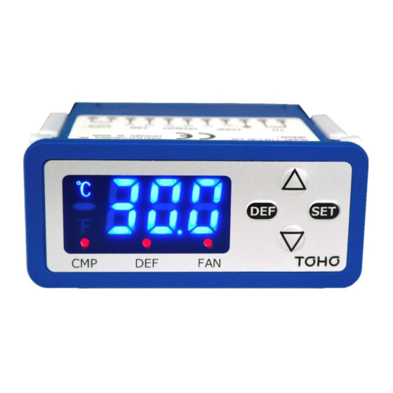
About the Display Panel
7SEG
℃
LAMP-1
LAMP-2
LAMP-3
No.
Name
Description
7SEG
7-Segment Display Section
It displays PV, characters, and setting values.
LAMP-1
COMP Output Lamp
COMP Output Monitor Lamp
LAMP-2
DEFROST Output Lamp
DEFROST Output Monitor Lamp defrost operation.
※It blinks during
LAMP-3
FAN Output Lamp
FAN Output Monitor Lamp
KEYSW-1
DEFROST Key
It switches between defrost and stop by pressing the key
for 3 seconds.
KEYSW-2
SET Key
It will be used to change program and temperature settings.
KEYSW-3
UP Key
It increases each setting value.
KEYSW-4
DOWN Key
It decreases each setting value.
Terminal Layout (back side of the product)
①
②
③
④
⑤
⑥
⑦
Thermostat
COMP
DEFROST
INPUT
OUTPUT
OUTPUT
Warning
・ Remove the back cover upon connecting wires.
・The appropriate material of copper wire for the connection of input and output is AWG16-26.
・ Length of the peeled wire: 6mm.
・ Tightening torque: 0.5–0.6N・m
・ Check if input and output terminals are properly wired.
Caution
・ Attach the back cover after the wiring.
・ Do not touch the terminal when power is ON to avoid electric shock.
Conformed Standards
・Safety : EN61010-1
・EMC : EN61326-1
List of Parameters
Screen Location
Name
Temperature Setting SV Setting
SV Limiter Max
SV Limiter Min
Sensitivity Options
Sensitivity
ST1
COMP Output
Program
Delay Time
Setting
PV Correction
Output at Sensor
Abnormality
Key Lock
COMP Output at Defrost
DEFROST Output
ST2
OFF Time
DEFROST Output
ON Time
After Defrost
COMP Output
Delay Time
DEFROST Output
Delay Time
FAN Output Function
ST3
FAN Output Delay Time
KEYSW-1
KEYSW-3
KEYSW-2
KEYSW-4
⑧
⑨
⑩ ⑪
FAN
Power
OUTPUT
INPUT
Character Setting Range Initial Value Remarks
SLL ~ SLH'
10.0
SLH'
SLL ~ 99.9
99.9
SLL'
-40.0 ~ SLL
-40.0
CMD
0/1
0
C
0.1 ~ 19.9
1.0
CDT
0 ~ 999
0
PVS'
-9.9 ~ 9.9
0.0
CEO
ON/OFF
OFF
LOC
ON/OFF
OFF
DCO
COF/CON
COF
DOF
0 ~ 48
4
DON
1 ~ 99
10
DCT
0 ~ 30
1
DDT
0 ~ 999
0
F F
F1 ~ F4
F1
FDT
0 ~ 999
30
Unit:
Second
Unit: Hour
Unit:
Minute
Unit:
Minute
Unit:
Second
Unit:
Second
Advertisement

Related Manuals for TOHO TTM-C30 Series


Summary of Contents for TOHO TTM-C30 Series
- Page 1 TTM-C30 SERIES Operation Manual Controller for Refrigerator About the Display Panel May 2017 (First Edition) 7SEG Thank you for purchasing TTM-C30. Kindly read this operation manual for proper usage. For details about specifications and usage, please contact the shop where you have purchased KEYSW-1 ℃...
- Page 2 : Continue the operation ●Key Lock ・ If LOC=ON, each setting on the program setting (other than the key lock) cannot be changed. Website http://www.toho-inc.com E-mail Address info@toho-inc.co.jp ■Main Office Sales Department 2-4-3 Nishi-Hashimoto, Midori-Ku, Sagamihara-Shi, Kanagawa-Ken 252-0131 Japan (042)700-2100 (Representative Line) FAX (042)700-2118 ●COMP Output at Defrost...
Need help?
Do you have a question about the TTM-C30 Series and is the answer not in the manual?
Questions and answers