Table of Contents
Advertisement
Quick Links
Advertisement
Table of Contents

Related Manuals for TOHO TTM-210 Series


Summary of Contents for TOHO TTM-210 Series
- Page 1 Digital Controller TTM-210 series User’s Manual TOHO ELECTRONICS INC.
- Page 2 User’s manual for digital controller TTM-210 series Introduction Thank you for purchasing Toho Electronics’ TTM-210 series. Before using the products, thoroughly read this manual for a better understanding of them. Ensure to store this manual and use it whenever needed.
- Page 3 Warnings Improper wiring to the equipment may cause a failure, such as fire. Upon completion of wiring, ensure to verify the proper wiring before turning on electricity. Do not turn on electricity until all wiring is complete. Do not touch portions of high voltages such as power supply terminals, as an electric shock may be resultant.
- Page 4 Notation convention in this manual ★ Summary notation Abbreviations in alphabetical characters are used for the diagrams and text in this manual. Some major examples are as follows. Abbreviation Term Present value Setting value Auto-tuning Determined Primary operating amount Secondary operating amount Current transformer Remote SV input ★...
-
Page 5: Table Of Contents
Contents 1. Overview Outline of TTM-210 series is described, in terms of features, model configuration (codes), names of components and functions. Thoroughly read this chapter prior to the first use. 1.1 Feature ..............................1-2 1.2 Checking the product ..........................1-3 1.3 Model table .............................. - Page 6 6.14 Program setting ............................6-77 6.15 Bank automatic switching function setting .................... 6-80 7. Appendix Product specification, errors (troubles) and parameter setting table of TTM-210 series are described. 7.1 Product specifications ..........................7-2 7.2 Accessories .............................. 7-9 7.3 Error (abnormality) display ........................7-10 7.4 Troubleshooting ............................7-11...
-
Page 7: Overview
1. Overview Features of products, confirmation of products, and model coding and the name of each component or part are described in this chapter. Feature ..............................1-2 Checking the product ..........................1-3 Model table............................. 1-3 Names of parts and components ......................1-4 Input/output function and essential functions .................. -
Page 8: Feature
1.1 Feature ★ Improved controllability due to new PID algorithm (1) Time required to stabilize after start of control has been reduced (compared to Toho’s other models). (2) Jumpless control function is supported, where post-disturbance overshoots are suppressed. (3) Selection can be made from three types of PIDs. -
Page 9: Checking The Product
1.2 Checking the product Prior to the use, check the following. ★ Checking the model The model number is printed on the box and side of the product. Check that the numbers thereon matches with the model that had been ordered. ★... -
Page 10: Names Of Parts And Components
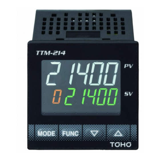
Names of parts and components ■ Front panel ★ TTM-214 * The loader port is located in the bottom wall for TTM-214. Bank display PV display TIME Unit of SV display ゚F temperature and ゚C timer display OUT1 OUT2 OUT3 OUT4 RDY COM DI1 DI2 TMR Up key Operation display Down key... - Page 11 ★ TTM-217 PV display Operation display OUT1 OUT2 OUT3 OUT4 OUT5 SV display OUT6 OUT7 Unit of TIME temperature and ゚F timer display ゚C Function key (1 to 5) Bank display Up key Down key Loader port Mode key ★ TTM-219 Bank display PV display Unit of...
- Page 12 ■ What the displays indicate ★ PV display Measurement value (present value) display, each character display and timer setting time display ★ SV display Setting value (target value) display, output operating amount display, display of setting value of each character, timer remaining time display and MVI (operating amount) display ★...
-
Page 13: Input/Output Function And Essential Functions
Output 1 CT input (2 points: optional) Outputs 2 to 7 (optional) Control section DI input (4 points: optional) Communication output (optional) TOHO communication MODBUS communication AI input (1 point: optional) Assignment of outputs Primary output Primary output Secondary output... - Page 14 ■ Input section * The following types of inputs can be selected in the input section: measurement value input (1 point), CT input (2 points), DI input (4 points) and AI input (1 point). Selectable points depend on models. See the model selection table. ★...
- Page 15 ■ Output section * The number of outputs is 7 at most, which can be assigned individually for control output, event output, RUN/RDY output, timer output and transmission output. (Assignment of outputs is to be designated at order placement.) ★ Output (OUT) 1 and output (OUT) 2 * Target connection of output can be set.
- Page 16 * For detailed specifications, see pages 6-65 and 66. ★ Loader communication * This communication function is for setting all data of TTM-210 series in a lump. * In order to use the loader communication, the dedicated software for the communication must be installed on the personal computer (PC) being used.
-
Page 17: Basic Flow Of Setting
1.6 Basic flow of setting The mode changes to either “constant value run mode” or “program run mode” when four seconds are Power-on elapsed after the power is turned-on. Initial screen * Constant run value mode is established with the SET 21 operating type setting (C/P = 0). In addition, the SET 21 and 22 parameters are not displayed. -
Page 18: Installation
2. Installation Precautions on installation, installation method and outside dimensions are described in this chapter. Precautions on installation ........................2-2 How to install or remove the equipment ....................2-3 Outside dimensions and panel cutting dimensions ................. 2-4 4D-3637-A... -
Page 19: Precautions On Installation
2.1 Precautions on installation Warning Ensure to turn the power supply off before beginning removal or reinstallation of the equipment in order to prevent an electric shock or equipment failure. ★ Ambient temperature and humidity (the equipment to be used in the specified range as listed below) (1) Temperature range: 0 to 50 °C (2) Humidity range: 20 to 85% RH (no dew condensation allowed) (3) Installation gradient: Base plane ±... -
Page 20: How To Install Or Remove The Equipment
2.2 How to install or remove the equipment ★ Installation on a panel (1) Make an opening on the panel. (2) Insert the equipment into the opening. (3) Install the mounting attachment from behind the panel. Ensure that the equipment is securely fixed. -
Page 21: Outside Dimensions And Panel Cutting Dimensions
2.3 Outside dimensions and panel cutting dimensions TTM-214 Outside dimensions Panel cutting dimensions When installing a single Packing unit of the equipment When installing n units of the equipment TTM-215 Outside dimensions Panel cutting dimensions +0.6 When installing a single 1 台... - Page 22 TTM-217 Outside dimensions Panel cutting dimensions +0 . 6 When installing a single 1 台取付時 unit of the equipment When installing n n台 取付時 units of the equipment ( 7 2× n - 3 ) Packing Loader communication terminal TTM-219 Outside dimensions Panel cutting dimensions +0.6...
-
Page 23: Wiring
3. Wiring Precautions on wiring and arrangement of terminals are described in this chapter. Precautions on wiring ........................... 3-2 Terminal arrangement ........................... 3-3 Wiring to each terminal ......................... 3-7 Examples of wiring ..........................3-15 4D-3637-A... -
Page 24: Precautions On Wiring
3.1 Precautions on wiring Warning Do not turn on the power until all wirings are complete in order to prevent an electric shock or equipment failure. For inputs from a thermocouple, use the specified wires or compensating leads. For inputs from a resistance temperature detector, use lead wires with small resistance and no resistance difference is present among the 3 wires (3-wire type). -
Page 25: Terminal Arrangement
3.2 Terminal arrangement Notation for terminal arrangement is as follows. Common Normal open +, -: There is polarity for wiring. A, B, b: There is designation for wiring. Current transformer input (no polarity) Digital input RTD: Resistance temperature detector input Thermocouple input Current input Voltage input (excluding 0 - 10 mV) - Page 26 TTM-217 Main body rear surface terminals Input power supply AI input (models in voltage and current) Relay Open collector * Outputs 3 and 4 Output 1 Output 3 are for common (C) shared Output 4 Output 2 Output 5 Other than Relay TC input RTD input...
- Page 27 Communication + 2 points of CT + Output 7 Communication + 3 points of DI CT 1 input DI 1 input CT 2 input DI 2 input Output 7 DI 3 input Open collector Relay Communication + 1 point of CT + 1 point of Communication + 1 point of CT + DI + Output 7 2 points of DI...
- Page 28 TTM-215/219 Main body rear surface terminals Input power supply CT 1 input Output 1 CT 2 input Output 2 AI input (models in voltage and current) Relay Open collector Output 5 Output 3 Output 4 Output 6 * Outputs 3 and 4 are for common (C) shared Output 7 Other than Relay...
-
Page 29: Wiring To Each Terminal
3.3 Wiring to each terminal In connection diagrams, left side of the terminal number represents inside the equipment while right side shows the external side of the equipment. Power supply TTM-214 TTM-215 Terminal Nos. ① and ② TTM-217 TTM-219 TTM-214 Type of power supply Fluctuation range Frequency... - Page 30 Input Terminal Nos. ⑩, ⑪ and ⑫ TTM-214 * Use sensors that match the types of inputs. (“K thermocouple” is set as factory default.) Terminal Nos. ㉒, ㉓ and ㉔ TTM-215 * For thermocouple input, use wires or compensated Terminal Nos. ⑭, ⑮ and ⑯ TTM-217 leads.
- Page 31 AI input (current and voltage only) Terminal Nos. ⑰ and ⑱ TTM-215 Terminal Nos. ⑨ and ⑩ TTM-217 Terminal Nos. ⑰ and ⑱ TTM-219 TTM-217 TTM-215/219 * AI input is optional. (TTM-214 is not equipped with AI input.) * Provide input signal lines distant from power supply lines, power lines or load lines so as not to affect input signal lines with noise induction.
- Page 32 Event (DI) input Terminal Nos. ⑮, ⑯, ⑰ and ⑱ TTM-214 Terminal Nos. ㉘, ㉙, ㉚, ㉛, ㉜, ㉝ and ㉞ TTM-215 Terminal Nos. ⑲, ⑳, ㉑, ㉒, ㉓ and ㉔ TTM-217 Terminal Nos. ㉘, ㉙, ㉚, ㉛, ㉜, ㉝ and ㉞ TTM-219 TTM-214 * When CT 1 or CT 2 is...
- Page 33 RS485 Loader communication * This communication function is for setting all data of TTM-210 series in a lump. * In order to use the loader communication, the dedicated software for the communication must be installed on the personal computer (PC) being used.
- Page 34 Output Terminal No. Model Output 1 Output 2 Output 3 Output 4 Output 5 Output 6 Output 7 ③ and ④ ⑤ and ⑥ ⑦ and ⑨ ⑧ and ⑨ TTM-214 ③ and ④ ⑤ and ⑥ ⑲ and ㉑ ⑳...
- Page 35 TTM-217 Output 1 Output 2 Relay SSR/current/voltage/ Relay SSR/current/voltage/ open collector open collector Outputs 3 and 4 Output 5 Relay Open collector Relay Open collector * Outputs 3 and 4 are for common shared Output 7 Relay Open collector 4D-3637-A 3-13...
- Page 36 TTM-215/219 Output 1 Output 2 Relay SSR/current/voltage/ Relay SSR/current/voltage/ open collector open collector Outputs 3 and 4 Output 5 Relay Open collector Relay Open collector * Outputs 3 and 4 are for common shared Output 6 Output 7 Relay Open collector Relay Open collector * Max.
-
Page 37: Examples Of Wiring
3-4 Examples of wiring Input: K thermocouple, output 1: relay contact output and single phase 100 V Configuration example (Example) TTM-214 Power Temperature sensor supply (K thermocouple) TIME ゚F External ゚C relay OUT1 OUT2 OUT3 OUT4 RDY COM DI1 DI2 TMR Heater Connection configuration TTM-214... - Page 38 Input: resistance temperature detector, output 1: SSR drive voltage and single phase 100 V Configuration example (Example) TTM-219 TRS1245 Temperature sensor (resistance Heater temperature detector) TIME ゚F ゚C OUT1 OUT2 OUT3 OUT4 OUT5 OUT6 OUT7 Power supply Connection configuration TTM-219 Power supply Heater...
- Page 39 Input: resistance temperature detector, output 1: SSR drive voltage and 3-phase 200 V Configuration example * Usable SSR in 3-pahse 200 V is a product with the input current of 10 mA or less. (Example) TTM-214 Temperature sensor (resistance temperature detector) Heater TIME...
- Page 40 Input: K thermocouple, output 1: SSR drive voltage, output 2: relay contact output and single phase 100 V (heating/cooling control) Configuration example (Example) TTM-215 TRS1245 Temperature sensor Heater (K thermocouple) TIME ゚F ゚C OUT1 OUT2 OUT3 OUT4 OUT5 OUT6 OUT7 Refriger- External ator...
- Page 41 Input: K thermocouple, output 1: relay contact output, output 2: transmission output and single phase 100 V Configuration example (Example) TTM-214 Power Temperature sensor supply (K thermocouple) TIME ゚F External ゚C relay OUT1 OUT2 OUT3 OUT4 RDY COM DI1 DI2 TMR Heater Recorder Connection configuration...
- Page 42 4. Basic operation Basic operation is described in this chapter. Flow of setting mode ..........................4-2 Basic operation ............................4-4 4.2.1 Switchover of parameters (flow as a whole) .................. 4-4 4.2.2 Description of setting item selection screen ................. 4-19 4.2.3 Setting of input types ........................
-
Page 43: Flow Of Setting Mode
4.1 Flow of setting mode Power-on The equipment does not operate for about 4 seconds after power-on. INP1 Initial screen At SET 21 program mode setting At SET 21 program mode setting In (C/P 0) program run mode In (C/P = 0) constant value run mode 4 seconds 4 seconds Constant value run mode screen... - Page 44 ■ Initial screen The input type number is displayed right after the power turns on, and in 4 seconds, the run mode screen is displayed. Power-on Initial screen INP1 Parameter for input display Input type No. (“0” is set at factory shipment.) 4 seconds Constant value run PV value (present value)
-
Page 45: Basic Operation
4.2 Basic operation Flow of each setting item selection screen and each setting mode is described. 4.2.1 Switchover of parameters (flow as a whole) * The ▲/▼ key is used for switching over setting item selection screens. Operating mode * The MODE key is used for switching over screens in each setting mode. The screen loops back to the setting item selection screen. - Page 46 Flow of each setting mode Constant value run mode Program run mode SET21 program mode setting SET21 program mode setting A (C/P = 0) constant value run mode is established. A (C/P = 1) program run mode is established. 1. PV/SV screen 1.
- Page 47 SET 1: Input 1 setting mode 0. Setting item selection screen MODE key 1 Input 1 type setting MODE key 2. Scaling upper limit setting * Displayed with current/voltage input. MODE key 3. Scaling lower limit setting * Displayed with current/voltage input.
- Page 48 SET 2: Input 2 setting mode SET 3: Key function setting mode 0. Setting item 0. Setting item selection screen selection screen 1. Function key 1 1. Input 2 type setting function setting 2. Scaling upper limit setting 2. Function key 2 * Displayed with function setting current/voltage input.
- Page 49 SET 4: Control setting mode 0. Setting item selection 11. Primary control screen operating amount MODE key MODE key 1. Bank setting 12. Primary control output gain setting MODE key MODE key 13. Tuning type setting 2. Bank upper limit setting MODE key MODE key...
- Page 50 32. Setting of primary 21. Anti-reset windup control loop fault time MODE key MODE key 22. Setting of primary 33. Setting of primary control operation control OFF point amount limiter upper position selection MODE key MODE key 23. Setting of primary 34.
- Page 51 42. Setting of secondary 52. Setting of secondary control operation amount control OFF point limiter upper limit position MODE key MODE key 43. Setting of secondary 53. Secondary control control operation amount safeguard off timer limiter lower limit (0 to 99 minutes) MODE key MODE key 44.
- Page 52 SET 5: OUT 1 setting mode 0. Setting item selection 10. Event polarity setting screen 1. Target connection 11. Transmission output setting function setting 2. Event function 1 12. Transmission scaling setting upper limit setting 3. Event upper limit 13. Transmission scaling setting lower limit setting To SET 05, item 0...
- Page 53 SET 6: OUT 2 setting mode 0. Setting item selection 10. Event polarity setting screen 11. Transmission output 1. Target connection function setting setting 2. Event function 1 12. Transmission scaling setting upper limit setting 3. Event upper limit 13. Transmission scaling setting lower limit setting To SET 06, item 0...
- Page 54 SET 7: OUT 3 setting mode SET 8: OUT 4 setting mode 0. Setting item selection 0. Setting item selection screen screen 1. Target connection 1. Target connection setting setting 2. Event function 1 2. Event function 1 setting setting 3.
- Page 55 SET 9: OUT 5 setting mode SET 10: OUT 6 setting mode 0. Setting item selection 0. Setting item selection screen screen 1. Target connection 1. Target connection setting setting 2. Event function 1 2. Event function 1 setting setting 3.
- Page 56 SET 11: OUT 7 setting mode SET 12: CT setting mode 0. Setting item selection 0. Setting item selection screen screen 1. Target connection 1. CT 1 target connection setting setting 2. Event function 1 2. CT 1 current value setting monitor 3.
- Page 57 SET 14: Timer 1 setting mode SET 15: Timer 2 setting mode 0. Setting item selection 0. Setting item selection screen screen 1. Function setting 1. Function setting 2. Unit setting 2. Unit setting 3. SV permissible range 3. SV permissible range setting setting 4.
- Page 58 SET 16: Timer 3 setting mode SET 17: Communication setting mode 0. Setting item selection 0. Setting item selection screen screen 1. Function setting 1. Communication protocol setting 2. Communication 2. Unit setting parameter setting 3. SV permissible range 3. Communication speed setting setting 4.
- Page 59 SET 18: Initial setting mode 0. Setting item selection 11. Blind temporary call screen setting 1. Password cancel 12. Setting value backup 2. PV normal indication setting 13. Initialization of setting value 3. PV indication auto-switching 14. Password setting : Low To SET 18, item 0 4.
-
Page 60: Description Of Setting Item Selection Screen
4.2.2 Description of setting item selection screen Setting item Description selection screen SET 01 Mode regarding input 1 setting P6-2 to 7 SET 02 Mode regarding input 2 setting P6-8 to 11 SET 03 Mode regarding key function setting P6-12 and 13 SET 04 Mode regarding control content setting P6-14 to 48... -
Page 61: Setting Of Input Types
4.2.3 Setting of input types Settings for matching the input types being used is done. * The factory default is set at “0: K thermocouple”. Power-on Parameter for input display Initial screen Input type No. (“0” is set at factory shipment.) SET 21 program mode setting A (C/P = 0) constant value run mode SET 21 program mode setting... -
Page 62: Setting Of Key Functions
4.2.4 Setting of key functions How to set key functions is described. Constant value run mode screen For program run mode screen: PV value (present value) PV value (present value) SV value (target value) SV value (PRoG) Hold MODE key pressed for 2 seconds. Hold MODE key pressed for 2 seconds Input 1 setting screen Setting mode is the same as that for constant... -
Page 63: How To Set The Sv Limiter Setting
4.2.5 How to set the SV limiter setting The SV limiter is for setting a settable range with upper and lower limits. The range is a basis for setting the proportional band for the PID control. Constant value run mode screen For program run mode screen: PV value (present value) PV value (present value) -
Page 64: How To Set Control Types
4.2.6 How to set control types How to set control types is described. Constant value run mode screen For program run mode screen: PV value (present value) PV value (present value) SV value (PRoG) SV value (target value) Hold MODE key pressed for 2 seconds Hold MODE key pressed for 2 seconds. - Page 65 Continued from the previous page S04-9 Type B mode setting screen * The type of the PID Type B mode is set in this screen. * The number displayed in the screen coincident with that listed in the Type B mode setting table. * Use the ▲/▼...
-
Page 66: How To Set Outputs
4.2.7 How to set outputs The description in this section is on how to set the OUT (output) 2 from the event output, which is set at factory shipment, to the secondary output. For program run mode screen: Constant value run mode screen PV value (present value) PV value (present value) SV value (PRoG) -
Page 67: How To Set Priority Screens
4.2.8 How to set priority screens How to set priority screens is described. Constant value run mode screen For program run mode screen: PV value (present value) PV value (present value) SV value (PRoG) SV value (target value) Hold MODE key pressed for 2 seconds. Hold MODE key pressed for 2 seconds Input 1 setting screen Setting mode is the same as that for constant... -
Page 68: Switchover To The Blind Setting Mode
4.2.9 Switchover to the blind setting mode How to set the blind function is described. Constant value run mode screen For program run mode screen: PV value (present value) PV value (present value) SV value (PRoG) SV value (target value) Hold MODE key pressed for 2 seconds Hold MODE key pressed for 10 seconds. - Page 69 Continued from the previous page Hold MODE key pressed for 3 seconds. Holding the MODE key pressed for 3 seconds in any screen above results in changing the screen. MODE key MODE key Use the ▲/▼ key to change Use the MODE key to change the item to be displayed.
-
Page 70: Switchover To The On/Off Control
4.2.10 Switchover to the ON/OFF control The ON/OFF control is set in BANK 1 for the initial setting at factory shipment. How to set the ON/OFF control is described. Constant value run mode screen For program run mode screen: PV value (present value) PV value (present value) SV value (target value) SV value (PRoG) - Page 71 5. Operating the equipment How to operate the equipment is described in this chapter. Precautions on operating the equipment ....................5-2 Operating monitor display ........................5-3 5.2.1 Operating amount monitor ......................5-3 5.2.2 Timer remaining time monitor: Run mode ..................5-3 5.2.3 Temperature measurement monitor: Run mode ................
-
Page 72: Precautions On Operating The Equipment
5.1 Precautions on operating the equipment Before beginning operation or turning on the power, check the following. ★ Operation for turning on the power The equipment is not equipped with a power switch. Connecting a power will turn the power of the unit ON. -
Page 73: Operating Monitor Display
5.2 Operating monitor display 5.2.1 Operating amount monitor: SET 04 (control setting mode) ★ Output percentage at control is displayed. 1) Primary control operating amount monitor screen S04-10 Primary control operating amount * Smaller number indicates smaller operating (output) amount; larger number indicates larger operating (output) amount. -
Page 74: How To Set Run Settings
5.3 How to set run settings The target value (SV) setting, control setting and event setting are described as examples for constant value run settings. 5.3.1 Target value (SV) setting When the target value (SV) to be set at 450 °C ①... - Page 75 ② When setting the digit shift function by assigning it on the FUNC key Power-on Initial screen SET 21 program mode setting SET 21 program mode setting A (C/P = 0) constant value A (C/P 0) program run run mode is established. mode is established.
- Page 76 Continued from the previous page Operating mode screen Measurement value (PV) Target value (SV): Set to “0” at factory shipment Target value setting screen * Pressing the FUNC key blinks on and off the numerical character located rightmost. Pressing the MODE key changes the blinking character to lighting, which indicates determination of the setting.
-
Page 77: On/Off Control Setting
5.3.2 ON/OFF control setting When a measurement value (PV) being controlled reaches the target value (SV), the control output is turned off. Then, the control output is turned on when the measurement value (PV) goes beyond the peak value, approaches the target value (SV), and goes beyond it. This move is repeated at a particular position. The adjustment sensitivity (sensitivity range), in this case, is defined as the difference between the point where the control output turns off (measurement value) and point where the control output turns on. - Page 78 Continued from the previous page 2) How to set the adjustment sensitivity In order to stabilize the equipment operation, a particular range is provided for switching on and off in the ON/OFF control. This range is called “adjustment sensitivity (hysteresis or sensitivity range).” What is described below is how to set the adjustment sensitivity after the control method is changed to the ON/OFF control in the bank setting.
-
Page 79: Pid Control Setting
5.3.3 PID control setting ★ Setting the PID control The “PID Control” is set as factory default, and the values for P = proportional band, I = integration, D = derivation and proportional cycle are provisional values. Those values are as follows: P1 = 3.0, I = 0, D = 0, proportional cycle = 1 second (SSR type) or 20 seconds (relay type). - Page 80 ② Start using the function key Set the function key function to the AT start/stop function as the first step. For constant value run mode screen: For program run mode screen: PV value (present value) PV value (present value) SV value (PRoG) SV value (target value) Hold MODE key pressed for 2 seconds.
- Page 81 2) How to start self-tuning * Self-tuning is a function to determine the PID constant when starting operation of the controller and when changing the target value. After determining the PID constant, self-tuning is not executed in the next start of operation, unless the target value is changed.
- Page 82 3) How to manually set the PID constant * The PID constant is set manually and individually in SET 04 (control setting mode). For constant value run mode screen: For program run mode screen: PV value (present value) PV value (present value) SV value (PRoG) SV value (target value) Hold MODE key pressed for 2 seconds.
-
Page 83: Heating/Cooling Pid Control Setting
5.3.4 Heating/cooling PID control setting ★ Setting the heating/cooling PID control For the heating/cooling control, the output is selected and set for the subject of control to other than the output 1, as well as the output function must be set to the secondary output, since the function is set, at factory shipment, to the event output. - Page 84 Continued from the previous page S04-12 Tuning type setting screen * Tuning types are set in this screen. * Use the ▲/▼ key for the setting. * The value is set at “1” at factory shipment. Changing “1” to “5” results in “PID auto-tuning” for both primary and secondary controls.
-
Page 85: Indicator Setting
5.3.5 Indicator setting ★ Setting as an indicator Blinding the target value (SV) enables to use the screen as an indicator. Constant value run mode screen PV value (present value) SV value (target value) Hold MODE key pressed for 10 seconds. Input 1 setting screen Each set screen Each setting mode... - Page 86 Continued from the previous page Control setting mode Each set screen Each setting mode Press MODE key six times. S04-6 Control type setting screen * Control types are set in this screen. * Use the ▲/▼ key for the setting. * The value is set at “1”...
-
Page 87: Excessive Ascent Prevention Unit (Alarm Unit) Setting
5.3.6 Excessive ascent prevention unit (alarm unit) setting ★ Setting for the excessive ascent prevention unit Setting to use the OUT 1 (output 1) as the excessive ascent prevention unit in constant value run mode Constant value run mode screen PV value (present value) SV value (target value) Hold MODE key pressed for 2 seconds. -
Page 88: Event Setting
5.3.7 Event setting ★ Setting the event setting value (alarm value) When setting OUT 2 for the event setting value (alarm value) Setting condition: Deviation lower limit, with standby function, 30 °C and sensitivity of 1 °C (no other functions) This setting is not possible in case that no selection is made for outputs as an option. - Page 89 Continued from the previous page 5. Event sensitivity setting screen * Event sensitivity is set in this screen. * Use the ▲/▼ key for the setting. * The value is set at “0” at factory shipment. Setting “0” to “1” results in setting the sensitivity range of the lower limit alarm to 1 °C. Temperature that an alarm enters: 170 °C Temperature that an alarm cancels: 169 °C * Holding the MODE key pressed for 2 seconds moves each setting screen to the run mode screen.
-
Page 90: How To Set Md/Ready
5.3.8 How to set MD/READY ★ Start of control (RUN) or stop of control (READY) is selected. Switchover of RUN/READY can be executed through the key operation with the FUNC key assigned, or through optional digital (DI) input or communication function. ①... - Page 91 ② Setting with the DI function (event input) Optional DI function (event input) is required. For constant value run mode screen: For program run mode screen: PV value (present value) PV value (present value) SV value (PRoG) SV value (target value) Hold MODE key pressed for 2 seconds.
-
Page 92: How To Set Each Function And Description Of Function
5.4 How to set each function and description of function 5.4.1 Auto-tuning (AT) function ■ What the auto-tuning is • Auto-tuning (AT) is a function to operate turning on and off a subject of control so that the PID parameter best suited for a set temperature is automatically calculated and set. •... - Page 93 Re-execution of AT PID parameters calculated by AT are not necessarily best suited for all states. Re-execute AT because best suited control may not be possible for cases listed below where settings or states are changed. Changes on other than this Changes on this equipment equipment Sensor (changed to different...
- Page 94 ■ Post-AT control characteristics per control type Note The control characteristics graph is an example and may differ depending on subjects of controls. Take care it. Post-AT control characteristics for setting of PID control types A to C Measurement value (PV) Control setting value (SV) Type A...
-
Page 95: Self-Tuning Function
5.4.2 Self-tuning function ■ What the self-tuning is • Self-tuning is defined as a function that automatically executes tuning without requiring operator to provide instructions and corrects the PID constant at the time of operation start (including power-on), change of setting value or generation of hunting. •... - Page 96 Note Precautions on the use Self-tuning is affected by the present control results, as it is a function to correct the PID constant using responses from the normal control. Under the following environments, precise compensation may not be possible. (1) Control system with large disturbances (when hunting-like operation appears due to disturbances) (2) Control system with much time required for providing control outputs Under the following cases, use auto-tuning.
-
Page 97: Mode/Manual Function
5.4.3 Mode/manual function ■ Mode (MD)/manual (MAN) function Controls set in the control mode and manual controls can be switched over using the FUNC key, DI or communication. Changeable controls are RUN, READY, MANUAL and timer controls in the control mode (MD) of SET 4. -
Page 98: Bank Function
5.4.4 Bank function ■ What the bank function is • The bank function is a function that enables a desired control to be effective through changing the bank settings for which parameters are preset in each bank and thereby no change of temperatures, PID values or alarm settings are required each time when different temperature controls or alarm settings are set on a single unit of this equipment. - Page 99 < How to set > For setting the control setting mode (SET 04) ---see the page 6-14. For setting the bank setting mode (SET 20) --- see the page 6-72. ■ Operation flow Power-on About 4 seconds (automatic) Run mode MODE key: 2 seconds Input 1 setting mode SET 01 screen...
- Page 100 From ① △/▽ key Set corresponding parameters into each bank. Control setting mode SET 04 screen MODE key Bank switchover bANK *: 0 to 7 bANK * screen MODE key Other bank setting to be made Parameter setting Bank already set Control setting mode SET 04 screen MODE key...
-
Page 101: Timer Function
5.4.5 Timer function ■ What the timer function is • A function to generate an event for a predetermined time period or predetermined time after a trigger is activated. Some major examples of the use and settings are as follows. ■... - Page 102 ■ Where the control is desired to start/stop by pressing the FUNC key (manual start) Example of setting for a control for 20 minutes at 180 °C, 2 hours after the FUNC key is pressed SEt03 Name Setting content Setting value No setting of time for the key held Function key 1 function setting pressed/timer start/reset...
- Page 103 ■ Where contact outputs are desired to be provided when a measurement value comes to a target value (SV start) Setting example for output 1 to be provided for 1 minute after 180 °C is reached SEt04 Name Setting content Setting value Control setting 180C...
- Page 104 ■ Where contact outputs 3 and 4 are desired to be provided in sequence (Event * start) Setting example where the output 3 is provided using the timer 1 and then the timer 2 starts operation to provide the output 4 when the timer 1 terminates operation SEt7/8 Name Setting content...
- Page 105 ■ Where the equipment is used as a simplified programmable controller (manual start and event * start) Setting example where temperature is raised to 100 °C in 1 minute, maintained at 100 °C for 1 minute, and then lowered to 0 °C in 1 minute SEt03 Name Setting content...
- Page 106 215/219 ⑦-⑮ ⑲-㉘ ⑬-㉑ Connect the output 3 with DI 1. ⑨-⑯ ㉑-㉙ ⑮-㉒ ⑧-⑰ ⑳-㉚ ⑭-㉓ Connect the output 4 with DI 2. ⑨-⑱ ㉑-㉜ ⑮-㉔ Note When connecting the output and DI, select an open collector for the output. FUNC key Power supply...
- Page 107 ■ Complementary explanation of “RDY lamp” lighting status The table below shows an indication status of the RDY lamp when timer operation is set for control mode. The indication status varies depending on the SET 04 control MD status (MD/READY). TIMEx Before After...
-
Page 108: Loop Abnormality Function
5.4.6 Loop abnormality function ■ What the loop abnormality is − The function is to detect an abnormality in the control loop. − When a value falls in the judgment domain with respect to the conditions of the control loop anomaly MV threshold(MS*) and control loop anomaly PV threshold(tS*), the control loop anomaly PV change threshold is judged at each “LoP*”... - Page 109 < How to set > Power-on About 4 seconds (automatic) Operating mode MODE key: 2 seconds Input 1 setting mode SET 01 screen △/▽ key Control setting mode SET 04 screen MODE key Primary control loop Set the primary control abnormality abnormality time setting time setting, using the △/▽...
-
Page 110: Current Transformer (Ct) Abnormality Function
5.4.7 Current transformer (CT) abnormality function ■ What CT (current transformer) is • CT is a function to detect that outputs are not properly turned on and off due to failure of relays or SSRs. • For detection of failure, using CT, ensure to wire the CT terminal and output terminal (such as heater power supply), set the CT * target connection setting (CI *) and CT 1 abnormality current value setting (Ct 1), and establish the control effective. - Page 111 ■ Calculation of the CT 1 abnormal current value setting Detection current to be set is calculated with the following equation as an indication: Current normal value + current at heater disconnection ∴ CT 1 abnormal current value setting value = Note Take care that the current in a multiplication factor of N flows when the load wire is wound around CT N times due to too small a measurement current.
- Page 112 ■ For 3-phase ■ Delta connection Example: Where 3 heaters of 200 V and 2 kW are used [When normal] Load Load Load To equipment CT input To equipment CT input Normal current is 17.3 A (≒√3 × 10 A) for each phase. [When disconnected in between phases] [When disconnected on load side] Disconnected...
- Page 113 ■ Star connection Example: Where 3 heaters of 200 V and 2 kW are used [When normal] Load Load To equipment CT input To equipment CT input Normal current is 5.8 A {≒10 A × (1/√3)} for each phase. [When disconnected in between phases] Disconnected Load Load...
- Page 114 ■ V connection Example: Where 2 heaters of 200 V and 2 kW are used [When normal] To equipment CT input Load Load To equipment CT input The current that flows in the target device for CT installation is 17.3 A (≒√3 × 10 A). [Disconnected on the common side] [When disconnected on load side] To equipment...
-
Page 115: Position Proportional Control
5.4.8 Position proportional control ■ What the position proportional control is • In the position proportional control, the temperature of the subject is controlled through adjusting the flow rate, which depends on the valve opening ratio. The valve opening ratio is controlled by open or close signal that is output for the valve, where an operating amount is calculated by the PID control, taking into account the valve motor stroke time. -
Page 116: Concurrent Temperature Ascent Function
Oven • How to use the function 1) Set the communication protocol setting (SEt 17) to TOHO protocol. 2) Set the communication switchover setting (SEt 17) to a concurrent temperature ascent master for a channel that requires the longest time to reach the target value, and to concurrent temperature ascent slaves for others. -
Page 117: Explanation Of The Program Run Function
5.5 Explanation of the program run function ■ The digital controller TTM-210 Series can provide a simple program controller. This chapter explains the program run of TTM-210 Series. • A program run of this product is established by automatically controlling “bank function” and “program step function.”... -
Page 118: Operation Flow Of The Program Run
5.5.1 Operation flow of the program run ■ Digital controller: This section explains operation process of the program run using TTM-210. To perform a program run, the SET 20, SET 21 and SET 22 parameters must be set. ■ The setting content is as follows: Set a parameter desired to change with setting value in the SET 20 bank setting for each step. -
Page 119: Set 21 Program Function Setting
5.5.2 SET 21 program function setting ■ The SET 21 program function setting is for setting operating method of a program run. Set the setting values for the following: “program run mode,” “power failure compensation range,” “time unit,” “WAIT range” and “Program run start/stop.” The flowchart below is for “SET 21 program function setting.”... - Page 120 *1: Operating type setting (C/P) Set “operating method.” Setting range Initial value: 0 in constant value run mode 0: Constant value run mode (program run mode OFF) 1: Program run mode (program run mode ON) *2: Program rum mode setting (PGMd) Set “return operating method”...
- Page 121 *4: Time unit setting (H/MP) Set “time unit” and “step transfer condition (time countdown condition)” of a step. Setting range Initial value: 0: Step time (hour: minute) 0: Step time (hour: minute) 1: Soak time 1 (hour: minute) 2: Soak time 2 (hour: minute) 3: Step time (minute: second) 4: Soak time 1 (minute: second) 5: Soak time 2 (minute: second)
-
Page 122: Set 21 Program Function Setting Screen
5.5.3 SET 21 program function setting screen ■ The program function setting screen is shown below. PV value (present value) SV value (setting value) Hold MODE key pressed for 2 seconds Input 1 setting screen SET01 INP1 Press the key or key several times. Program function setting mode SET21 Press MODE key. -
Page 123: Set 22 Program Setting
5.5.4 SET 22 program setting ■ Set a pattern (program) of the program run in the SET 22 program setting. [Setting items] • Set “number-of-use-steps” of the program. • Set “bank designation,” “step SV value” and “step time” of each step. •... - Page 124 *5: Bank setting (St*bK) Switchover is made for each step of a program. “Bank No.” can be designated. Setting range: St*bK = 0 to 7 (The range depends on SET 4 bANKH.) Initial value: St* bK = 0 (* = 1 to 8) The symbol “*”...
-
Page 125: Set 22 Program Setting Screen
5.5.5 SET 22 program setting screen ■ The program setting screen is shown below. PV value (present value) SV value (setting value) Hold MODE key pressed for 2 seconds Input 1 setting screen SET01 INP1 Press the key several times or key once. Program setting mode SET22 * When C/P = 0, the setting SET 22 is not displayed. -
Page 126: Explanation Of The Screen Display And Operation Of A Program Run
5.5.6 Explanation of the screen display and operation of a program run ■ Switching the run screen Switching between “constant value run,” in PV display which no program is used, and “program run,” in TTM-214 section which a program automatically executes a run, is performed with “SET 21 C/P.”... - Page 127 ■ Regarding operation and display of a program run The diagram below shows “screen display during a program run.” The screens are categorized into “before run,” “run in process” and “run end” depending on run status. Before run Run in process Run end Program run screen Blinks...
- Page 128 ■ Regarding the “program run mode” operation list table “Program run” is categorized into “before run,” “run in process” and “run end” depending on run status, for which the operable keys vary. “Operation list table” indicates key operations corresponding to the status.
- Page 129 < Operation list table (2/3) > Key operation INDEX Screen Behavior Run status Type Operation method ⑤ Step time Before run MODE Prolonged press of 2 seconds To the setting mode monitor MODE Depression To the program run start/stop screen FU1-5 Depression Follows the function key setting.
- Page 130 < Operation list table (3/3) > Key operation INDEX Screen Behavior Run status Type Operation method ⑪ Timer 1 Before run MODE Prolonged press of 2 seconds To the setting mode monitor Run end MODE Depression To the timer 2 monitor screen FU1-5 Depression Follows the function key setting.
- Page 131 5.5.7 Complementary explanation of the program run ■ Regarding the time unit setting (H/MP) Parameters for “step time” and “countdown condition” are provided in the program settings. “Countdown condition” can be selected with a setting value. The example below is for STEPn = 5 (step number 5).
- Page 132 If an increase rate of PV is larger than that of SV, the countdown begins after SV reaches SV3. Wait range Step time Soak time 1 Soak time 2 ① ② ③ < Countdown condition > Step time (H/MP = 0 or 3): The program steps proceed in accordance with the time set for each step. Time countdown begins regardless of the statuses of PV and SV values and a step proceeds to the next one upon set time elapsed.
- Page 133 ■ Regarding the ramp function The ramp function can be used even during a program run. To use the function, first set a RMP for either one of the banks [SET 20 bNK01 to 16]. Next, set the RMP value for each bank. The function is executed with the RMP value designated by [SET 22 St*bK] during the program setting.
- Page 134 ■ Regarding the time signal output function A signal of time signal can be output for each step during a program run. Timers 1 to 3 for step time are usable as is, as a timer independent from those is used for the signal. Note The function is active only during a run.
- Page 135 This section introduces the timer function. Timer behavior is determined by defining the following parameters: timer function setting [tMF 1 to tMF 3], unit setting [H/M 1 to H/M 3], SV start allowable range setting [tSV 1 to tSV 3], On delay timer [oNt 1 to oNt 3], Off delay timer [oFt 1 to oFt 3], repetition count setting [RUN 1 to RUN 3], etc.
- Page 136 Set the ON delay timer, OFF delay timer and repeat count for a timer. Set the ON delay timer for Timers 1 to 3 using [oNt 1 to oNt 3]. Set the OFF delay timer for Timers 1 to 3 using [oFt 1 to oFt 3]. Set the repetition count for Timers 1 to 3 using [RUN 1 to RUN 3].
- Page 137 ■ Regarding repetitive run A repetitive run of a designated step can be executed during a program run. Any step (as a whole or part) of program steps set in SET 22 can be repeated. The diagram below shows an example of using this function where the steps 2 and 3 of total 4 steps are repeated 3 times.
- Page 138 ■ Regarding switchover of the input types If input 1 type [INP 1] is set in a bank, an operation of switching the input type can be executed during a program run by using the “step* designated bank setting [St*bK] ” function. Note Note that the input type must be selected from the same group as listed below.
- Page 139 ■ The diagram below shows an example of a program run with StEPN = 8. Operation Operation In the process In Program Operation Operation STOP Operation Suspended Suspended of ending Operation Start Operation Start Operation Stop Program Operation Manipulation Display Indication Manipulation 0031 0020...
-
Page 140: Explanation Of The Bank Automatic Switching Function
5.6 Explanation of the bank automatic switching function ■ Regarding the bank automatic switching function The bank function can be automatically switched for each temperature. Setting control parameters for each temperature beforehand enables realization of optimization and an accurate control. As parameters unrelated to control can also be set similarly to the case of the normal bank function, application for each temperature is possible for such functions as the timer and event functions. -
Page 141: Bank Automatic Switching Setting
5.6.1 Bank automatic switching setting ■ The operation procedure of bank automatic switching is explained below. Switching conditions are set in the SET 23 parameter. The bank switching method (input, switching sensitivity, etc.) and switching threshold are set. Parameters desiring to be switched are set for each threshold in the SET 20 bank setting. For details of the bank setting method, see Section 5.4.4 Bank function (P5-28 to 30). - Page 142 *1: Bank automatic switching function selection (bAF) Set the bank automatic switching ON/OFF. Setting range Initial value: 0 Bank automatic switching run OFF 0: Bank automatic switching run OFF 1: Bank automatic switching run ON *2: Bank automatic switching source setting (bAS) Select an input source.
-
Page 143: Set 23 Bank Automatic Switching Function Setting Mode Setting Screen
5.6.2 SET 23 bank automatic switching function setting mode setting screen ■ The bank automatic switching function setting screen is shown below: PV value (present value) SV value (setting value) Hold MODE key pressed for 2 seconds Input 1 setting screen SET01 INP1 Press the ... -
Page 144: Complementary Explanation Of The Bank Automatic Switching Function
5.6.3 Complementary explanation of the bank automatic switching function Regarding the zone threshold* setting [PM1 to PM7]: If all seven points at most are set with different values one another, eight zones can be established for each temperature allowing eight banks to be used. The setting range is from SLL to SLH. If all seven points are set to SLH, the threshold is integrated into one zone to provide the maximum value (applicable only for the bank 0). - Page 145 ■ Setting example of the bank automatic switching function setting mode (2 banks used) The example shows a threshold for auto switching to be of one point. In this case, Bank 0 and Bank 1 are used. When two banks are used (zone threshold: 1 point): Bank Bank...
- Page 146 ■ Setting example 3: Bank automatic switching function setting mode (when the program run function is also used) This example shows use of both the program run and eight banks for the bank automatic switching function. The “designated bank” setting for a program run is ineffective in a bank automatic switching function run.
- Page 147 ■ Regarding the “bank function” priority If multiple settings are set for the bank switching designation, bank switching is applied from of a function with a higher priority. The following applies (“1” is of the highest priority). 1. “Bank automatic switching function” SET 23 [PM*] zone threshold* setting (“*”: Zone No.) 2.
- Page 148 ■ Regarding switchover of the input types If input 1 type [INP 1] is set in a bank, an operation of switching the input type can be executed during a program run by using the bank automatic switching function. Note Note that the input type must be selected from the same group as listed below.
- Page 149 6. Explanation on parameters Settings of various types of parameters are described in this chapter. Input 1 type setting ................................... 6-2 Remote SV input type setting ..............................6-8 Function key function setting..............................6-12 Control function setting ................................. 6-14 Output (from OUT 1 to OUT 7) type setting ........................6-49 Current transformer (CT) setting ............................
-
Page 150: Input 1 Type Setting
Input 1 type setting ■ Input 1 type setting SEt01 Setting content Initial value INP1 Press the MODE key for making a setting effective (including reverse feed). INP1 0 to 20 See the input 1 type setting table. Set the input type of the input 1. The input 1 is for a multi-input for thermocouple, resistance temperature detector, voltage and current. - Page 151 Input 1 connection table Model TTM-210 Series Model No. Connection Wiring Terminal No. Terminal No. Terminal No. − − Note Switchover of the input types may result in change of each setting value due to limits being applied, such as SLH, SLL, tRH and tRL.
- Page 152 ■ PV compensation gain/PV compensation zero setting SEt01 Setting content Initial value INP1 PV CORRECTION FUNCTION SETTING PVF1 0 : PV Gain / Zero Point Correction 1 : PV X・Y 2-Point Correction PV Correction Gain Setting PVG1 1.000 0.500 to 2.000 (X) PV Correction Zero Setting Thermocouple -999.9 to 999.9 (C)
- Page 153 PV compensation zero setting: PV (measurement value) for the input 1 is added by the compensation value. Setting example: Where PV of the equipment is displayed for 90°C and the actual temperature is 100°C, and the display is to be compensated to 100°C, using the PV compensation zero setting.
- Page 154 PV X-Y 2-POINT CORRECTION SETTING Determine any two points within the input range (upper and lower limit), then convert to corrected value to the PV of Input 1. For Example) When the PV of the product is; 90°C indication but actual temp. is 100°C 310°C indication but the actual temp.
- Page 155 ■ PV filter setting SEt01 Setting content Initial value INP1 PdF1 0.0 to 99.9 (seconds) The PV filter setting is a function that demonstrates the CR filter effect on software through performing a first-order lag calculation for PV of the input 1. The filter effect is set using the time constant [t].
-
Page 156: Remote Sv Input Type Setting
• Display of the upper limit side: Up to + 12 % of the full scale Full scale is defined as the range from FSL 2 to FSH 2. Remote SV input connection table Model TTM-210 Series Model No. Connection Wiring Terminal No. - Page 157 PV 100.0%(FSH2) 0.0%(FSL2) Remote SV input 20mA Note (1) Display resolution is 20,000 or less. Take care it when the range from FSL 2 to FSH 2 is set larger than 20,000. Setting example: Fluctuation or missing value of PV may be caused when the remote SV input is set to the input type of 4 - 20 mA, FSL 2 to -19999 digits and FSH 21 to 29999 digits.
- Page 158 PV compensation zero setting: PV (measurement value) for the remote SV input is added by the compensation value. Setting example: Where PV of the equipment is displayed for 90°C and the actual temperature is 100°C, and the display is to be compensated to 100°C, using the PV compensation zero setting. The display after PV compensation is 100°C = 90°C (before PV compensation) + 10°C.
- Page 159 ■ PV filter setting SEt02 Setting content Initial value INP2 PdF2 0.0 to 99.9 (seconds) The PV filter setting is a function that demonstrates the CR filter effect on software through performing a first-order lag calculation for PV of the remote SV input. The filter effect is set using the time constant [t].
-
Page 160: Function Key Function Setting
6.3 Function key function setting ■ Function settings for function keys 1 to 5 SEt03 Setting content Initial value Press the MODE key for making a setting effective. Function settings No function Digit shift Follow the Set21 C/P Operation Type Setting Constant Operation Mode Control Mode (MD) / Control Stop (RdY) Program Mode... - Page 161 (6) ENT The FUNC key is used as a setting recording key. Take care that a move to the next parameter without recording results in a return of the setting to the one before the change. Note For moving to another function from the ENT function, select the desired function and press the FUNC (ENT) key. (7) Bank switchover The FUNC key is used as a key for switching over the banks 0 to 7.
-
Page 162: Control Function Setting
6.4 Control function setting ■ Bank switchover/Bank Upper Limit Setting SEt04 Setting content Initial value bANK 0 to 7 Bank 0 to 7 bANKH Bank Upper Limit Setting 0 to 7 Switching over to the banks 0 to 7 is executed. Switchover to either one of the banks 0 to 7 results in that a parameter set in the memory bank is switched over to a setting value for each bank. - Page 163 ■ Control mode SEt04 Setting content Initial value Control start Manual Control stop tIME1 Timer 1 operation tIME2 Timer 2 operation tIME3 Timer 3 operation Set the control mode. Control stop (RdY): Primary/secondary operating amount limiter lower limit is output. Control start (RUN): Normal control is executed.
- Page 164 ■ Forward/reverse operation setting SEt04 Setting content Initial value Reverse operation Forward operation Set the forward/reverse operation of the primary control. <Reverse operation> • Reverse operation (heating control) is a control where the operating amount increases as PV (measurement value) lower than SV (setting value).
- Page 165 ■ Primary control operating amount SEt04 Setting content Initial value MLL 1 to MLH 1 (%) The screen is for displaying the operating amount for the primary control. The operating amount cannot be set for the normal control. The operating amount can be set only when the control mode is set to manual. ■...
- Page 166 ■ Tuning type setting SEt04 Setting content Initial value Primary auto-tuning (for primary PID/position proportional) Primary self-tuning (for primary PID/position proportional) Secondary auto-tuning (for primary PID/secondary PID) Secondary self-tuning (for primary PID/secondary PID) Primary/secondary auto-tuning (for primary PID/secondary PID) Set the auto-tuning or self-tuning of the primary/secondary control. Note (1) This setting is allowed only when either primary or secondary control is set for the PID control or position proportional control.
- Page 167 ■ AT start screen SEt04 Setting content Initial value Use the / key for start and stop. PV/SV is displayed during AT. The screen is used for starting AT. Pressing the key or key allows start/stop of AT. After setting the AT start/stop in the key function setting, pressing the FUNC key allows the AT start/stop.
- Page 168 ■ Integral time setting SEt04 Setting content Initial value 0 to 3600 (seconds) Set the integral time. Setting of 0 second results in no integral operation. Both heating and cooling sides share to use this setting in the heating cooling control. (Individual setting is not allowed.) The integral operation is an operation that makes the deviation between the setting value and measurement value, which is generated in the proportional control, approach 0.
- Page 169 ■ Primary control proportional cycle SEt04 Setting content Initial value 20.0 0.1 to 120.0 (seconds) (1.0) ( ) When OUTPUT1 is SSR drive. Set the primary control proportional cycle. Relay contact output, voltage output for SSR drive or open collector output has only the state of ON or OFF for output, and thereby no proportional operation is offered.
- Page 170 ■ Primary control operating amount limiter upper limit SEt04 Setting content Initial value Digital output MLL 1 to 100.0 (%) MLH1 100.0 Analog output MLL 1 to 110.0 (%) Set the primary control operating amount limiter upper limit. A limit is set for the upper limit of the operating amount calculated. Output 100% Operating amount...
- Page 171 ■ Primary control operating amount change limiter ascent setting SEt04 Setting content Initial value 0.0 to 549.9 (%) Function turned off at 0.0 (%) setting Set the primary control operating amount change limiter ascent. A limit is set to the ascent percentage of the operating amount change calculated. An operating amount allowed with ascent for a second is set in the unit of percentage.
- Page 172 ■ Primary control soft-start output setting SEt04 Setting content Initial value ML 1 to MH 1 (%) 100.0 Set the primary control soft-start output setting. A limit is set in a particular time period (or the primary control soft-start time) on the operating amount calculated. ■...
- Page 173 ■ Primary control abnormality operating amount setting SEt04 Setting content Initial value Digital output 0.0 to 100.0 (%) FAL1 Analog output -10.0 to 110.0 (%) Set the primary control at-abnormality operating amount setting. This operating amount is the one provided in case of failure of gauges and such. <Conditions on the primary control at-abnormality operating amount>...
- Page 174 ■ Primary control loop anomaly PV threshold SEt04 Setting content Initial value Thermocouple/resistance temperature detector input 0.0 to 999.9 ( C)0 to 999 ( C) Voltage/current input 0 to 9999 (digit) Set the primary control loop anomaly PV threshold . The function is to detect an abnormality in the control loop.
- Page 175 ■ Primary control loop anomaly MV threshold SEt04 Setting content Initial value MV threshold 100.0 MLL1 to MLH1 Set the primary control loop anomaly MV threshold. The function is to detect an abnormality in the control loop. When MV is more than the threshold, a judgment of the loop anomaly acts. The real judgment in PS1 and LoP1.
- Page 176 ■ Primary control loop anomaly PV change threshold SEt04 Setting content Initial value Thermocouple/resistance temperature detector input 0.0 to 999.9 ( C)0 to 999 ( C) Applicable only for time judgment when PS 1 = 0 (LoP1) Voltage/current input 0 to 9999 (digit) Applicable only for time judgment when PS 1 = 0 (LoP1) Set the primary control loop anomaly PV change threshold.
- Page 177 ■ Primary control loop abnormality time setting SEt04 Setting content Initial value LoP1 0 to 9999 (seconds) Set the primary control loop abnormality time setting. The function is to detect an abnormality in the control loop. - The control loop anomaly PV change threshold is judged at each “LoP1” time. A loop abnormality is determined if each change threshold is judged to be equal to or below “PS1.”...
- Page 178 ■ Primary control off-point position selection setting SEt04 Setting content Initial value SV unit setting Upper CMod Middle Lower Set the primary control off-point position selection. Set the selection setting to “0” for allowing to set the off-point position of sensitivity in the SV setting unit of °C and such. Set the selection setting to “1”...
- Page 179 <Forward operation> C2 CP2 CP1 C1 Cmod = 0 (SV) -db C1: Sensitivity setting 1 ON C2: Sensitivity setting 2 CP1: Off-point setting 1 = positive value CP2: Off-point setting 2 = negative value db: Dead band = positive value OFF...
- Page 180 ■ Primary control sensitivity setting SEt04 Setting content Initial value Thermocouple/resistance temperature detector input 0.0 to 999.9 (C) 0 to 999 (C) Voltage/current input 0 to 9999 (digit) Set the primary control sensitivity. Sensitivity (hysteresis) of ON/OFF operation is set. For heating control, the sensitivity is set below SV. ■...
- Page 181 < dIR=1 When primary control is Forward operation > C1 Off-point CP1 = 0 ON C1: Sensitivity setting OFF △ PV SV High CP1 C1 Off-point CP1 = positive value ON C1: Sensitivity setting CP1: Off-point position OFF C point: SV + CP1 △...
- Page 182 ■ Secondary control operating amount SEt04 Setting content Initial value MLL 2 to MLH 2 (%) The screen is for displaying the operating amount for the secondary control. The operating amount cannot be set for the normal control. The operating amount can be set only when the control mode is set to manual. ■...
- Page 183 ■ Secondary control proportional cycle SEt04 Setting content Initial value 0.1 to 120.0 (seconds) 20.0 Set the secondary control proportional cycle. Relay contact output, voltage output for SSR drive or open collector output has only the state of ON or OFF for output, and thereby no proportional operation is offered.
- Page 184 ■ Secondary control operating amount limiter upper limit SEt04 Setting content Initial value Digital output MLL 2 to 100.0 (%) MLH2 100.0 Analog output MLL 2 to 110.0 (%) Set the secondary control operating amount limiter upper limit. A limit is set for the upper limit of the operating amount calculated. Output 100% Operating amount...
- Page 185 ■ Secondary control operating amount change limiter ascent setting SEt04 Setting content Initial value 0.0 to 549.9 (%) Function turned off at 0.0 (%) setting Set the secondary control operating amount change limiter ascent. A limit is set to the ascent percentage of the operating amount change calculated. An operating amount allowed with ascent for a second is set in the unit of percentage.
- Page 186 ■ Secondary control abnormality operating amount setting SEt04 Setting content Initial value Digital output 0.0 to 100.0 (%) FAL2 Analog output -10.0 to 110.0 (%) Set the secondary control at-abnormality operating amount setting. This operating amount is the one provided in case of failure of gauges and such. <Conditions on the secondary control at-abnormality operating amount>...
- Page 187 ■ Secondary control loop anomaly PV threshold SEt04 Setting content Initial value Thermocouple/resistance temperature detector input 0.0 to 999.9 ( C)0 to 999 ( C) Voltage/current input 0 to 9999 (digit) Set the secondary control loop anomaly PV threshold . The function is to detect an abnormality in the control loop.
- Page 188 ■ Secondary control loop anomaly MV threshold SEt04 Setting content Initial value MV threshold 100.0 MLL2 to MLH2 Set the secondary control loop anomaly MV threshold. The function is to detect an abnormality in the control loop. When MV is more than the threshold, a judgment of the loop anomaly acts. The real judgment in PS2 and LoP2.
- Page 189 ■ Secondary control loop anomaly PV change threshold SEt04 Setting content Initial value Thermocouple/resistance temperature detector input 0.0 to 999.9 ( C)0 to 999 ( C) Applicable only for time judgment when PS 2 = 0 (LoP2) Voltage/current input 0 to 9999 (digit) Applicable only for time judgment when PS 2 = 0 (LoP2) Set the secondary control loop anomaly PV change threshold.
- Page 190 ■ Secondary control loop abnormality time setting SEt04 Setting content Initial value LoP2 0 to 9999 (seconds) Set the secondary control loop abnormality time setting. The function is to detect an abnormality in the control loop. - The control loop anomaly PV change threshold is judged at each “LoP2” time. A loop abnormality is determined if each change threshold is judged to be equal to or below “PS2.”...
- Page 191 ■ Secondary control sensitivity setting SEt04 Setting content Initial value Thermocouple/resistance temperature detector input 0.0 to 999.9 (C) 0 to 999 (C) Voltage/current input 0 to 9999 (digit) Set the secondary control sensitivity. Sensitivity (hysteresis) of ON/OFF operation is set. For heating control, the sensitivity is set in the upper side of SV. ■...
- Page 192 < dIR=1 When secondary control is Reverse operation > C2 Off-point CP2 = 0 ON C2: Sensitivity setting OFF △ PV SV High C2 Off-point CP2 = positive value CP2 ON C2: Sensitivity setting CP2: Off-point position A point: SV + CP2 OFF...
- Page 193 ■ Manual reset SEt04 Setting content Initial value 0.0 to 100.0 (%), when CNt is 1, 2 or 6 -100.0 to 100.0 (%), when CNt is 3 or 4 Set the manual reset. The operating amount is added by the value of the manual reset. This value is to be set for canceling the off-set that is generated in the proportional control.
- Page 194 ■ Ramp time setting SEt04 Setting content Initial value Thermocouple/resistance temperature detector input 0.0 to 999.9 (C/minute) Voltage/current input 0 to 9999 (digit/minute) Set the ramp time. A change of SV per minute is set when SV is changed. The ramp control starts from the present PV. <Start condition>...
- Page 195 ■ Valve motor stroke time SEt04 Setting content Initial value 0.1 to 999.9 (seconds) Set the valve motor stroke time. Output is generated for the time set for VLt (valve motor stroke time) when PV (measurement value) changes in range by the amount identical to the proportional band range.
- Page 196 ■ Valve motor drive dead band SEt04 Setting content Initial value 0.0 to 100.0 (%) Set a range such that the position proportional output is not provided even when the operating amount changes. The range is represented as a ratio to the proportional band range. When the proportional band is 200°C and Vdb (valve motor drive dead band) is set to 10.0 %, the actual range is 20°C.
-
Page 197: Output (From Out 1 To Out 7) Type Setting
6.5 Output (from OUT 1 to OUT 7) type setting ■ Outputs 1 to 7 target connection setting SEt05 oUt1 Setting content Initial value SEt11 oUt7 Primary output Secondary output Event output RUN output RDY output Timer 1 output Timer 1 during-on-delay output o1F: 0 Timer 1 during-off-delay output Timer 1 during-[on + off]-delay output... - Page 198 ■ Event function 1/upper and lower limits/sensitivity/delay timer settings SEt05 oUt1 Setting content Initial value SEt11 oUt7 Function None Deviation upper and lower limits Deviation upper limit Deviation lower limit Deviation range Absolute value upper and lower limits Absolute value upper limit Absolute value lower limit Absolute value range Add-on function...
- Page 199 ■ Event function 1 operation The operation range (range for turn-on) of the event function 1 assigned for outputs 1 to 7 is set in terms of the event function 1 setting, and event upper limit, event lower limit and event sensitivity settings. See below for the event function 1 operation range.
- Page 200 1) State when no event has occurred No event occurs when RUN/READY is switched over. 2) Standby state No event occurs when RUN/READY is switched over. 3) State when an event has occurred (an event occurs when the event moves out from the standby state.) By switching over from RUN to READY, the event turns to OFF.
- Page 201 ■ Event function 3 setting (CT abnormality) SEt05 oUt1 Setting content Initial value SEt11 oUt7 Function None CT 1 abnormality CT 2 abnormality CT 1 abnormality + CT 2 abnormality Add-on function E1F3 None Hold E7F3 Delay Hold + delay Control mode interlocking function All modes RUN/MAN mode only...
- Page 202 ■ Event function 4 (loop abnormality) SEt05 oUt1 Setting content Initial value SEt11 oUt7 Function Nonexistent E1F4 Existent Add-on function E7F4 None Hold Set the event function 4 (loop abnormality). Event function 4 is a function that detects output abnormalities, and that outputs signals from the event output. This function can be used when the event function 4 is set and the target connections of the outputs 1 to 7 are set to event outputs.
- Page 203 ■ Output 1 and 2 transmission output function setting SEt05 oUt1 Setting content Initial value SEt06 oUt2 Transmission content selection PV (measurement value) output SV (setting value) output MV 1 (primary control operating amount) output tRN1 tRN1=01 MV 2 (secondary control operating amount) output tRN2 tRN2=01 Control SV (Setting Value) output...
- Page 204 ■ Output 1 and 2 transmission scaling upper limit/lower limit setting SEt05 oUt1 Setting content Initial value SEt06 oUt2 Thermocouple/resistance temperature detector input tRL* to 2999.9 (C) 1200 tRH1 tRL* to 2999 (C) tRH2 Voltage/current input 12000 tRL* to 29999 (digit) Thermocouple/resistance temperature detector input -1999.9 to tRH* (C) tRL1...
-
Page 205: Current Transformer (Ct) Setting
6.6 Current transformer (CT) setting ■ CT 1 target connection setting SEt12 Setting content Initial value Connected to OUT 1 (settable when DO) Connected to OUT 2 (settable when DO) Connected to OUT 3 (settable when an option existent) Connected to OUT 4 (settable when an option existent) Connected to OUT 5 (settable when an option existent) Connected to OUT 6 (settable when an option existent) Connected to OUT 7 (settable when an option existent) - Page 206 ■ CT 2 target connection setting SEt12 Setting content Initial value Connected to OUT 1 (settable when DO) Connected to OUT 2 (settable when DO) Connected to OUT 3 (settable when an option existent) Connected to OUT 4 (settable when an option existent) Connected to OUT 5 (settable when an option existent) Connected to OUT 6 (settable when an option existent) Connected to OUT 7 (settable when an option existent)
-
Page 207: Di Setting
6.7 DI setting ■ DI function setting SEt13 Setting content Initial value Press the MODE key for making a setting effective (including reverse feed). **** |||| |||+-- DI 1 setting (settable when an option existent) ||+--- DI 2 setting (settable when an option existent) |+---- DI 3 setting (settable when an option existent) +----- DI 4 setting (settable when an option existent) Active... - Page 208 6: Start and Stop of the timer operation, which is set in “function setting - DI 1 to 4 start” for timers 1 to 3 (see SET 14 to 16 on page 6-59, are switched over. Stopping the timer during operation results to midway termination (state of control stop or event output OFF). Note Setting with DI supersedes the setting change of “communication”...
- Page 209 When “AT start” is assigned to DI 1 (close active) Setting example: Set dIF to 0005 and dIP to 0000. When DI is inactive When DI is active 200 200 At 200 DI1 Switch OFF Switch ON Lighting Usable DIs for each product model DIs indicated in the table are usable when DI types are optionally designated.
-
Page 210: Timer Function Setting
6.8 Timer function setting ■ Timer function setting SEt14 tIME1 Setting content Initial value SEt16 tIME3 Auto start Manual start SV start DI 1 start (settable when an option existent) DI 2 start (settable when an option existent) DI 3 start (settable when an option existent) DI 4 start (settable when an option existent) tMF1 Event 1 start... - Page 211 ■ Start SV permissible range setting SEt14 tIME1 Setting content Initial value SEt16 tIME3 Thermocouple/resistance temperature detector input 0.0 to 999.9 (C) tSV1 0 to 999 (C) tSV3 Voltage/current input 0 to 9999 (digit) When the SV start is set, it is set that at what temperature range (°C) the timer should start. The permissible range is determined in the range of tSV with SV in the center as shown below.
- Page 212 ■ Remaining time monitor SEt14 tIME1 Setting content Initial value SEt16 tIME3 tIA1 0:00 to 99:59 (hour: minute or minute: second) 0:00 Start/stop of timer using / key tIA3 Remaining time of timers 1 to 3 is displayed. Timers can be started on this screen. When the ON delay timer and OFF delay timer are set, the setting value for the ON delay timer is displayed.
-
Page 213: Communication Function Setting
Press the MODE key for making a setting effective (including reverse feed). TOHO protocol MODBUS protocol (RTU mode) MODBUS protocol (ASCII mode) Set the communication protocol (communication procedure). For details of communication, see “TTM-210 series operation manual - communications.” ■ Communication parameter setting SEt17 Setting content Initial value... - Page 214 1 to 247 (stations) Set the address for communication. Take care that no identical numbers are assigned for more than one unit of equipment. For details of communication, see “TTM-210 series operation manual - communications.” ■ Response delay time setting SEt17...
-
Page 215: Initial Setting
6.10 Initial setting ■ Password input SEt18 Setting content Initial value INIt PASS 0000 to 9999 0000 (Blinking) Change the 4-digit number and press the MODE key for canceling. To move to the initial setting mode, set the password. A password is set for the product, key in the number in this screen, using the / key. Then, press the MODE key. In the initial setting mode, the FUNC key is assigned for the digit shift function. - Page 216 ■ PV indication auto-switching : Switching range SEt18 Setting content Initial value INIt Thermocouple/resistance temperature detector input 0.0 to 999.9 (C) 0 to 999 (C) Voltage/current input 0 to 9999 (digit) PV indication auto-switching : switching range SV PV indication auto-switching : switching range PV...
- Page 217 ■ Indication setting at CT abnormality SEt18 Setting content Initial value INIt Lighting E3dSP Flashing (fast) Flashing (slow) Set the indication for CT abnormality. ■ Indication setting at Loop abnormality SEt18 Setting content Initial value INIt Lighting E4dSP Flashing (fast) Flashing (slow) Set the indication for Loop abnormality.
- Page 218 In the initial setting, the FUNC key is assigned for the digit shift function. Note Do not forget the password. Note In case of password forgotten, contact TOHO’s sales department. For contacting TOHO’s sales department, see the last page of this user’s manual. 4D-3637-A 6-70...
-
Page 219: Priority Screen Setting
6.11 Priority screen setting ■ Priority screens 1 to 16 setting SEt19 Setting content Initial value PRI01 PRI02 PRI03 PRI04 PRI05 PRI06 PRI07 PRI08 Parameters for SEt 01 to SEt 17 PRI09 PRI10 PRI11 PRI12 PRI13 PRI14 PRI15 PRI16 Set parameters frequently used or desired to display in the priority screen. This enables a quick setting or display of the corresponding screen only by a press of the MODE key in the operating mode. -
Page 220: Bank Function Setting
6.12 Bank function setting ■ Banks 1 to 16 setting SEt20 Setting content Initial value bNK01 bNK02 bNK03 bNK04 bNK05 bNK06 bNK07 bNK08 Parameters for SEt 01 to SEt 17 bNK09 bNK10 bNK11 bNK12 bNK13 bNK14 bNK15 bNK16 Max. 16 of any parameter setting value can be changed in the banks 0 to 7. For the no use of the bank, set the setting to “OFF.”... -
Page 221: Program Function Setting
6.13 PROGRAM FUNCTION SETTING ■ Operation Type Setting Set21 Setting Contents Initial Value Operation Type Setting Constant Operation Mode Program Mode *1 Operation Type Setting (C/P) The program operation will take place when the Program Mode is set. The Program Mode executes the program operation by automatically switching the “Bank Function” and “Program Step Function”. - Page 222 ■ Program Mode Setting / Power Failure Compensation Range Setting SEt21 Setting Contents Initial Value Program Mode Setting Program 1(w/o Power Failure Compensation) Program 2(w/o Power Failure Compensation) PGMd Program 1(w/ Power Failure Compensation) Program 2(w/ Power Failure Compensation) *Program 1:After the operation, control stops. *Program 2: After the operation, the control continues.
- Page 223 ■ Time Setting Set21 Setting Contents Initial Value Time Setting Step Time (Hr./Min.) Soak Time 1(Hr./Min.) Soak Time 2 (Hr./Min.) Step Time (Min./Sec.) Soak Time 1 (Min./Sec.) H/MP Soak Time 2 (Min./Sec.) Step Time:After a lapse of set time, it will proceed to the next step.
- Page 224 ■ Wait Range Setting Set21 Setting Contents Initial Value Wait Range Setting During Temperature Input 0 to 999(0.0 to 999.9) ( ) Soak Time 1 ( ) 0 to 999(0.0 to 999.9) Soak Time 2 During H/MP(Soak Time 2) 、the behavior will be identical to that of (Soak Time 1) with Setting=0 During Analog Input (digit)...
-
Page 225: Program Setting
6.14 PROGRAM SETTING ■Setting No. of Steps to be Used / Step SV* Setting / Step Time* Setting INITIAL SETTING CONTENTS VALUE Setting of no. of steps used n=1 to 8 Setting Value Range Step* Designated Bank Setting St*BK=0 to 7 Setting Value Range *=1 to (StEPN Setting Value) Step SV*... - Page 226 ■Setting No. of Steps to be Used / Step SV* Setting / Step Time* Setting Behavior Diagram Operation Operation In the process In Program Operation Operation STOP Operation Suspended Suspended of ending Operation Start Operation Start Operation Stop Program Operation Manipulation Display Indication Manipulation...
- Page 227 ■Repeat Start Step Setting / Repeat End Step Setting / Setting the Times of Execution / Setting the no. of Execution / No. of Times Monitor Initial Setting Contents Value Repeat Start Step Setting 1 to Repeat End Step Setting Setting Value Range (ENdSt) Repeat End Step Setting...
-
Page 228: Bank Automatic Switching Function Setting
6.15 BANK AUTOMATIC SWITCHING FUNCTION SETTING ■Bank Automatic Switching Function Selection Initial Setting Contents Value Bank Automatic Switching Function Selection Bank Auto-Switching Operation OFF Bank Auto-Switching Operation ON ※In case the “Bank Auto-Switching Operation ON” is set; ・The Bank Switching Setting with the FUNC Key will be invalid. - Page 229 ■Bank Automatic Switching Source Setting Initial Setting Contents Value Bank Automatic Switching Source Setting Function *0 Select SV value *1 Select ramp SV value *2 Select PV value Control Mode Interlock Function 0* All Mode 1* RUN/MAN Mode Only 2* RUN Mode Only ※Select the source for the SV value to which the Bank Automatic Switching will be done.
- Page 230 ■Zone Threshold* Setting Initial Setting Contents Value Zone Threshold* Setting Setting Range SV Limiter Lower Limit (SLL) to SV Limiter Upper Limit (SLH) <PM* <= PM*+1> (PM*) will depend on the setting value of bANKH PM7 PM6 to SLH PM6 PM5 to SLH 1200 PM5 PM4 to SLH PM4 PM3 to SLH...
- Page 231 ■Zone Threshold Switching Sensitivity Range Setting Initial Setting Contents Value Zone Threshold Switching Sensitivity Range Setting During Temperature Input 0 to 999(0.0 to 999.9) (℃) During Analog Input 0 to 9999 (digit) ※Sets the sensitivity setting for the threshold of the bank auto-switching.
-
Page 232: Appendix
7. Appendix Product specifications and accessories are described in this chapter. Product specifications ..........................7-2 7.1.1 Rating and performance ......................... 7-2 7.1.2 Environmental conditions ......................7-7 Accessories ............................. 7-9 7.2.1 Current transformer ........................7-9 7.2.2 Loader cable ........................... 7-9 Error (abnormality) display ........................7-10 7.3.1 Display on measurement value (PV) side .................. -
Page 233: Product Specifications
7.1 Product specifications 7.1.1 Rating and performance Input section No. of input points One point for TTM-214, and up to 2 points for TTM-215, 217 or 219 * The second point on TTM-215, 217 or 219 cannot be selected for thermocouple, resistance temperature detector or voltage 0 - 10 mV. - Page 234 0 - 10 VDC Measurement accuracy In standard environment conditions (23 ± 10 °C), ± 0.3 % ± 1 digit of FS Input resistance 1 M or larger III) When disconnected “_____” (underscale) displayed Control output: Operating amount limiter lower limit 0 - 10 mVDC Measurement accuracy In standard environment conditions (23 ±...
- Page 235 (2) Control output section No. of output points 2 points Output type (fixed per model designation) ① Relay contact output Contact type 1a contact Contact capacity 250 VAC, 3A (resistance loads) Min. loads 5 VDC, 100 mA Mechanical life 5 million counts or more Electric life 100 thousand counts or more (More than 80 thousand counts at the UL approval)
- Page 236 (3) Auxiliary output section No. of output points (see the table below) 2 points (TTM-214) Common shared 4 points (TTM-217) For TTM-217, outputs 3 and 4 are for common shared and outputs 5 and 7 are for common independent. When DI 3 exists, 4 points for 217.
- Page 237 (6) Communication Communication is in the use exclusively from loader communication. Communication specification RS-485 (1:31) Communication terminal RS-485 dedicated terminal Protocol TOHO 100-model protocol/MODBUS (RTU)/MODBUS (ASCII) Information direction Half-duplex Synchronization system Asynchronous Transmission code ASCII Interface RS-485 (2-wire) Communication speed...
-
Page 238: Environmental Conditions
TTM-214 (9 pcs) TTM-217 (12 pcs) TTM-215 and 219 (14 pcs) Output 1 monitor Output 2 monitor Output 3 monitor Output 4 monitor Output 5 monitor ... - Page 239 (5) Power consumption 100 - 240 VAC: 10 VA or less (TTM-214) 100 - 240 VAC: 11 VA or less (other than TTM-214) 24 VAC/DC: 5 W or less (TTM-214) 24 VAC/DC: 6 W or less (other than TTM-214) (6) Warm-up time 30 minutes (7) Momentary power outage No effect of power outage in a single cycle.
-
Page 240: Accessories
7.2 Accessories 7.2.1 Current transformer ★ Current transformer is used to measure current values of a heater through connecting it to TOHO’s digital controller TTM-210 series and the heater. Model: CTL-6-P-H-(S) Product specifications Current applicable 0.1 - 80.0 A rms (50/60 Hz) * This is specification for CT main frame. -
Page 241: Error (Abnormality) Display
7.3 Error (abnormality) display Content of error is displayed when an abnormality is generated on this product. 7.3.1 Display on measurement value (PV) side Display Content Handling Operation at error * When input exceeds the * Make the input fall within the * At-abnormality operating display range upper limit display range. -
Page 242: Troubleshooting
7.4 Troubleshooting Check corresponding items listed below to abnormal operation of this product before requesting for a repair. In case of no normal operation restored, contact TOHO’s sales department to return the product for a repair. Symptom Description Check item... - Page 243 Symptom Description Check item Control unstable (1) ON/OFF control is selected. (1) Change the control type from ON/OFF control * Overshoot At factory shipment, the setting is PID control. to PID control (self-tuning/auto-tuning) in the * Undershoot ON/OFF control is set in the bank 1. setting mode of SET 4, item 6.
-
Page 244: Setting List
7.5 Setting list 7.5.1 Run mode Setting Setting data Character Setting (monitor) value Initial value Unit Blind value C Present value (PV) Sensor input designation range C Target value (SV) SV limiter upper limit 1200 SV limiter lower limit 01:00 on delay Timer 1 monitor 01:00 ... -
Page 245: Input 1 Setting Mode (Set 01)
7.5.2 Input 1 setting mode (SET 01) Setting Setting data Character Setting (monitor) value Initial value Unit Blind value 0: K thermocouple 1: J thermocouple 2: T thermocouple 3: E thermocouple 4: R thermocouple 5: S thermocouple 6: B thermocouple 7: N thermocouple 8: U thermocouple 9: L thermocouple... -
Page 246: Input 2 Setting Mode (Set 02)
7.5.3 Input 2 setting mode (SET 02) Setting Setting data Character Setting (monitor) value Initial value Unit Blind value 16: 0 - 1 VDC 17: 0 - 5 VDC Input type INP2 18: 1 - 5 VDC None 19: 0 - 10 VDC 20: 4 - 20 mADC FSL 2 to SV setting range upper Scaling upper limit... -
Page 247: Control Setting Mode (Set 04) (1/4)
7.5.5 Control setting mode (SET 04) (1/4) Setting Setting data Character Setting (monitor) value Initial value Unit Blind value 0: Bank 0 1: Bank 1 2: Bank 2 3: Bank 3 Bank switchover bANK None 4: Bank 4 5: Bank 5 6: Bank 6 7: Bank 7 Bank upper limit... - Page 248 7.5.5 Control setting mode (SET 04) (2/4) Setting Setting data Character Setting (monitor) value Initial value Unit Blind value 0: Type A (normal PID) 1: Type B (overshoot PID control type suppression) None 2: Type C (disturbance suppression) Type B mode 0: Moderate (overshoot 1: Intermediate...
- Page 249 7.5.5 Control setting mode (SET 04) (3/4) Setting Setting data Character Setting (monitor) value Initial value Unit Blind value Primary control operating amount 0.0 to 549.9 change limiter ascent Primary control operating amount 0.0 to 549.9 change limiter descent Primary control MLL1 to MLH1 100.0 soft-start output...
- Page 250 7.5.5 Control setting mode (SET 04) (4/4) Setting Setting data Character Setting (monitor) value Initial value Unit Blind value Secondary control Digital output: 0.0 to 100.0 at-abnormality FAL2 Analog output: -10.0 to 110.0 operating amount C Secondary control Temperature: 0.0 to 999.9 loop anomaly PV 0 to 999 threshold...
-
Page 251: Out 3 To 7 Setting Modes (Set 07, 08, 09, 10 And 11) (1/2)
7.5.6 OUT 1 and 2 setting modes (SET 05 and 06) (1/3) Setting Setting data Character Setting (monitor) value Initial value Unit Blind value 0: Primary output 1: Secondary output 2: Event output 3: RUN output 4: RDY output 5: Timer 1 output 6: Timer 1 during-on-delay output 7: Timer 1 during-off-delay output 8: Timer 1 during-[on + off]-delay... - Page 252 7.5.6 OUT 1 and 2 setting modes (SET 05 and 06) (2/3) Setting Setting data Character Setting (monitor) value Initial value Unit Blind value Temperature: -1999.9 to 2999.9 -19999 to 2999 C Note that, for thermocouples R, S Event lower limit and B, the value of WRe 5-26 or PR 40-20 is -1999 to 9999.
- Page 253 7.5.6 OUT 1 and 2 setting modes (SET 05 and 06) (3/3) Setting Setting data Character Setting (monitor) value Initial value Unit Blind value Transmission content *1: PV (Measurement value) *2: SV (Setting value) *3: MV 1 (Primary control operating amount) Transmission output tRN1 *4: MV 2 (Secondary control...
- Page 254 7.5.7 OUT 3 to 7 setting modes (SET 07, 08, 09, 10 and 11) (1/2) Setting Setting data Character Setting (monitor) value Initial value Unit Blind value 0: Primary output 1: Secondary output 2: Event output 3: RUN output 4: RDY output 5: Timer 1 output 6: Timer 1 during-on-delay output 7: Timer 1 during-off-delay output...
- Page 255 7.5.7 OUT 3 to 7 setting modes (SET 07, 08, 09, 10 and 11) (2/2) Setting Setting data Character Setting (monitor) value Initial value Unit Blind value Temperature: -1999.9 to 2999.9 -1999 to 2999 C Note that, for thermocouples R, S Event lower limit and B, the value of WRe 5-26 or PR 40-20 is -1999 to 9999.
- Page 256 7.5.8 CT setting mode (SET 12) Setting Setting data Character Setting (monitor) value Initial value Unit Blind value 1: Connected to OUT 1 2: Connected to OUT 2 3: Connected to OUT 3 CT 1 target 4: Connected to OUT 4 None connection 5: Connected to OUT 5...
-
Page 257: Di Setting Mode (Set 13)
7.5.9 DI setting mode (SET 13) Setting Setting data Character Setting (monitor) value Initial value Unit Blind value ※, ★, ☆ and ◎ ◎: DI 1 setting ☆: DI 2 setting DI function 0000 None ★: DI 3 setting ※: DI 4 setting DI content (function) assignment table Active None... - Page 258 7.5.10 Timer 1 to 3 setting modes (SET 14, 15 and 16) Setting Setting data Character Setting (monitor) value Initial value Unit Blind value 1: Auto-start 2: Manual start 3: SV start 4: DI 1 start 5: DI 2 start 6: DI 3 start 7: DI 4 start tMF1...
- Page 259 Response delay time in 0 to 250 communication 0: Write inhibit 1: Writable Communication 2: Concurrent temperature ascent switchover master 3: Concurrent temperature ascent slave *2: “Modbus (RTU)” should not be set. *3: Only TOHO protocol can be set. 4D-3637-A 7-28...
-
Page 260: Initial Setting Mode (Set 18)
7.5.12 Initial setting mode (SET 18) Setting Setting data Character Setting (monitor) value Initial value Unit Blind value 0000 to 9999 Password cancel PASS Change the 4-digit value and press the 0000 None screen (Blinking) MODE key for release. PV normal indication NdSP 0: Lighting setting... - Page 261 7.5.14 Bank setting mode (SET 20) Setting Setting data Character Setting (monitor) value Initial value Unit Blind value Bank selection 01 bNK01 Bank selection 02 bNK02 Bank selection 03 bNK03 Bank selection 04 bNK04 Bank selection 05 bNK05 Bank selection 06 bNK06 Bank selection 07 bNK07...
-
Page 262: Program Function Setting Mode (Set 21)
7.5.15 Program function setting mode (SET 21) Setting Setting data Character Setting (monitor) value Initial value Unit Blind value Operating type 0: Constant value run mode None setting 1: Program run mode 0: Program mode 1 (without power failure compensation) 1: Program mode 2 (without power failure compensation) 2: Program mode 1 (with power... -
Page 263: Program Setting Mode (Set 22)
7.5.16 Program setting mode (SET 22) Setting Setting data Character Setting (monitor) value Initial value Unit Blind value Number-of-use-step Setting value range StEPN None setting n = 1 to 8 Setting value range Step designation St*bK St*BK = 0 to 7 None bank setting “*”... -
Page 264: Bank Automatic Switching Function Setting Mode (Set 23)
7.5.17 Bank automatic switching function setting mode (SET 23) Setting Setting data Character Setting (monitor) value Initial value Unit Blind value 0: Bank automatic switching run 1: Bank automatic switching run * With “Bank automatic switching run ON” setting: Bank automatic - Bank switching setting by using switching function the FUNC key is ineffective.
Need help?
Do you have a question about the TTM-210 Series and is the answer not in the manual?
Questions and answers