
Subscribe to Our Youtube Channel
Related Manuals for Digital Projection HIGHlite Series


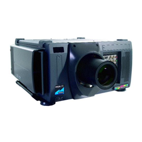
Summary of Contents for Digital Projection HIGHlite Series
- Page 1 The HIGHlite display range of SUPER-HIGH-BRIGHTNESS DIGITAL VIDEO PROJECTORS HIGHlite 5000GV USER MANUAL Revision A - 01/02/2000...
- Page 3 LBV00063; Revision A - 01/02/2000 Declaration of Conformity Directives covered by this Declaration 89/336/EEC Electromagnetic Compatibility Directive, amended by 92/31/EEC & 93/68/EEC. 73/23/EEC Low Voltage Equipment Directive, amended by 93/68/EEC. Products covered by this Directive Large Screen Projector type HIGHlite 5000GV. Basis on which Conformity is being declared The products identified above comply with the protection requirements of the above EU directives, and the manufacturer has applied the following standards:-...
- Page 4 Supplier’s Declaration of Conformity Declaration of Conformity with Electromagnetic Compatibility Standards as required under the Radiocommunications Act. We, Digital Projection Limited of Greenside Way, Middleton, Manchester, UK, M24 1XX declare under our sole responsibility that the product: DLP projector model - HIGHlite 5000GV...
- Page 5 LBV00063; Revision A - 01/02/2000 Revision Record From time to time revisions will be issued to this manual. To maintain a correct and up to date copy of the manual it is important that the instructions given in revision notices are carried out. The person carrying out the revision should complete the table below.
- Page 6 LBV00063; Revision A - 01/02/2000...
- Page 7 Disclaimer Digital Projection makes a sincere effort to ensure accuracy and quality of it's published materials; however, no warranty, expressed or implied, is provided. Digital Projection disclaims any direct or indirect damages...
- Page 8 Introduction LBV00063; Revision A - 01/02/2000 Digital Projection Limited, Greenside Way, Middleton, Manchester M24 1XX, UK. Registered in England No. 2207264, Registered Office: As Above Tel: +44 (0) 161 947 3300 Fax:+44 (0) 161 684 7674 E-Mail:enquiries@digitalprojection.co.uk, service@digitalprojection.co.uk Web Site:www.digitalprojection.co.uk Digital Projection Inc.
- Page 9 Introduction LBV00063; Revision A - 01/02/2000 Outline of Contents Section A: Overview Packaging ..............A—1 Safety Advice ............. A—2 Initial Preparation ............A—5 Components ............... A—7 Section B: System Installation Installation Guidelines ..........B—1 Installation ..............B—7 Setting Up the Projector ..........B—11 Connecting Signal Sources ........
- Page 10 Introduction LBV00063; Revision A - 01/02/2000 Section D: Advanced User Information (Cont.) Technical Specification ..........D—7 Section E: Maintenance Lamp Replacement ............ E—1 Cleaning ..............E—2 Appendix Glossary ................i...
-
Page 11: Table Of Contents
Overview LBV00063; Revision A - 01/02/2000 Section A: Overview Packaging ................ A—1 Projector Packaging............ A—1 Lens Packaging............A—1 Safety Advice ..............A—2 Fire and Shock Precautions......... A—2 Lamp Precautions ............A—2 Power Supply ............. A—3 Installation Advice ............. A—4 Initial Preparation ............A—5 Pre-Installation Check .......... - Page 12 Overview LBV00063; Revision A - 01/02/2000...
- Page 13 The following components should be contained within the projector packaging. Should any of the components be absent, please contact the dealer who supplied the projector, or Digital Projection Limited (Digital Projection Inc. if in North America) immediately. 1 x HIGHlite 5000GV Projector...
-
Page 14: Fire And Shock Precautions
The projector has a warning system that displays the following message when you reach 1500 hours of operation - Lamp Running Time is Over 1500 Hours!!. When you see this message please contact your Digital Projection dealer for a replacement lamp. -
Page 15: Power Supply
Overview LBV00063; Revision A - 01/02/2000 gas, and will not cause harm if kept out of your eyes. If your eyes have been exposed to this gas, please flush your eyes out with water immediately and seek immediate medical attention. Do not rub your eyes as this could cause serious injury. -
Page 16: Installation Advice
Overview LBV00063; Revision A - 01/02/2000 Installation Advice The projector should be placed on a flat, level surface and in a dry area free from dust and moisture. Do not place the projector in direct sunlight, near heaters or heat radiating appliances. -
Page 17: Initial Preparation
0verview LBV00063; Revision A - 01/02/2000 Initial Preparation Pre-Installation Check Before mounting the projector in its intended location, the following pre-installation routine must be performed: 1. Install the AC Power Lead 2. Install the projector lens. 2. Ensure all the air flow inlet and outlet ducts are clear from obstruction. 3. -
Page 18: Remote Control Unit - Battery Installation
Overview LBV00063; Revision A - 01/02/2000 Remote Control Unit - Battery Installation The remote control unit can either be hard wired to the projector or powered by 2 AAA (HP16/RO3/LR03) alkaline batteries. The battery compartment is located on the back of the remote control. To remove the compartment cover press and open as shown below. -
Page 19: Components
0verview LBV00063; Revision A - 01/02/2000 Components Part Names Stacking Pad Digital Input Terminal Panel Remote Sensor PC Card Slot Carrying Handle Lens (optional) Ventilation (Out) Input Terminal Panel Release Lever Ventilation (In) Foot Power Switch AC Input Ventilation (In) Controls Ventilation (In) Ventilation (In) -
Page 20: Control Panel
Overview LBV00063; Revision A - 01/02/2000 Control Panel The control panel at the rear of the projector provides all the main controls necessary to operate the projector. Remote Sensor LENS SHIFT FOCUS ZOOM MENU SELECT ENTER INDICATOR POWER ON/OFF STATUS CANCEL 1 - Power Button Press to turn the projector on when the projector is in the standby condition (Main... - Page 21 Overview LBV00063; Revision A - 01/02/2000 5 - Enter Button Executes your menu selection and activates items selected from the menu. When the slidebar or dialog box is displayed: Pressing this button confirms adjustments/ setting and returns to the previous menu display. 6 - Cancel Button Press this button to exit the menu.
-
Page 22: Terminal Panel
Overview LBV00063; Revision A - 01/02/2000 Terminal Panel The Terminal Panel located at the front of the projector provides all the required connections for video, computer and remote control. INPUT3 INPUT1 INPUT2 INPUT4 R/Cr R/Cr OPTION B/Cb B/Cb H/HV H/HV REMOTE1 REMOTE2 S-VIDEO1... - Page 23 Overview LBV00063; Revision A - 01/02/2000 connection should be attached to the external equipment such as PC. The OUT connection provides for daisy-chaining multiple projectors and operating them with the same external equipment. To daisy-chain projectors, connect the IN terminal of the second projector to the OUT connection of the first projector.
-
Page 24: Rgb Digital Connectors & Optional Sdi Board
Overview LBV00063; Revision A - 01/02/2000 8 - INPUT 6 (VIDEO 2) RCA composite video connection for external equipment such as a VCR or laser disk player. 9 - INPUT 7 (S-VIDEO 1) BNC S-Video connection for use with external equipment such as a VCR or laser disk player that have separate Y and C video outputs. - Page 25 Overview LBV00063; Revision A - 01/02/2000 11 - INPUT 9 (RGB (Digital)) MDR 20 pin connectors for double or triple stacking. Use the supplied DFP cable to connect the OUTPUT terminal of the first projector to the second projector's INPUT until all the projectors are connected.
-
Page 26: Remote Control
Overview LBV00063; Revision A - 01/02/2000 Remote Control All the functions of the HIGHlite 5000GV can be controlled using the remote control. The remote control can operate either by infra red or by a direct connection to the projector via a hard wire connection. When using infra red operation the remote control has an effective range of about 7m (23 feet) and at an angle of 30°... - Page 27 System Installation LBV00063; Revision A - 01/02/2000 Section B: System Installation Installation Guidelines ............B — Screen Requirements ........... B — Positioning the Projector ..........B — Installation ............... B—7 Attaching the Power Cable Stopper ......B—7 Lens Installation ............B—8 Setting Up the Projector ..........
-
Page 28: Section B: System Installation
System Installation LBV00063; Revision A - 01/02/2000... -
Page 29: Installation Guidelines
System Installation LBV00063; Revision A - 01/02/2000 Installation Guidelines This installation section explains how to install the projector for optimum results. To do this, it is necessary to determine the following: 1. The type of screen and whether front or rear projection is to be used. 2. - Page 30 System Installation LBV00063; Revision A - 01/02/2000 Screen Width Screen Height (feet/inches) Needed to Display Full Image with Aspect Ratio: (feet) 4 x 3 5 x 4 8 x 5 14 x 9 16 x 9 8' 0" 6' 0" 6' 5"...
- Page 31 System Installation LBV00063; Revision A - 01/02/2000 30° 1.2m (4 Ft) SCREEN 60° VIEWING AREA AISLE AISLE AISLE B—3...
-
Page 32: Positioning The Projector
System Installation LBV00063; Revision A - 01/02/2000 Positioning the Projector Correct positioning of the projector is essential to achieve the best results. Before deciding on the final location of the projector please ensure you read the following information very carefully. The projector must be situated in a clean, dry environment and away from direct sunlight or heat. - Page 33 System Installation LBV00063; Revision A - 01/02/2000 500" 400" 300" 200" 100" 80" When using a zoom lens, exact positioning of the projector is not required as the image size can be adjusted. However, the projector must be located within the Throw Distance range imposed by the minimum and maximum lens throw ratios.
- Page 34 System Installation LBV00063; Revision A - 01/02/2000 The lens can be shifted within the shaded area as shown overleaf using the normal projection position as a starting point. Screen Size 0.23H 0.3H 80” 1.6 (5.25) 1.2 (3.94) 100” 2.0 (6.56) 1.5 (4.92) 0.5V 150”...
-
Page 35: Installation
System Installation LBV00063; Revision A - 01/02/2000 Installation Attaching the Power Cable Stopper The Power Cable Stopper is provided with the projector so that the cable cannot be accidentally unplugged from the AC IN. 1. Remove the two screws from under the AC IN and place to side - these screws will be required later. -
Page 36: Lens Installation
System Installation LBV00063; Revision A - 01/02/2000 Lens Installation There are three zoom lenses available for the HIGHLite 5000GV projector Model numbers TL-1Z, TL-2Z and the TL-4Z. These lenses have throw ratios of 1.5-2.5:1, 2.5-4.0:1 and 4.0-7.0:1 respectively. In addition to the zoom lenses a fixed lens is available with a throw ratio of 0.84:1. - Page 37 System Installation LBV00063; Revision A - 01/02/2000 5. Remove the cap from the rear of the lens and insert the lens so that the three pins on the lens unit are properly lined up with the holes on the projector. Do not remove the front lens cap during lens installation.
- Page 38 System Installation LBV00063; Revision A - 01/02/2000 9. Insert the lower lens hood into the retaining hook and secure. 10. Re-attach the upper lens hood while pushing the left and right bottom. 11. Secure the upper lens hood with two screws through the top of the hood. 12.
-
Page 39: Setting Up The Projector
System Installation LBV00063; Revision A - 01/02/2000 Setting Up the Projector This section describes how to select a computer or video source, adjust the picture and sound, edit a signal and adjust all other settings and adjustments for correct projector set-up. Before you turn on the projector ensure that the computer or video source is turned on and that the projector lens cap is removed. -
Page 40: Reflecting The Displayed Image
If the image is inverted when projecting an image from the rear, it can be corrected using the Orientation feature under Setup in the Projector Options Sub-menu. For further details contact your dealer or Digital Projection. Shutter Mechanism The HIGHlite 5000GV projector is equipped with a ‘Shutter’... -
Page 41: Connecting Signal Sources
System Installation LBV00063; Revision A - 01/02/2000 Connecting Signal Sources CONNECTING A VIDEO RECORDER OR LASER DISC PLAYER Video recorders and laser disc player connect to the HIGHlite 5000GV Projector using common RCA cables (not provided). To make these connections, simply: 1. - Page 42 System Installation LBV00063; Revision A - 01/02/2000 CONNECTING A DOCUMENT CAMERA To connect the HIGHlite 5000GV Projector to a document camera simply: 1. Turn off the power to your projector and document camera. 2. Using a standard video cable, connect your document camera to the Video input (or INPUT3, RGB) on your projector.
- Page 43 System Operation LBV00063; Revision A - 01/02/2000 Section C: System Operation Remote Control Overview ..........C—1 Direct Key Combinations ........... C—6 Menu System Overview ........... C—7 Navigating the Menu System ........C—9 Menu Operation ............. C—10 Main Menu ............... C—10 Source Select ..............
- Page 44 System Operation LBV00063; Revision A - 01/02/2000 Image Options (Cont.) Video Mode .............. C—22 Signal Level .............. C—24 Projector Options ............C—25 Timer ................. C—25 Menu ................ C—27 Setup ................. C—29...
-
Page 45: Section C: System Operation
System Operation LBV00063; Revision A - 01/02/2000 Remote Control Overview All the functions of the HIGHLite 5000GV projector can be controlled by the remote control unit. The remote control can be directly connected to the projector via a control cable or to provide more flexibility send infra red signals which are detected by sensors located at the front and rear of the projector. - Page 46 System Operation LBV00063; Revision A - 01/02/2000 1 - POWER ON Press to turn on the projector. The POWER indicator lights up green. 2 - POWER OFF Press and hold this button for a minimum of two seconds to turn off the projector. 3 - MENU Press to display the main menu.
- Page 47 System Operation LBV00063; Revision A - 01/02/2000 9 - INPUT The alpha-numeric INPUT buttons are used to select an input, to name a signal, or to enter a passcode during input registration. 1--INPUT 1 for RGBHV/Y, Cb/Pb, Cr/Pr 2--INPUT 2 for RGBHV/Y, Cb/Pb, Cr/Pr 3--INPUT 3 for RGB 4--INPUT 4 for Y, Cb/Pb, Cr/Pr 5--INPUT 5 for VIDEO 1...
- Page 48 System Operation LBV00063; Revision A - 01/02/2000 15 - PIXEL Displays the Pixel Adjust screen to allow adjustment of the pixel clock and phase. 16 - AUTO Adjusts the Horizontal/Vertical Position and Pixel Clock/Phase for an optimum picture. 17 - POSITION Pressing this button once will display the Blanking screen, pressing it again will display the Position screen.
- Page 49 System Operation LBV00063; Revision A - 01/02/2000 23 - ENTRY LIST (B) Display the Entry List screen. 24 - FOCUS (+/-) While pressing and holding CTL, pressing this button allows you to adjust the lens focus. 25 - MAGNIFY/ZOOM (+/-) Magnifies the size of the targeted portion of the displayed image.
-
Page 50: Direct Key Combinations
System Operation LBV00063; Revision A - 01/02/2000 Direct Key Combinations The CTL button can be used in conjunction with other remote control buttons to provide alternative functions. A list of these combinations is provided below. KEY COMBINATION ACTION CTL + INPUT (1-10) Switches to selected signal found in the Entry List. -
Page 51: Menu System Overview
System Operation LBV00063; Revision A - 01/02/2000 Menu System Overview Menu windows or dialog box typically have the following elements: Title Bar Solid Triangle OK Button Highlight Check Box Cancel Button Radio Button Slide Bar A description of all the menu system elements is provided overleaf. C—7... - Page 52 System Operation LBV00063; Revision A - 01/02/2000 Title bar - Indicates the menu title. Highlight - Indicates the selected menu or item. Solid triangle - Indicates further choices are available. A highlighted triangle indicates the item is active. Tab - Indicates a group of features in a dialog box. Selecting any tab brings its page to the front.
-
Page 53: Navigating The Menu System
System Operation LBV00063; Revision A - 01/02/2000 Navigating the Menu System Press the MENU button on the remote control to display the Main Menu. Next, use the up and down cursor buttons on the remote control to select the required sub menu and press ENTER. -
Page 54: Main Menu
System Operation LBV00063; Revision A - 01/02/2000 Main Menu The Main Menu can be accessed by pressing MENU on either the remote control or the control panel and provides access to sub-menus which allow you to control the projector and to view any system settings. Selection of sub menu options is made using the cursor keys and ENTER. -
Page 55: Source Select
System Operation LBV00063; Revision A - 01/02/2000 Source Select Source Select enables you to select an input source connected to the projector. To select an input source use the up/down buttons on your remote control or the projector cabinet to highlight the desired input type and press Enter. Available options include: RGB1, RGB2, RGB3, Component (YCbCr), Video1, Video2, S-Video1, S-Video2, RGB Digital or SDI. -
Page 56: Entry List
System Operation LBV00063; Revision A - 01/02/2000 Entry List The Entry List window contains a list of all current and previously connected input signals. ENTRY EDIT COMMAND The names and positions of the signals stored in the entry list can be modified using the Entry Edit Command. - Page 57 System Operation LBV00063; Revision A - 01/02/2000 The source name and input terminals can be modified by selecting ‘Source Name’ and ‘Input Terminal’. The appropriate Edit window will be displayed allowing you to make adjustments. This option is only available for sources which are not currently being displayed.
-
Page 58: Adjustments
System Operation LBV00063; Revision A - 01/02/2000 Adjustments The Adjustments Menu provides access to the image controls. Use the up and down cursor buttons on your remote control or the projector cabinet to highlight the menu item you want to adjust. Picture The Picture Menu provides access to the Brightness, Contrast, Colour, Hue. -
Page 59: Blanking
System Operation LBV00063; Revision A - 01/02/2000 Brightness - Adjusts the brightness level or the back raster intensity. Contrast - Adjusts the intensity of the image according to the incoming signal. Color - Increases or decreases the color saturation level (not available for RGB). Hue - Varies the color level from +/- green to +/-blue. -
Page 60: Image
System Operation LBV00063; Revision A - 01/02/2000 Image The Image Menu provides access to the Auto Adjust, Position, Pixel Adjust, Resolution and Video Filter features of the projector. AUTO ADJUST When Auto Adjust is turned On, the projector automatically determines the best resolution for the current RGB input signal and adjusts the Horizontal Position, Vertical Position and Pixel Adjust settings to give an optimum image. - Page 61 System Operation LBV00063; Revision A - 01/02/2000 Clock - Used to fine tune the computer image or to remove any vertical banding that might appear. Phase - Adjusts the clock phase or used to reduce video noise, dot interference or cross talk.
-
Page 62: Color Temperature
System Operation LBV00063; Revision A - 01/02/2000 VIDEO FILTER This feature reduces video noise. Video filtering is controlled by a slide bar with adjustments made using the cursor buttons on the remote control. When the bar is set at 0, video filtering is Off. High filtering is applied when the bar is set to 1/3rd. When the bar is at 2/3rds, medium filtering is applied and when set to full, low filtering is applied. -
Page 63: Switcher
System Operation LBV00063; Revision A - 01/02/2000 Switcher This feature is only available when used with ISS-6020. R/G/B GAIN This feature adjusts the red, green and blue input levels of the signal. VOLUME This feature adjusts the volume of the audio output. Adjust the sound corresponding to the appropriate slot. -
Page 64: Lamp
System Operation LBV00063; Revision A - 01/02/2000 Lamp LAMP MODE Lamp Mode allows the lamp power supply to operate under the following settings: Auto - This setting keeps the projector's original light output level for a certain peri- od of time. High-Bright - This setting consumes maximum current from the AC input and results in the most light output. -
Page 65: Image Options
System Operation LBV00063; Revision A - 01/02/2000 Image Options The Image Options menu provides optional controls such as gamma correction, component signal selection, wide screen and video noise reduction features. Image Mode The Image Mode menu allows you to adjust the Aspect Ratio, VD Delay and Clamp Timing ASPECT RATIO This feature allows you to define the correct proportions for displayed image. -
Page 66: Video Mode
System Operation LBV00063; Revision A - 01/02/2000 CLAMP TIMING This function sets the standard black level position of the displayed image. Select one of the three options: Auto - Normal setting. Tri-Sync - Setting for HDTV signal. Front Porch - For other settings than above. Video Mode The Video Mode menu provides access to the Gamma, Noise Reduction, VD Delay, Motion Select, Motion Level, YTR Adjustment, CTR Adjustment and Telecine... - Page 67 System Operation LBV00063; Revision A - 01/02/2000 NOISE REDUCTION This feature is used to reduce video noise. Select Low, Medium or High to give the optimum image. The lower the Noise Reduction level, the better the image quality. Increasing Noise Reduction lowers video bandwidth. VD DELAY This feature is used to correct vertical jitter of non-standard inter-laced signal.
-
Page 68: Signal Level
System Operation LBV00063; Revision A - 01/02/2000 Motion Select - Sets the interpolation method. Select Still for non moving images such as a document camera and Adaptor for all motion video. Motion Level - Adjusts level of motion detection when Motion Select is defined as Adaptive. -
Page 69: Projector Options
System Operation LBV00063; Revision A - 01/02/2000 Projector Options The Projector Options Menu enables you to set projector preferences and other operating options. Timer This feature enables you to turn on or off your projector automatically at a specified time. There are two timer functions are available: On/Off Timer and Sleep Timer. ON/OFF TIMER The On/Off Timer enables you to schedule up to eight on and off times in 12 or 24 hour format. - Page 70 System Operation LBV00063; Revision A - 01/02/2000 4. Select Set and press ENTER on the remote control to complete the setting. To close, select Close. 5. To enable your setting, select Active on the Execute Switch. 6. Select OK and press ENTER on the remote control to complete the setting. When On Timer is set and the projector is in the standby mode, the "00"...
-
Page 71: Menu
System Operation LBV00063; Revision A - 01/02/2000 Menu The Menu window allows you to set preferences for the on-screen menu system. Language - Up to seven languages are available for the on screen instructions. The options are: English, German, French, Italian, Spanish, Swedish and Japanese. Menu Display Time - The on screen menu display appears when the buttons on the remote control, or the controls on the rear panel are pressed. - Page 72 System Operation LBV00063; Revision A - 01/02/2000 To set the Date and Time: 1. Select Date, Time Preset from the Menu window. The Date, Time Preset window will open. 2. Type in the current month, date and year using the input buttons on the remote control.
-
Page 73: Setup
System Operation LBV00063; Revision A - 01/02/2000 Setup The Setup window is used to define the operating options for the projector. There are four pages to the SETUP PAGE 1 Orientation - The projector can be set for floor projection, rear ceiling projection, rear floor projection and front ceiling projection. - Page 74 System Operation LBV00063; Revision A - 01/02/2000 SETUP PAGE 2 RGB 1/2 - Allows the RGB1 and RGB2 inputs to be defined as either RGB, Component or Auto. When set to Auto the projector attempts to automatically detect the signal type. However, certain component signals may not be detectable. Switcher - Defines the switcher mode (Auto, SW Level 1 or SW Level 2) for video and S-Video inputs.
- Page 75 System Operation LBV00063; Revision A - 01/02/2000 SETUP PAGE 3 Power Management - This feature automatically turns the projector off if there is no RGB input for over five minutes. Power Management is not active for video signals. Power Off Confirmation - Determines whether a confirmation dialogue is displayed when turning the projector off.
- Page 76 System Operation LBV00063; Revision A - 01/02/2000 SETUP PAGE 4 Communication/Port - Not used. Speed - Defines the baud rate of the OPTION IN connector. Select the appropriate rate between 4800 and 38400 according to the type of equipment connected. The default rate is 38400bps.
- Page 77 Advanced User Information LBV00063; Revision A - 01/02/2000 Section D: Advanced User Information Screen Illuminance ............D—1 DMD™ Operation and Usage .......... D—2 Multiple Projection ............D—4 Technical Specification ........... D—7...
-
Page 78: Section D: Advanced User Information
Advanced User Information LBV00063; Revision A - 01/02/2000... -
Page 79: Screen Illuminance
Advanced User Information LBV00063; Revision A - 01/02/2000 Screen Illuminance The projector's arc lamp emits a luminous flux measured in lumens. This flux is directed at the screen and illuminates it, the illuminance (E) can be measured in Lux (lumens/m2) or Foot Candles (lumens/ft ). -
Page 80: Dmd™ Operation And Usage
Advanced User Information LBV00063; Revision A - 01/02/2000 DMD™ Operation and Usage A DMD™ (Digital Micromirror Device™) is a true digital light modulator and utilises 786,432 moving aluminium mirrors, with each one representing a pixel in the final projected image. Each mirror is suspended over address electrodes by a torsion hinge between two posts. - Page 81 Advanced User Information LBV00063; Revision A - 01/02/2000 The mirrors in the DMD™ are arranged in a 1024 x 768 array allowing images of all aspect ratios to be displayed. However, the proportion of DMD™ effectively used will differ depending on the aspect ratio of the image e.g. a 5 x 4 aspect ratio would only require the use of 960 x 768 mirrors.
-
Page 82: Multiple Projection
Advanced User Information LBV00063; Revision A - 01/02/2000 Multiple Projection Up to three HIGHlite 5000GV projectors can be stacked without any additional framing (gravity stacking). One unit can be stacked on top of the other up to three units. Make sure that each foot is securely seated on the stacking pad. Stacking Instructions To connect multiple projectors connect the supplied DFP cable to the RGB DIGITAL output (INPUT 9) of the master projector to the RGB DIGITAL input of... - Page 83 Advanced User Information LBV00063; Revision A - 01/02/2000 SETTING UP FOR DOUBLE OR TRIPLE STACKING IN LINK MODE Adjust the lens shift, zoom and focus to clearly display all three projected patterns. If the vertical alignment of the projector(s) is incorrect, adjust the height of the feet.
- Page 84 Advanced User Information LBV00063; Revision A - 01/02/2000 6. Press and hold ENTER, then press MENU on the rear panel of the slave projector. The POWER indicator will change to steady green and the PC Card Access indicator will start flashing to indicate that the data is being copied from the PC card to the slave projector.
-
Page 85: Technical Specification
Advanced User Information LBV00063; Revision A - 01/02/2000 Technical Specification Lamp Type Short Arc Xenon Bubble Lamp Brightness 4500 (±10%) ANSI Lumens - Lamp High 4000 (±10%) ANSI Lumens - Variable Brightness Linearity >80% Edge to Centre Contrast Ratio 250:1 ANSI, 400:1 Full Field Display Type 3 x DMD (one per R, G &... - Page 86 Advanced User Information LBV00063; Revision A - 01/02/2000 Mounting Floor Mount (standard), Flying Frame (optional) Rigging Frame (optional), Stacking Frame (optional) Lens Options 0.84:1 Fixed 1.5 - 2.5:1 Power Zoom/Focus 2.5 - 4.0:1 Power Zoom/Focus 4.0 - 7.0:1 Power Zoom/Focus Power Requirements 100 - 120 / 200 - 240VAC 50 - 60Hz Input Current...
- Page 87 Maintenance LBV00063; Revision A - 01/02/2000 Section E: Maintenance Lamp Replacement ............E—1 Routine Cleaning ............. E—2...
- Page 88 Maintenance LBV00063; Revision A - 01/02/2000...
- Page 89 Maintenance LBV00063; Revision A - 01/02/2000 Lamp Replacement Before removing the lamphousing, switch off the lamp and allow the cooling fans to run for three minutes. When the projector is in standby mode (power indicator glows amber) disconnect from the mains supply and wait at least 10 minutes for the projector to cool down.
- Page 90 Maintenance LBV00063; Revision A - 01/02/2000 Routine Cleaning 1. Unplug the projector before cleaning. 2. Clean the cabinet periodically with a damp cloth. If heavily soiled, use a mild detergent. Never use strong detergents or solvents such as alcohol or thinner. 3.
- Page 91 Appendix LBV00063; Revision A - 01/02/2000 Appendix Glossary ................... i...
- Page 92 Appendix LBV00063; Revision A - 01/02/2000 Glossary Arc Lamp The xenon arc lamp has a sapphire lens and a ceramic cover over the anode and cathode. It operates at high temperatures and the beam contains high levels of ultra- violet and infrared radiation. It is contained in a housing which acts as a heat sink. Aspect Ratio This is the ratio of picture width to picture height (the standard television aspect ratio is 4x3).
- Page 93 Appendix LBV00063; Revision A - 01/02/2000 DMD™ A Digital Micromirror Device™ is a true digital light modulator. See D—2, DMD™ Usage and Operation for further explanation. Field A space on a menu screen for data to be entered. Horizontal Scan Rate This is the rate at which the DMD is scanning the horizontal lines on the screen.
- Page 94 Appendix LBV00063; Revision A - 01/02/2000 Noise Electrical interference displayed on the screen. NTSC- National Television Standards Committee The United States standard for television - 525 lines of resolution transmitted at 60 interlaced frames per second. PAL - Phase Alternate Line The television system used in the UK, Australia and other countries - 625 lines of resolution transmitted at 50 interlaced frames per second.
Need help?
Do you have a question about the HIGHlite Series and is the answer not in the manual?
Questions and answers