
Related Manuals for Lorex SG7382


Summary of Contents for Lorex SG7382
- Page 1 HIGH RESOLUTION MINI PTZ DOME CAMERA WITH 3X OPTICAL ZOOM INSTRUCTION MANUAL English Version 1.0...
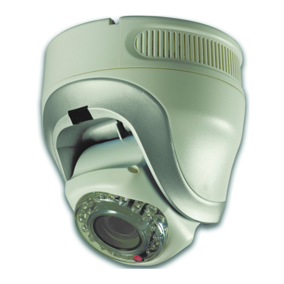
- Page 3 Thank you for purchasing this High Resolution Mini PTZ Dome Camera. Lorex is committed to providing our customers with a high quality, reliable security product. This camera features a 1/4" Color Sony CCD with IR Night Vision and 3X optical zoom.
- Page 4 General Precautions 1. All warnings and instructions of this manual should be followed. 2. Remove the plug from the outlet before cleaning. Do not use liquid aerosol detergents. Use a water dampened cloth for cleaning. 3. Do not use this unit in humid or wet places. 4.
- Page 5 Precautions on Installation Please ensure you have confirmed the following prior to installing the Mini Speed PTZ Camera: • Follow all local safety regulations • If connecting optional accessories, please make sure they are compatible and in complete working order. For a full list of optional accessories, visit www.lorexcctv.com •...
- Page 6 Setting Camera Codes and Protocols Prior to installation, setup ID address and communication protocol of your camera. Make sure the camera is powered OFF when resetting IDs or protocols after installation. When you have set the new IDs or protocols, power on the camera to implement the changes. Camera Self-Test Prior to mounting the camera, power on the camera to activate a self-test.
-
Page 7: Table Of Contents
Table of Contents Camera Features ............3 Operation Features . -
Page 9: Camera Features
Camera Features Camera Features • High Resolution 1/4" Color Sony CCD Camera • IR Night Vision • 3X Optical Zoom • Pan/Tilt Range of 355° horizontally and 90° vertically • Compact foot print—only 4.4" diameter • Pelco D/P and Eyeview Protocol Compatible Operation Features •... -
Page 10: Getting Started
Getting Started Getting Started The system comes with the following components: 1 X INDOOR MINI MULTI-SPEED 1 X MOUNTING BRACKET PTZ DOME CAMERA Optional accessories Included only with certain models. 1 X BNC/POWER/RS-485CABLE 1 X 60” BNC / POWER / RS-485 EXTENSION CABLE* 1 X DC POWER ADAPTOR* 3 X MOUNTING SCREWS... -
Page 11: Installing The Camera
Installing the Camera Installing the Camera There are two methods of installing the Mini Speed Dome Camera*: cable pass-through, or visible cable. Prior to installing the camera, make sure of the following: • You have powered-on the camera to run the automatic Self-Test (see Camera Self-Test page iv) •... -
Page 12: Visible Cable
Installing the Camera Visible Cable The visible cable method leaves the cable extending from the camera to the DVR, monitor, or observation system. This method is suggested if drilling a pass-through hole is not a viable option for installation. To install the camera: 1. -
Page 13: Rs-485 Wiring
Installing the Camera For both installation methods, double-check that the Mini Speed Dome Camera is firmly in place to prevent any risk of it falling down. Electrical Test Once the camera is mounted, connect the cables. If the camera is connected correctly and receiving sufficient power, it will automatically execute the Self-Test: the camera will tilt up/down, pan horizontally, and stop at Preset Point 1. -
Page 14: Rs-485 Aster Connection
Installing the Camera RS-485 Aster Connection This is the most common method in practical installation of PTZ cameras. In an Aster Connection, you need to use a RS-485 distributor to reduce interferance and stabilize the connections. Figure 3.1 Aster connection method Note: Without a RS-485 distributor, you risk causing a malfunction of the control signal or basic camera opeations... -
Page 15: Connecting The Camera
Connecting the Camera Connecting the Camera The Mini Speed Dome Camera works on a BNC channel of most DVRs and observation systems. Please refer to your observation system’s instruction manual for details on available channels for PTZ functionality. To connect the camera: 1. -
Page 16: Connectivity Diagram
Connecting the Camera Connecting to a DVR / Observation System (cont’d.) Connect to BNC input Note: BNC adaptors and/or RCA cable may be needed for some systems. • BNC-to-RCA adaptor • RCA cable • BNC-to-RCA adaptor Connect to RS-485 Connections: White: + (positive) Black —... -
Page 17: Changing The Camera Address Settings
Changing the Camera Address Settings Changing the Camera Address Settings The DIP switches inside the camera (1~10) can be changed to set a unique address for the camera (between 1~255). By default, the camera is set to channel 1. • If using a single camera, the address does not need to be changed. Refer to the Hardware Manual for the Observation System for camera channel placement and configuration. -
Page 18: Dip Switch Address Chart
Changing the Camera Address Settings DIP Switch Address Chart Address... - Page 19 Changing the Camera Address Settings DIP Switch Address Chart (cont.’d) Address...
- Page 20 Changing the Camera Address Settings DIP Switch Address Chart (cont.’d) Address...
- Page 21 Changing the Camera Address Settings DIP Switch Address Chart (cont.’d) Address...
- Page 22 Changing the Camera Address Settings DIP Switch Address Chart (cont.’d) Address...
- Page 23 Changing the Camera Address Settings DIP Switch Address Chart (cont.’d) Address...
- Page 24 Changing the Camera Address Settings DIP Switch Address Chart (cont.’d) Address...
- Page 25 Changing the Camera Address Settings DIP Switch Address Chart (cont.’d) Address...
- Page 26 Changing the Camera Address Settings DIP Switch Address Chart (cont.’d) Address...
-
Page 27: Appendix 1: Technical Specifications
Appendix 1: Technical Specifications Appendix 1: Technical Specifications Resolution 480 TV lines Lens Zoom Type: 2.8~7.3 mm Effective Pixels 786K(H) x 494K(V) Video Output 1.0V p.p (75 ohms) Scanning System 525 lines; 2:1 interlace PTZ Protocol Pelco-D, Pelco-P Supported Baud Rate 2400 (Pelco-D);... -
Page 28: Appendix 2: Troubleshooting
Appendix 2: Troubleshooting Appendix 2: Troubleshooting Error Possible Causes Solutions Camera runs • Keyboard or DVR • Make sure protocols on keyboard or DVR match Self-Test when first communication protocol is not the those of the camera powered on, but same as that of the camera cannot be controlled •...
Need help?
Do you have a question about the SG7382 and is the answer not in the manual?
Questions and answers