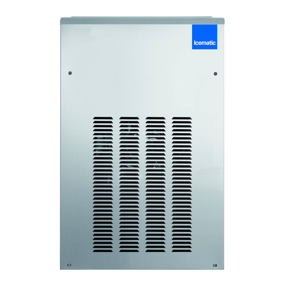
Icematic F 80 C Service Manual

Icematic F 80 C Service Manual

Electronic modular flakers and superflakers

Advertisement

ELECTRONIC MODULAR
FLAKERS AND SUPERFLAKERS
F
F 125 C
F 120
F 200
SF 300
SF 500
SFN 1000
Gas R134a - R 404a
NEW PC BOARD VERSION
I NOSTRI IMPIANTI SONO CONFORMI ALLA DIRETTIVA 73/23 CEE - 89/336
SERVICE MANUAL
80 C
Cod. 71503496/0- Rev. 001 - 04/2008
Advertisement

Table of Contents
loading

Summary of Contents for Icematic F 80 C

  • Page 1 ELECTRONIC MODULAR FLAKERS AND SUPERFLAKERS 80 C F 125 C F 120 F 200 SF 300 SF 500 SFN 1000 Gas R134a - R 404a NEW PC BOARD VERSION I NOSTRI IMPIANTI SONO CONFORMI ALLA DIRETTIVA 73/23 CEE - 89/336 SERVICE MANUAL Cod.
  • Page 3: Table Of Contents

    TABLE OF CONTENTS Specification F 80C pagina Specification F 125C Specification F 120 Specification F 200 Specification SF 300 Specification SF 500 Specification SFN 1000 GENERAL INFORMATION AND INSTALLATION Introduction Unpacking and Inspection - Ice maker Unpacking and Inspection - Storage bin Location and levelling Electrical connections Water supply and drain connection...
  • Page 4 Via del Lavoro, 9 C.P. 172 Tel. +39 0423 738452 icematic@castelmac.it I - 31033 Castelfranco Veneto (TV) Fax +39 0423 722811 F200 www.castelmac.it ITALY EU Fabbricatori di ghiaccio granulare Ice flakers Flockeneisbereiter Machines à glace en grains Fabricadores de hielo in escamas...
  • Page 5: General Information And Installation

    2 above. cleaning for the ICEMATIC F80C-F125C- F120-F200-SF300-SF500-SFN1000 Modular Remove all internal support packing and Icemakers. The Electronic Flakers and Super- masking tape.
  • Page 6: Location And Levelling

    Do not put any stiffeners crossing the ice misuse under the terms of the ICEMATIC drop opening. Manufacturer’s Limited Warranty resulting in LOSS of warranty coverage.
  • Page 7: Electrical Connections

    Remove the tape and fasten the catch using the two self-tapping screws supplied. WATER SUPPLY - WATER COOLED MODELS The water cooled versions of ICEMATIC Ice Makers require two separate inlet water supplies, ELECTRICAL CONNECTIONS one for the water making the flaker ice and the other for the water cooled condenser.
  • Page 8: Installation Pratice

    Have the bin liner and cabinet been wiped clean? 12. Has the owner been given the name and the phone number of the authorized ICEMATIC 10. Has the owner/user been given the User Service Agency serving him? G. INSTALLATION PRACTICE 1.
  • Page 9: Operating Instructions

    OPERATING INSTRUCTIONS START UP Elapsed the stand by period the unit starts operating with the activation in sequence of the following assemblies: After having correctly installed the ice maker and completed the plumbing and electrical GEAR MOTOR/S connections, perform the following “Start-up” pro- COMPRESSOR cedure.
  • Page 10 FIG. 2 WATER LEVEL RESET GEAR MOTOR ROTATION CONTACTOR COIL RELAYS CONDENSER TEMP. T 40÷50°C EVAPORATOR TEMP. GEAR MOTOR ICE LEVEL CONTROL TRIAC FAN MOTOR TRANSF. ELECTRONIC CARD FIG. 3 WATER LEVEL RESET GEAR MOTOR ROTATION CONTACTOR COIL RELAYS CONDENSER TEMP. EVAPORATOR TEMP.
  • Page 11: Operations Checks

    NOTE. On air cooled models, the condenser NOTE. If, after ten minutes from the compressor start-up, the evaporating tem- temperature sensor, which is located within perature has not dropped down to a value the condenser fins, keeps the head (condensing) pressure between preset lower than -1 °...
  • Page 12 This will cause a gradual decrease of the water After 3 minutes the unit resumes its total operation level in the float reservoir and as soon as the with the immediate start-up of the gear motor level gets below the two vertical metal pins, the and, few seconds later, of the compressor.
  • Page 13 NOTE. The ICE LEVEL CONTROL NOTE. In the front of the PC Board is located (INFRARED SYSTEM) is independent of the a small I/R Trimmer directly connected with temperature however, the reliability of its the optical Ice level control. By means of its detection can be affected by external light screw it is possible to modify the signal radiations or by any sort of dirt and scale...
  • Page 14: Principle Of Operation (How It Works)

    PRINCIPLE OF OPERATION WATER CIRCUIT F120-F200 The water enter in the machine through the ICE SPOUT water inlet fitting which incorporates a strainer - FLOAT TANK located at the rear side of the cabinet - then it FLOAT VALVE goes to the water reservoir flowing through a float valve.
  • Page 15: Refrigerant Circuit

    By running the ice maker, i.e. by putting the unit This condenser temperature sensor, when senses under power, starts the automatic and continuous a rising of the condenser temperature beyond icemaking process which would not stop until the the pre-fixed limit, changes its electrical resistance and send a low voltage power flow to the MICRO- ice storage bin gets filled-up to the level of the PROCESSOR of the P.C.
  • Page 16 tube connected to the liquid refrigerant line. As The RED LED starts blinking and three pressure increases, the water regulating valve minutes later the flaker unit resume its normal opens to increase the flow of cooling water to the operating mode. The condenser temperatu- condenser.
  • Page 17: Mechanical System

    MECHANICAL SYSTEM restart the unit it is necessary to press the RE-SET push button or switch OFF and ON The mechanical system of the ICEMATIC the power line main disconnnect switch Flaker machines consists basically of a gear (Fig. 7).
  • Page 18: Operating Pressures

    REFRIGERANT METERING DEVICE: REFRIGERANT CHARGE (R 404 A) Air cooled Water cooled capillary tube F200 660 gr 520 gr SF300 750 gr 600 gr SF500 880 gr 820 gr SFN1000 2400 gr 1200 gr REFRIGERANT CHARGE (R 134 A) NOTE. Before charging the refrigerant system Air cooled Water cooled always check the type of refrigerant and quantity...
  • Page 19: Components Description

    COMPONENTS DESCRIPTION In the event the condenser temperature rises and reaches 60 ° C or 70 ° C according to the EVAPORATOR TEMPERATURE setting of DIP SWITCH number 8 the current SENSOR arriving to the micro processor is such to cause an immediate and total stop of the machine operation.
  • Page 20 infrared sensor of ice level control - YELLOW LED YELLOW LED blinks fast) 6 seconds later the ice machine resumes Unit shut-off due to a its operation with the simul-taneous extinguishing too lo-water level into the 2nd YELLOW LED. float tank RED LED P.C.
  • Page 21 the cooling coil with the evaporating chamber G. JUMPERS and in its interior is located the auger which The Flaker PC Board is equipped by three jumpers: rotates on its vertical axis and it is maintained J1 · TEST: Used in the factory to energise all aligned by the top and bottom bearings.
  • Page 22 FAN MOTOR (Air cooled version) As pressure increases, the water regulating valve opens to increase the flow of cooling The fan motor is controlled through the TRIAC of water. the P.C. BOARD by the condenser temperature sensor. Normally it operates to draw cooling air through the condenser fins.
  • Page 23: Adjustment, Removal And Replacement Procedures

    ADJUSTMENT, REMOVAL AND REPLACEMENT PROCEDURES REPLACEMENT OF THE GEAR MOTOR NOTE. Read the instructions throughly MAGNETIC SENSOR before performing any of the following On F120, F200, SF300 and SF500 adjustment or removal and replacement pro- remove the front/top and side/rear panels and cedure.
  • Page 24: Replacement Of The Gear Motor Assy

    Grasp the icebreaker and remove the icebreaker and auger assembly by lifting them from the NOTE. It is good practice to replace the water evaporator. seal assy and both the top and the bottom bearings any time the auger is removed. To facilitate this it is available a service Kit NOTE.
  • Page 25: Replacement Of Freezing Cylinder

    Unsolder and disconnect the capillary tube Follow the steps of item E to remove the gear motor magnetic sensor. and the accumulator/suction line assy from the outlet line of the freezing cylinder. Trace and disconnect the electric wires leads of the drive motor. Lift and remove the Remove the three/four bolts and washers entire gear motor assembly.
  • Page 26: Wiring Diagram

    WIRING DIAGRAM F120 - F200 AIR AND WATER COOLED 230/50/1 GV - YELLOW GREEN B - WHITE G - GREY N - BLACK A - BLUE M - BROWN V - GREEN...
  • Page 27 WIRING DIAGRAM SF300 - SF500 AIR AND WATER COOLED SINGLE PHASE GV - YELLOW GREEN B - WHITE G - GREY N - BLACK A - BLUE M - BROWN V - GREEN...
  • Page 28 WIRING DIAGRAM SF500 AIR AND WATER COOLED THREE PHASE GV - YELLOW GREEN B - WHITE G - GREY N - BLACK A - BLUE M - BROWN V - GREEN...
  • Page 29 WIRING DIAGRAM SFN1000 AIR AND WATER COOLED GV - YELLOW GREEN B - WHITE THREE PHASE G - GREY N - BLACK A - BLUE M - BROWN V - GREEN...
  • Page 30: Service Diagnosis

    SERVICE DIAGNOSIS Unit will not run Blown fuse in P.C.Board Replace fuse & check for cause of g i l Master switch in OFF position Turn switch to ON position Inoperative P.C.Board Replace P.C.Board Loose electrical connections Check wiring Bin full yellow LED glows with Inoperative or dirty ice level control Replace or clean ice level control no ice in the bin No water yellow LED glows...
  • Page 31 SERVICE DIAGNOSIS Under or overcharge of refrigerant Recharge with correct quantity High water level in the freezer Lower to approx. 20 mm below ice spout Faulty compressor Replace Worn out of the auger Replace Machine runs but makes no ice Water not entering in the freezer Air look in feed line to freezer.
  • Page 32: Maintenance And Cleaning Instructions

    MAINTENANCE AND CLEANING INSTRUCTIONS This should cause the immediate blinking of the GENERAL Bin Full YELLOW LED located in the front of P.C. Board and, 6 seconds later, the total stopping of The periods and the procedures for maintenance the ice maker with the simultaneous light up of and cleaning are given as guides and are not to the same LED (steady).
  • Page 33 Then refit the water hose to the freezer water inlet port. 13. Pour into the water reservoir 1 cc. (approx 20 drops) of Icematic Sanitiser (Antialgae P/N Prepare the cleaning solution by diluting in CF 264000.00) then switch the unit ON.

This manual is also suitable for:

F 125 cF 120F 200Sf 300Sf 500Sfn 1000

Table of Contents