Table of Contents

Related Manuals for Icematic F 125C


Summary of Contents for Icematic F 125C
- Page 1 ELECTRONIC MODULAR FLAKERS AND SUPERFLAKERS 80 C F 125 C F 120 F 200 SF 300 SF 500 SFN 1000 Gas R134a - R 404a New PC board version SERVICE MANUAL I NOSTRI IMPIANTI SONO CONFORMI ALLA DIRETTIVA 73/23 CEE - 89/336 Cod.
- Page 2 FLAKERS STATUS REASON WHY - SIGNIFICATION - SIGNIFICATO F125C F80C F120÷SFN1000 ON STEADY UNTIL UNDER POWER FIXE SOUS TENSION FISSO IN TENSIONE ON STEADY UNIT OFF AT BIN FULL FIXE CABINE PLEINE FISSO CONTENITORE PIENO BLINKING SLOW I/R BEAM CUTTED CLIGNOTANT LENT FAISCEAU INFRA ROUGE CELLULE NIVEAU GLACE INTERROMPU LAMPEGGIANTE LENTO...
-
Page 3: Table Of Contents
TABLE OF CONTENTS Specification F 80C pagina Specification F 125C Specification F 120 Specification F 200 Specification SF 300 Specification SF 500 Specification SFN 1000 GENERAL INFORMATION AND INSTALLATION Introduction Unpacking and Inspection - Ice maker Unpacking and Inspection - Storage bin... - Page 4 F80C F80C F80C Fabbricatori di ghiaccio Granulari : F80C - F125C - F120 - F200 - SF300 - SF500 - SFN1000 Fabbricatori di ghiaccio Granular Fabbricatori di ghiaccio Granular F80C - F125C - F120 - F120 - F200 - SF300 - SF500 - SFN1000 SFN1000...
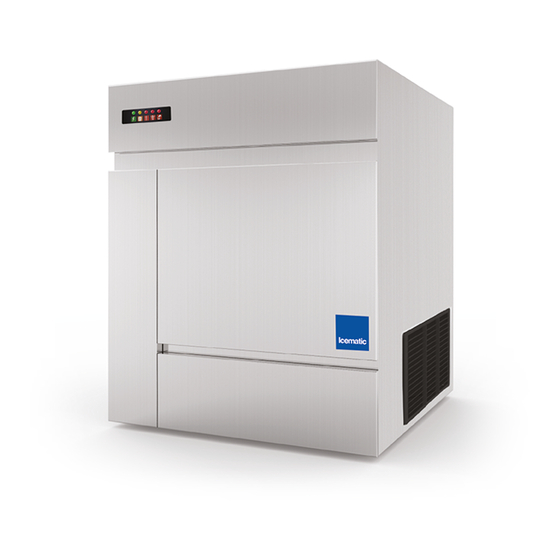
- Page 5 F125C F125C F125C Fabbricatori di ghiaccio Granulari : F80C - F125C - F120 - F200 - SF300 - SF500 - SFN1000 Fabbricatori di ghiaccio Granular Fabbricatori di ghiaccio Granular F80C - F125C - F120 - F120 - F200 - SF300 - SF500 - SFN1000 SFN1000...
- Page 6 F120 F120 F120 Fabbricatori di ghiaccio Granulari : F80C - F125C - F120 - F200 - SF300 - SF500 - SFN1000 Fabbricatori di ghiaccio Granular Fabbricatori di ghiaccio Granular F80C - F125C - F120 - F120 - F200 - SF300 - SF500 - SFN1000 SFN1000...
- Page 7 F200 F200 F200 Fabbricatori di ghiaccio Granulari : F80C - F125C - F120 - F200 - SF300 - SF500 - SFN1000 Fabbricatori di ghiaccio Granular Fabbricatori di ghiaccio Granular F80C - F125C - F120 - F120 - F200 - SF300 - SF500 - SFN1000 SFN1000...
- Page 8 SF300 SF300 SF300 Fabbricatori di ghiaccio Granulari : F80C - F125C - F120 - F200 - SF300 - SF500 - SFN1000 Fabbricatori di ghiaccio Granular Fabbricatori di ghiaccio Granular F80C - F125C - F120 - F120 - F200 - SF300 - SF500 - SFN1000 SFN1000...
- Page 9 SF500 SF500 SF500 Fabbricatori di ghiaccio Granulari : F80C - F125C - F120 - F200 - SF300 - SF500 - SFN1000 Fabbricatori di ghiaccio Granular Fabbricatori di ghiaccio Granular F80C - F125C - F120 - F120 - F200 - SF300 - SF500 - SFN1000 SFN1000...
- Page 10 SFN1000 SFN1000 SFN1000 Fabbricatori di ghiaccio Granulari : F80C - F125C - F120 - F200 - SF300 - SF500 - SFN1000 Fabbricatori di ghiaccio Granular Fabbricatori di ghiaccio Granular F80C - F125C - F120 - F120 - F200 - SF300 - SF500 - SFN1000 SFN1000...
-
Page 11: General Information And Installation
1 Call your authorized Distributor or Dealer for startup and operation, maintenance and clea- proper installation. ning for the ICEMATIC F80C-F125C-F120-F200- 2 Visually inspect the exterior of the packing SF300-SF500-SFN1000. and skid. Any severe damage noted should... -
Page 12: Location And Levelling
Storage bin “UD” series 9 Remove the manufacturer’s registration card from the inside of the User Manual and fillin 1 Follow the steps 1, 2 and 3 above to unpack all parts including: Model and Serial Number the storage bin. taken from the data plate. -
Page 13: Electrical Connections
1. Position the storage bin in the selected per- 8 Position and install the four aluminium front to manent location. rear stiffeners (U shaped) paying attention to Criteria for selection of location include: the guideline shown on the drawing. a) Minimum room temperature 10°C (50°F) and maximum room temperature 40°C (100°F). -
Page 14: Water Supply And Drain Connection
WATER SUPPLY - WATER COOLED MODELS damage to the overload switch and motor win- dings. The water cooled versions of Ice Makers requi- re two separate inlet water supplies, one for the NOTE. All external wiring should conform to water making the flaker ice and the other for the water cooled condenser. -
Page 15: Final Ceck List
F. FINAL CHECK LIST 8 Check all refrigerant lines and conduit lines 1 Is the unit in a room where ambient tempera- to guard against vibrations and possible fai- tures are within a minimum of 10°C (50°F) lure. even in winter months? 9 Have the bin liner and cabinet been wiped 2 Is there at least a 15 cm (6") clearance clean? -
Page 16: Operating Instructions
OPERATING INSTRUCTIONS START UP B Elapsed the stand by period the unit starts After having correctly installed the ice maker operating with the activation in sequence of and completed the plumbing and electrical the following assemblies: GEAR MOTOR/S connections, perform the following “Start-up” procedure. -
Page 18: Operations Checks
NOTE. f, after ten minutes from the compressor NOTE. On air cooled models, the condenser dropped down to a value lower than -1°C (30°F) start-up, the evaporating temperature has not temperature sensor, which is located within the condenser fins, keeps the head (condensing) the evaporating temperature sensor detects pressure between preset values. - Page 19 E Check for the correct CUT-OUT and CUT-IN Opening the water supply line shutoff valve to of the water level sensor by first shutting fill up again the float reservoir, the YELLOW LED goes off while the RED LED starts closed the water shutoff valve on the water blinking.
- Page 20 NOTA. The ICE LEVEL CONTROL (INFRA- NOTA. During the life of the machine the Ice RED SYSTEM) is independent of the tempe- Level Control may require a recalibration rature however, the reliability of its detection mainly when the glass of the two optical eyes can be affected by external light radiations or are covered by a thin lay of scale.
-
Page 21: Principle Of Operation (How It Works)
PRINCIPLE OF OPERATION PRINCIPLE OF OPERATION WATER CIRCUIT WATER CIRCUIT The water enter in the machine through the ICE SPOUT The water enter in the machine through the water inlet fitting which incorporates a strainer - FLOAT TANK PRINCIPLE OF OPERATION located at the rear side of the cabinet - then it water inlet fitting which incorporates a strainer - FLOAT VALVE... -
Page 22: Refrigerant Circuit
By running the ice maker, i.e. by putting the unit suction accumulator and through the suction line under power, starts the automatic and conti- where the refrigerant exchanges heatwith the nuous icemaking process which would not stop one flowing into the capillary tube (warmer) befo- until the ice storage bin gets filled-up to the rebeingsuckedinto thecompressor to be recircu- level of the control “eyes”... - Page 23 NOTE. In case the condenser temperature The machine will remain in OFF mode for one probe senses that the condenser temperature hour then it will restart automatically. has rised to 70°C on air cooled version - or In case the unit trips OFF again in alarm for 3 60°Conwater cooled version - for one of the fol- times in 3 hours, the machine SHUTS OFF DEFI- CLOGGED CONDENSER (Air cooled version)
-
Page 24: Mechanical System
NOTE In the event the gear motor (one of NOTE If, after tenminutes fromthe unit start the two on MF 66) will tend to rotate in the up, no ice is made and the evaporating wrong direction (counterclockwise) or not temperature detected by the evaporator rotating at all or rotating at lower speed the sensor results to be higher than -1°C (30°F) -
Page 25: Operating Pressures
F 80C 300 gr 300 gr freezer) may cause the ice to get too hard and F 125C 400 gr 300 gr compact loosing fluidity and thereby seizing the F 120... -
Page 26: Components Description
COMPONENTS DESCRIPTION This sensor system causes the shutoff of the A EVAPORATOR TEMPERATURE SENSOR machine, to protect it from running without The evaporator sensor probe is inserted into its tube well, which is welded on the evaporator this situation the YELLOW LED will glow to water or with an inadequate water quality. - Page 27 NOTE. During the life of the machine the Ice D ELECTROMAGNETIC SENSOR This safety device is housed on top of the Drive Level Control may require a recalibration Motor and detects - based on Hall Effect princi- mainly when the glass of the two optical eyes ple - the rotating speed and rotating direction of are covered by a thin lay of scale.
- Page 28 F P.C. BOARD (Data processor) YELLOW LED The P.C. BOARD, fitted in its plastic box located Unit shut-off due to a too in the front of the unit, consists of two separated lo-water level into float tank RED LED printed circuits one at high and the other at low voltage and protected by fuses.
- Page 29 YELLOW AND RED LED J6 = 60/70 °C Set up of the Safety Condensing - Blinking: Evaporator sensor Temperature Sensor out of order JUMP IN - 70°C - Steady: Condenser sensor JUMP OUT - 60°C out of order H. INTERFACE P.C. BOARD - Blinking alternatively: Ice level (Only on SFN1000) control out of order...
- Page 30 J FREEZING CYLINDER or EVAPORATOR (Two on SFN 1000) (MOBILPLEX IP 44). Two seal rings, one fitted on the rotor shaft and the other on the output shaft keep the gear case sea- The freezing cylinder is made of a stainless steel vertical tube on which exterior is wrapped around led.
-
Page 31: Adjustment, Removal And Replacement Procedures
ADJUSTMENT, REMOVAL AND REPLACEMENT PROCEDURES WARNING. Be sure the electrical power NOTE. Read the instructions throughly befo- supply circuit breaker and the inlet water supply are OFF, before starting any of the re performing any of the following adjustment following Removal and Replacement pro- or removal and replacement procedure cedures as a precaution to prevent possi- ble personal injury or damage to the equip-... - Page 32 C REPLACEMENT OF THE AUGER, WATER WARNING. The top bearing assembly SEAL, BEARINGS AND COUPLING works in critical conditions for what con- cern its lubrication as it is haused in the 1 Remove thepanels. ice breaker where the formation of con- 2 Followthe steps at item H to remove the ice densation is usual.
- Page 33 13 Reach through the adaptor and remove the leads of the drive motor. Lift and remove the coupling parts. entire gear motor assembly. 14 Check both the coupling halves for chipping 5 To install the replacement gear motor assy and wear and do not hesitate to replace follow the above steps in reverse.
-
Page 35: Wiring Diagram
WIRING DIAGRAM F 80C Air cooled 220-240/50/1... - Page 36 WIRING DIAGRAM F 80C Water cooled 220-240/50/1...
- Page 37 WIRING DIAGRAM F 125C Air / water cooled 220-240/50/1...
- Page 38 WIRING DIAGRAM F 120 - F 200 Air / water cooled 220-240/50/1...
- Page 39 WIRING DIAGRAM SF 300 - SF 500 Air / water cooled 220-240/50/1...
- Page 40 WIRING DIAGRAM SF 500 Air / water cooled 400/50/3...
- Page 41 WIRING DIAGRAM SFN 1000 Air / water cooled 400/50/3...
-
Page 42: Service Diagnosis
SERVICE DIAGNOSIS SYMPTON POSSIBLE CAUSE SUGGESTED CORRECTION Unit will not run Blown fuse in P.C.Board Replace fuse & check for cause of No LED lighted-on blown fuse Master switch in OFF position Turn switch to ON position Inoperative P.C.Board Replace P.C.Board Loose electrical connections Check wiring Bin full yellow LED glows... - Page 43 SYMPTOM POSSIBLE CAUSE SUGGESTED CORRECTION Wet ice Ambient temperature too high Move unit to cooler location Under or overcharge of refrigerant Recharge with correct quantity High water level in the freezer Lower to approx. 20 mm below ice spout Faulty compressor Replace Worn out of the auger Replace...
-
Page 44: Maintenance And Cleaning Instructions
MAINTENANCE AND CLEANING INSTRUCTIONS A GENERAL 6 If required, polish the two sensor rods secu- The periods and the procedures for maintenan- red to the float reservoir cover, heavy scale ce and cleaning are given as guides and are sediment on them can be removed with the not to be construed as absolute or invariable. -
Page 45: Cleaning Instructions Of Water System
NOTE. Put one or both of the water sensor on 13Remove the retaining ring and the hook and cap from the top of the freezer assembly then the casing of the equipment, because in this inspect the top bearing, wipe clean of all way through the condenser sensor voltage grease and apply a coating of food grade will be transferred and the equipment will be... - Page 46 NOTE. The ice produced with the decalcifi- cation solution is yellowish and smooth. In this phase, there are loud noises from the freezer due to the rubbing between the rising ice and the evaporator walls. In this case, it is recommended that the equipment should be switched off for some minutes, so that the decalcification solution in the freezer can be...
- Page 48 Via del Lavoro, 9 C.P. 172 I - 31033 Castelfranco Veneto (TV) Italy Tel. +39 0423 738455 - Fax +39 0423 722811 E-mail: service@castelmac.it Web-site: www.castelmac.it Cod. 71503496/0- Rev. 002 - 05/2015...
Need help?
Do you have a question about the F 125C and is the answer not in the manual?
Questions and answers