Advertisement
Table of Contents
- 1 Table of Contents
- 2 Important Safety Instructions
- 3 Notice for Installation
- 4 Minimum Floor Areas
- 5 Components
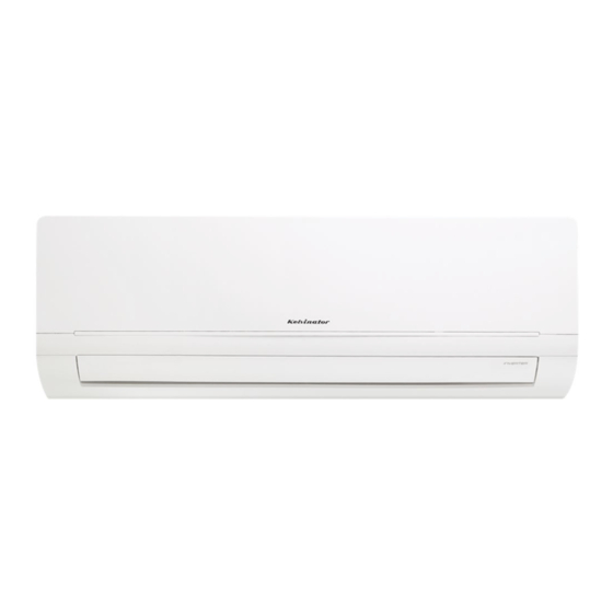
- 6 Product Description
- 7 Installation Site Instructions
- 8 Rooftop Installation
- 9 Outdoor Unit Installation
- 10 Indoor Unit Installation
- 11 Installation
- 12 Testing the Air Conditioner
- 13 Installation Checklist
- 14 Post Installation Checks
- 15 Warranty
- Download this manual
Advertisement
Table of Contents


Need help?
Do you have a question about the KSV25CRF and is the answer not in the manual?
Questions and answers