Advertisement
KTI63194A
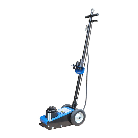
22 TON CAPACITY AIR/HYDRAULIC TRUCK JACK
OWNERS MANUAL
Capacity ............................................................22 Ton
Low Height ...........................................................................9"
Ram Travel ........................................................................... 4-3/4"
Ext. Screw Adj. ..................................................................... 4-1/4"
Max. Height with Adapter ..................................................18"
KTI63194A
WARNING: Cancer and Reproductive Harm
- www.P65Warnings.ca.gov
SPECIFICATIONS
Complies with ASME PALD/2009 Safety Standard
Overall Width ...................................................................... 13"
Saddle Diameter .................................................................. 1-3/4"
Wheel Diameter ..........................................................................8"
Handle Length ......................................................................48-2/5"
Shipping Weight ..................................................................105.8 Lbs.
1
Advertisement
Table of Contents

Subscribe to Our Youtube Channel
Related Manuals for K Tool International HD KTI63194A


Summary of Contents for K Tool International HD KTI63194A
- Page 1 KTI63194A 22 TON CAPACITY AIR/HYDRAULIC TRUCK JACK OWNERS MANUAL WARNING: Cancer and Reproductive Harm - www.P65Warnings.ca.gov SPECIFICATIONS Capacity ............22 Ton Overall Width ..............13" Low Height ................9" Saddle Diameter ..............1-3/4" Ram Travel ................4-3/4" Wheel Diameter ................8" Ext. Screw Adj..............4-1/4" Handle Length ..............48-2/5"...
-
Page 2: Warning Information
WARNING INFORMATION This is the safety alert symbol. It is used to alert you to WARNING: Indicates a hazardous situation WARNING potential personal injury hazards. Obey all safety messages which, if not avoided, could result in death that follow this symbol to avoid possible injury or death. or serious injury. - Page 3 SETUP PLEASE REFER TO THE EXPLODED VIEW DRAWING IN THIS MANUAL IN ORDER TO IDENTIFY PARTS. 1. Feed the black hose (#64) and orange hose (#63) coming out of the bottom of the handle assembly (#76) through the handle-1 (#52) while at the same time lining up the hole in the handle-1 (#52) with the hole in the handle connector (#55). Secure them together with the screw (#54). 2. Thread two nuts (#53) all the way on the bottom of the tie rod (#50). Thread the bottom of the tie rod all the way inside the slotted pin (#49). Now tighten one nut (#53) down on top of the slotted pin (#49) and tighten. Slip the spring (#51) down on the tie rod (#50). Insert the tie rod (#50) through the bottom of the bracket that is welded to the handle-1 (#52) so that the spring is trapped between the bracket and the nuts (#53) that are tightened against the slotted pin (#49). Compress the spring until the cross hole in the tie rod (#50) is visible on the other side of the welded bracket and install the r-pin (#71) through the hole. 3. Thread another nut (#53) all the way on the tie rod (#56). Hold the handle lock (#58) down and away from the t-handle-2 (#60) while simultaneously threading the tie rod (#56) nut onto the tie rod (#50). 4. Raise the handle lock (#58) up so the slotted pin (#49) does not come in contact with any of the three holes in the handle position seat assembly (#7). Remove the screw (#73) from the handle socket (#11). Insert the handle-1 (#52) in the handle socket (#11) while simultaneously inserting the slotted pin (#49) in the handle socket (#11) guide holes. Make sure the hole in the lower portion of the handle-1 (#52) aligns with the threaded hole in the handle socket (#11) and secure them together with the screw (#73). Move the handle up and down while simultaneously pulling the handle lock down so the slotted pin (#49) will engage with any of the three locking holes in the handle position seat assembly (#7). Make sure the slotted pin will engage all three holes. It might be necessary to adjust the threaded connection between tie rods (#50 and #56) in order to get proper engagement. After final adjustment, tighten the nut (#53) to secure the connection. 5. There are two air hoses that must be firmly inserted into the couplers (#48). The orange hose (#63) fits in the higher located coupler while the black hose (#64) fits in the lower located coupler. 6. Install the air quick disconnect of your choice in the cross valve (#65). Put at least two wraps of pipe dope tape around the disconnect threads before installation to prevent air leaks.
-
Page 4: Preventative Maintenance
PREVENTATIVE MAINTENANCE This is the safety alert symbol used for the PREVENTATIVE MAINTENANCE section of this manual to alert you to potential personal injury hazards. Obey all instructions to avoid possible injury or death. IMPORTANT: The number one cause of jack failure in air/hydraulic jacks is dirt and moisture in the air motor and/or hydraulic system. maintenance schedule. -
Page 5: Warranty
WARRANTY K-Tool international HD and XD service-related equipment 2 Year Limited Warranty. K-Tool International warrants that all jacks and service-related equipment will be free from defects in material and workmanship for a period of 2 years following the original date of purchase. This warranty is extended to the original retail purchaser only. If any jack or service-related item proves to be defective during this period, it will be replaced or repaired, at K-Tool International’s option, without charge. - Page 6 KTI63194 22 Ton CAPACITY AIR/HYDRAULIC TRUCK jACK ExPLOdEd dRAWINg KTI63194A...
-
Page 7: Parts List
KTI63194A 22 TON CAPACITY AIR/HYDRAULIC TRUCK JACK PARTS LIST REF. # PART # DESCRIPTION QTY. REF. # PART # DESCRIPTION QTY. Bolt Block Bolt Coupler Bolt Coupler KTP63194A04 Short Orange Hose KTP63194A05 Washer Short Black Hose KTP63194A06 Wheel Orange Hose Handle Position Seat Assy Coupler Base Plate...
Need help?
Do you have a question about the HD KTI63194A and is the answer not in the manual?
Questions and answers