Advertisement
Quick Links
LEAK DETECTION
powered by
Installation items (not supplied)
• Wall fasteners for surface mounting (four screws)
Tools required
• Drill or hole punch for electrical conduit entries
• Phillips (cross-head) screwdriver
• Small flat-head screwdriver
Storage
Keep the module in a dry place prior to installation to avoid possible damage to internal components.
Product Information
TTDM-128
TTDM-128-24V
Power consumption
Installation categories
Built-in relays
Temperature
Enclosure
Approvals and Certifications
Type NM
LISTED
76LJ
SIGNAL SYSTEM UNIT
Shock hazard. Shut off power before operating enclosure door.
®
115 Vac +15%, –20%; 50/60 Hz
230 Vac ±10%; 50/60 Hz
24 Vac +5%, –35%
6 VA (5 W) for TTDM-128
12 VA (10 W) for TTDM-128-24V
Overvoltage Category II, Pollution Degree 2
Number:
Type:
Rating:
Storage:
Operating: 0°C to 50°C (32°F to 122°F)
NEMA 12; IP 54
General Information
Please read these instructions carefully and keep them in a safe place
(preferably close to the TTDM) for future reference. These instructions
must be followed carefully to ensure proper operation.
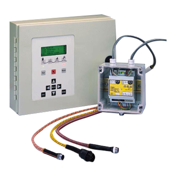
The TTDM Alarm and Locating Module has been designed specifically for use
with TraceTek sensing cables, point sensors, sensor interface modules and
relay modules. The TTDM can directly monitor up to 1500 m (5000 ft) of
sensing cable, and large networks of remote leak detection modules.
An external disconnect device and appropriate branch circuit protection
(no more than 20 amp rating) should be provided for the TTDM. The
disconnect device should be clearly marked as such. Follow all national
and local codes and regulations applicable to the installation.
24 Vdc ±20%
Three (Service, Leak, Fault)
DPDT
5 A at 250 Vac/24 Vdc
–18°C to 60°C (0°F to 140°F)
TTDM-128
TTDM-128
TraceTek Leak Detection
and Loction Module
TraceTek Leak Detection
and Location Module
Installation Instructions
Advertisement

Related Manuals for Raytech TraceTek TTDM-128

Summary of Contents for Raytech TraceTek TTDM-128
- Page 1 TTDM-128 TTDM-128 ® TraceTek Leak Detection LEAK DETECTION and Loction Module TraceTek Leak Detection powered by and Location Module Installation Instructions General Information Please read these instructions carefully and keep them in a safe place (preferably close to the TTDM) for future reference. These instructions must be followed carefully to ensure proper operation.
- Page 2 TTDM-128 Installation Instructions TraceTek TTDM Test Reset Menu Enter LCD display Sensor Interface board Gland plate RS-485 TraceTek Network Plug & Socket LEDs with icons Motherboard Fault relay cable plug and socket Ribbon cable Test key Power supply board Leak relay cable plug and socket Host port RS-232/485 selector Silence key Fuse (500 mA, 250 V, time delay)
- Page 3 TTDM-128 Installation Instructions Mounting the Enclosure Figure 3 300 mm Install the enclosure using the four screws in the prepunched 8 mm (5/16- (11.81 in) 20 mm inch) mounting holes with centers as shown in Figure 3. If plastic plugs (0.79 in) 261 mm are in the mounting holes, remove them.
-
Page 4: Testing The Module
TTDM-128 Installation Instructions Connect the alarm relays. SERVICE RELAY LEAK RELAY FAULT RELAY 15 16 17 21 22 23 27 28 29 The TTDM has three relays, for service , leak , and fault Each relay provides two Form-C relay contacts, and normally open and normally closed contacts are both provided. - Page 5 TTDM-128 Installation Instructions Connect the Sensing Cable If the TTDM will be used to monitor a sensor directly, follow these instructions to connect the sensor to the TTDM. If the TTDM is being used only as a network master, skip to Connecting the TraceTek Network. Prepare sensing cable.
-
Page 6: Connecting To A Host Computer
TTDM-128 Installation Instructions TT1100-OHP Connecting to a Host Computer Braided fiber jacket (8.2 mm diameter) Signal wires (2) There are 3 ways to connect the TTDM to a host computer: hard-wired Yellow tracer RS-232, hard-wired RS-485, or standard modular RS-232 cable. For permanent installations, the hard-wired method is recommended (either RS-232 or RS-485 as necessary).
Need help?
Do you have a question about the TraceTek TTDM-128 and is the answer not in the manual?
Questions and answers