Table of Contents
Advertisement
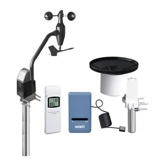
Wi-Fi Weather Station
Operation Manual
Model: GW1002
Thank you for purchasing this GW1002 Wi-Fi Weather Station, with
wireless anemometer, self-emptying rain collector, temperature and
humidity sensor.
This manual will guide you, step-by-step, through setting up your weather
station and console, and understanding the operation of your weather station.
Note:
The mounting pole for wireless anemometer is not included.
1
Advertisement
Table of Contents

Related Manuals for ECOWITT GW1002


Summary of Contents for ECOWITT GW1002
- Page 1 Wi-Fi Weather Station Operation Manual Model: GW1002 Thank you for purchasing this GW1002 Wi-Fi Weather Station, with wireless anemometer, self-emptying rain collector, temperature and humidity sensor. This manual will guide you, step-by-step, through setting up your weather station and console, and understanding the operation of your weather station.
-
Page 2: Table Of Contents
1 Table of Contents 1 TABLE OF CONTENTS 2 UNPACKING 3 OVERVIEW 3.1 USB G ATEWAY 3.2 W IRELESS ANEMOMETER ASSEMBLY WITH SOLAR SENSORS 3.3 R ENSOR 3.4 O UTDOOR TEMPERATURE AND HUMIDITY SENSOR 3.5 F EATURES 4 SET UP GUIDE 4.1 S URVEY 4.2 W... - Page 3 5.1 G ATEWAY ONFIGURATION 5.2 A DDING WEATHER SERVICES 5.3 E COWITT EATHER 5.3.1 Viewing data on ecowitt.net 5.4 W EATHER NDERGROUND 5.4.1 WU Dashboard vs Live Data 5.5 E DITING AIN TOTALS 5.5.1 Calibration of barometric pressure settings. 5.6 R EGISTERING WITH AND USING WUNDERGROUND 5.7 D...
-
Page 4: Unpacking
2 Unpacking Open your weather station box and inspect that the contents are intact (nothing broken) and complete (nothing missing). Inside you should find the following: Item Description USB Wi-Fi Gateway Cable clip Wireless anemometer body with built-in: Wind speed/direction sensor, Light and UV sensor, Solar panel Wind speed cups (to be attached to anemometer sensor body) Wind vane (to be attached to anemometer sensor body) - Page 5 Note: There are two sets of U-bolts in the box, one is for the wireless anemometer sensor and the other one is for the rain gauge sensor. There’s a short stainless-steel tube included for the rain gauge sensor installation. Note: The rain gauge can also be mounted to a surface using two screws, so the included stainless-steel tube is not always necessary!
-
Page 6: Overview
3 Overview 3.1 USB Gateway Figure 1: Wi-Fi Gateway 3.2 Wireless anemometer assembly with solar sensors Figure 2: Wireless anemometer, wind-vane, solar sensor... -
Page 7: Rain Sensor
3.3 Rain Sensor Figure 3: Self emptying rain gauge 3.4 Outdoor temperature and humidity sensor Figure 4: Outdoor temperature and humidity sensor display... -
Page 8: Features
https://www.ecowitt.net https://www.wunderground.com https://www.weathercloud.com/ https://www.wow.com Custom sites using either Wunderground or Ecowitt protocol. Contact the Customer Support department for assistance. Mobile application (WS View) View collected live data. Manage sensor calibration setup. ... - Page 9 Solar light intensity and UV index Note: All the optional sensors can all be found on our website: http://www.ecowitt.com. Make sure to select the model of the units with the same RF frequency as your gateway (the frequency is different for various countries because of regulations).
-
Page 10: Set Up Guide
4 Set up Guide Before you start, you will need a Philips screwdriver (size PH0, not provided) and find the wrench (size M5) included in package. Note: We suggest you assemble all components of the weather station, including (optional) console in one location so you can easily test functionality. After testing, place the outdoor sensors in the desired location. -
Page 11: Wireless Anemometer Package Assembly
Anemometer Ideally mounted at least 32 feet, or 10 meters above ground level. Try to make the anemometer the highest object around. 7 feet, or 2.75 meters) or more above the surrounding obstructions is best. Rain Gauge Ideally mounted at a height of 4 to 6 feet, or 1.5 to 2 meters above the ground. -
Page 12: Install U-Bolts And Metal Plate
Figure 5: Sensor package assembly components Anemometer cups LED (red) indicating data transmission Wind vane Light sensor and UV sensor Connection tube NORTH alignment indicator U-Bolts (2) Solar panel Mounting pole (not 10. Reset button included) Table 2: Sensor package assembly component list 4.2.1 Install U-bolts and metal plate Installation of the U-bolts, which are in turn used to mount the sensor package on a pole, requires installation of an included metal plate to receive... - Page 13 degree angle and has a curved profile (which will end up “hugging” the mounting pole). Once the metal plate is inserted, remove nuts from the U- Bolts and insert both U-bolts through the respective holes of the metal plate as shown in Figure 6. Figure 6: U-Bolt installation Loosely screw on the nuts on the ends of the U-bolts.
-
Page 14: Install Wind Vane
of the sensor package with wind vane and speed cups already installed to then install these bolts is more difficult and more likely to lead to damage. 4.2.2 Install wind vane Push the wind vane onto the shaft on the bottom side of the sensor package, until it goes no further, as shown on the left side in Figure 8. -
Page 15: Install Batteries In Sensor Package
Figure 9: Wind speed cup installation diagram 4.2.4 Install batteries in sensor package Open the battery compartment with a screwdriver and insert 1 AA battery in the battery compartment. The LED indicator on the back of the sensor package (item 6) will turn on for 3 seconds and then flash once every 16.5 seconds indicating sensor data transmission. -
Page 16: Mount Wireless Anemometer Assembly
Note: If LED does not light up or is on permanently, make sure the battery is inserted the correct way and inserted fully, starting over if necessary. Do not install the battery backwards as it may permanently damage the outdoor sensor. - Page 17 Figure 11: Sensor package mounting diagram Make sure the mounting pole is vertical, or very close to it. Use a level as needed. Finally, place the sensor package on top of the prepared mounting pipe. The U-Bolts should be loose enough to allow this but loosen the nuts as necessary.
-
Page 18: Reset Button And Transmitter Led
capacitors. Secondly it causes a zero reading for wind direction to correspond to due NORTH, as is customary. Note: When installing in a location on the southern hemisphere, the north indicator should actually be made to point due south so that the solar panel will receive optimal sunlight. -
Page 19: Install Rain Gauge Filter
Figure 12: Sensor assembly components Rain collector top Battery compartment door LED Indicator Surface installation screw hole Bubble level U-bolt installation hole Table 3: Sensor assembly detailed items 4.3.1 Install rain gauge filter There’s a stainless steel filter included in the package. It’s aimed to stop leaves or bird's dropping to avoid the obstruction of the cone hole. -
Page 20: Install Rain Collector Top
Take out the filter hook from the Hook the filter hook on the edge to edge to uninstall install Figure : Rain gauge filter in/un-installation diagram 4.3.2 Install rain collector top Align the rain collector top with the rain bucket, pay attention to the lock groove position as shown on the left side in Figure 13. -
Page 21: Mounting
Figure 14: Rain gauge sensor battery installation diagram The LED indicator on the top of the battery door (item 2) will turn on for 4 seconds and then flash once every 49 seconds indicating sensor data transmission. If you did not pay attention, you may have missed the initial indication. - Page 22 Mounting with U-bolts 4.3.4.2 The mounting assembly includes two U-Bolts and a bracket that tightens around a 1-2" diameter pole using the four U-Bolt and nuts. The package includes a D32/H200 (diameter 32mm = 1.26”, length 200mm = 7.87”) stainless steel tube for this purpose. Figure 15: Rain gauge installation with U-bolts Note: Use the bubble level one the side of the rain gauge as a guide to verify that...
-
Page 23: Outdoor Temperature And Humidity Sensor Set Up
Figure 16: Rain gauge sensor mounting with screws installation diagram Note: Use the bubble level beside the rain sensor as a guide to verify that the sensor is levelled. Use shims as necessary to achieve level installation. 4.4 Outdoor Temperature and Humidity Sensor Set Up Note: To avoid permanent damage, please take note of the battery polarity before inserting the batteries. -
Page 24: Sensor Placement
Figure 17: Indoor sensor battery installation 4.4.1 Sensor Placement The best mounting location for this sensor is in a location that never receives direct sunlight, not even through windows. Also, do not install in a location where a nearby radiant heat source (radiator, heaters, air-conditioning compressor etc.) will affect it. -
Page 25: Best Practices For Wireless Communication
Figure 18: Indoor sensor mounting Note: Make sure the sensor is mounted vertically and not lying down on a flat surface. This will insure optimum reception. Wireless signals are impacted by distance, interference (other weather stations, wireless phones, wireless routers, TVs and computer monitors), and transmission barriers, such as walls. -
Page 26: Wi-Fi Gateway Introduction
The frequencies used by the sensors are one of (depending on your location): 433, 868, or 915 MHz (915 MHz for United States). Line of Sight Rating. This device is rated at 300 feet line of sight (under ideal circumstances; no interference, barriers or walls), but in most real-world scenarios, including a wall or two, you will be able to go about 100 feet. -
Page 27: Led Indicators
Figure 19: Gateway Introduction Wi-Fi Configure/Reset Button RF Status Indicator Light (Blue) Wi-Fi Status Indicator Light (Red) USB Connector for system power supply Temperature, humidity and barometric 3-in-1 sensor Table 5: Gateway parts identification Before configuring the gateway with the mobile application, please read the description of the LED indicators (Items 2 and 3) and button (item 1) function for better understanding. -
Page 28: Button Functions
On (steady): indicates connected to Wi-Fi network; network communication normal and data uploaded to configured weather service(s) successfully. Off (steady): Wi-Fi connection failed. Flash (slowly), indicates connected to Wi-Fi network; network communication normal, but upload to one or more configured weather services failed. -
Page 29: Publish To Internet Weather Services
Ecowitt Weather Site: https://www.ecowitt.net Ecowitt’s new weather server that can host a bunch of sensors that other services don’t support at this time. Table 6: Supported weather services 5.1 Gateway Wi-Fi Configuration The gateway can function as an independent Wi-Fi access point during Wi- Fi configuration. - Page 30 1. Download the mobile application WS View from the iOS App Store or Google Play store, as appropriate for your device. 2. Plug your gateway into an available USB port that supplies power and ensure it is in Wi-Fi configuration mode (RED LED flashing fast). If it is not, follow the procedure to put it in that mode (hold down button for about 5 seconds).
- Page 31 Figure 20: Configure screen 6. Confirm Wi-Fi configuration mode is active, as prompted. Correct if necessary (see above). Press “Next”. 7. Enter your preferred Wi-Fi SSID (network name) and security password. Press “Next”. This will be communicated to the gateway in a later step. 8.
- Page 32 Figure 21: Live Data screen Note: If it displays a blank screen on the Device List instead of the “Live Data” screen, please check the following: Wait for 1-2 minutes and check whether the device will appear and go to the “Live Data” screen. ...
-
Page 33: Adding Weather Services
Try to turn off your mobile data/cellular data. Exit the app and close all the applications in process, then reopen the WS View app and back to the Device List If still not work, contact the customer service for support Note: the above and after figures are all from the iOS version application. - Page 34 Figure 20: Device List screen On the “Live Data” screen, press the “More” button in the upper right and select “Weather Services” from the menu.
- Page 35 Figure 21: Live Data screen with settings menu Navigate to the weather service you wish to configure by pressing “Next” and enter the appropriate data.
-
Page 36: Ecowitt Weather
Figure 22: Weather Services uploading setting screen 5.3 Ecowitt Weather It’s recommended to use the Ecowitt Weather server to monitor and record your sensors’ data. Configure as follows:... -
Page 37: Viewing Data On Ecowitt.net
Note: If you want to share your station data with other users, you’ll need to set your data to be public. Other users need to log in the ecowitt.net first to view your data. It will show a page such as this, where you can look at today’s data and... - Page 38 Dashboard Graph display...
- Page 39 List display Weather Map...
-
Page 40: Weather Underground
Email Alerts 5.4 Weather Underground If you are planning to use wunderground.com you must have an account and register a (new) personal weather station. You may do so on the Wunderground uploading page in the WS View application: Press Register at Wunderground.com and finish the registration on the page (you may choose “other”... -
Page 41: Wu Dashboard Vs Live Data
5.4.1 WU Dashboard vs Live Data You should be aware that the information presented on weatherunderground.com represents the latest as seen by WU (from the last successful upload), and may not be identical what is on your live data screen! Here is a short explanation of differences: Live Data is obtained by the mobile app by connecting directly to the gateway. - Page 42 Absolute barometric pressure can be calibrated at manufacturing time by comparing with a precise instrument that measures pressure at the same location. In practice, sometimes small adjustments of a few hPa may be needed. The relative pressure represents what the air pressure would indicate if your station was at sea level and depends on the altitude of your gateway and cannot be known in advance.
- Page 43 desk, you’ll have to add something like 3-4 ft. If you are using a GPS system that tells you elevation, make sure it is right next to the gateway and you’ll be able to read the correct elevation right from the GPS results without further adjustment.
- Page 44 the code you found in step 2, and click “Decoded” (to make the next step easier) before requesting the METAR information. For the example we would enter “KNUQ” and find a result output like: “30.09 inches Hg (1019.0 mb) [Sea level pressure: 1019.1 mb]” Go to the calibration settings page and observe the “REL Barometer value (this is the value we just adjusted in step 4 above).
-
Page 45: Registering With And Using Wunderground Com
To get best results observe several times and figure out the update interval and then use two values for the procedure: one taken immediately after an update, another taken about halfway through the interval. Note: It is also a good idea to observe some more after the calibration procedure is complete to make sure the numbers are correct. - Page 46 Click More and select Add Weather Station to register your station Click verify location and fill out the form.
-
Page 47: Device Settings
After submitting the form, you will see the following: 5.7 Device Settings On the Live Data page, press “More” on the top-right, and select “Device Settings” to set the following: Select sensor type. Set time zone. Reboot Device. ... -
Page 48: Viewing Data On Wunderground Com
5.9 Viewing data on wunderground.com You can also observe your weather station’s data by using the wunderground.com web site. You will use a URL like this one, where your station ID replaces the text “STATIONID”. http://www.wunderground.com/personal-weather- station/dashboard?ID=STATIONID It will show a page such as this, where you can look at today’s data and historical data as well. - Page 49 Weather Underground: Forecast: iOS and Android application for forecasts https://itunes.apple.com/us/app/weather-underground- forecast/id486154808 https://play.google.com/store/apps/details?id=com.wunderground.an droid.weather&hl=en PWS Weather Station Monitor: View weather conditions in your neighborhood, or even right in your own backyard. Connects to wunderground.com: https://itunes.apple.com/us/app/pws-weather-station- monitor/id713705929...
-
Page 50: Maintenance
6 Maintenance The following steps should be taken for proper maintenance of your station Clean Rain Gauge Check the rain gauge every 3 months. Rotate the funnel counterclockwise and lift it up. Clean the funnel and bucket with a damp cloth to remove any dirt, debris and insects. - Page 51 Clean solar radiation sensor and solar panel The solar radiation sensor and solar panel of the outdoor sensor array need to be cleaned with a non-abrasive slightly damp cloth every 3 months. Replacing batteries regularly Batteries of the outdoor sensor array should be replaced every 1-2 years. In applications where data dropouts cannot be tolerated, check the batteries every 3 months and apply a corrosion preventing compound (not included) on the battery terminals for protection.
-
Page 52: Troubleshooting Guide
7 Troubleshooting Guide Look through the following table and locate an issue or problem you are experiencing in the left column and read possible solutions in the right column. Problem Solution Outdoor sensor Check that the outdoor transmission LED is flashing normally. not reporting to See Sensor reporting interval on Section 8. - Page 53 Problem Solution Relative pressure Relative pressure refers to sea-level equivalent temperature does not agree and should generally agree closely with the official station. If with official there is a disagreement, make sure you are not looking at reporting station absolute pressure, in particular if your station is not near sea level.
- Page 54 Problem Solution No Wi-Fi Check for Wi-Fi light on the gateway. If wireless connectivity connection, or is operational, the Wi-Fi light will be steady. Make sure you gateway configured the correct SSID and password. Repeat the configuration procedure as necessary to verify. failed The gateway does not support so-called “captive Wi-Fi”...
- Page 55 Try to set your router password to none and then do the configuration again. If successfully, you may set your router password back and configure the gateway again. Method 5: Try the configuration using a different mobile device. If still unsuccessfully, please contact our Customer Service Department via email: support@ecowitt.com ecowittweather@outlook.com.
-
Page 56: Specifications
8 Specifications Out of range values will be displayed using “---” Note: Outdoor sensor Specification Transmission distance in open 100 m (330 ft.) field RF Frequency 433 / 868 / 915 MHz depending on location United States: 915 MHz -40° C – 60° C (-40° F - 140° F) Temperature range Temperature accuracy ±... - Page 57 USB gateway built-in sensor Specification 0° C – 50° C (32° F - 122° F) Temperature range Temperature resolution 0.1° C, or 0.1° F Humidity range 1% ~ 99% Humidity resolution 300 – 1,100 hPa (8.85 – 32.5 inHg) Barometric pressure range ±...
-
Page 58: Warranty Information
9 Warranty Information We disclaim any responsibility for any technical error or printing error, or the consequences thereof. All trademarks and patents are recognized. We provide a 1-year limited warranty on this product against manufacturing defects, or defects in materials and workmanship. This limited warranty begins on the original date of purchase, is valid only on products purchased, and only to the original purchaser of this product.
Need help?
Do you have a question about the GW1002 and is the answer not in the manual?
Questions and answers